
INSTALLATION GUIDE

IMPORTANT
Dimensions in parentheses are in inches.
Weights in parentheses are in pounds.
Temperatures in parentheses are in Fahrenheit degrees.

1
1
2
4
5
6
7
8
9
10
13
14
16
17
18
19
20
21
22
23
25
26
28
30
32
33
35
36
www.fhiaba.com · [email protected] · Tel +39 (0)434 420160 · Fax +39 (0)434 420161
Installation Guide
Index
Page
Important Instructions
Important safety instructions
Children safety
Technical requirements
Appliance features and installation requirements
Installation niche features: Integrated
Installation niche features: Classic
Installation niche features: StandPlus
Installation niche features: X-Pro
Preparing to install
Transport to installation site and unpacking
Electrical and Water connection
Levelling
Panels mounting
Decorative door and Bottom-Drawer panels layout
Decorative panels layout for Fridge with one Bottom-Drawer
Decorative panels layout for Fridge with two Bottom-Drawers
Decorative panels layout for Fridge with Glass door and one Bottom-Drawer
Decorative panels layout for Fridge with Glass door and two Bottom-Drawers
Panels Dimensions One Bottom - Drawer (models)
Panels Dimensions Two Bottom - Drawers (models)
Mounting the handles
Mounting panels to the door and the drawer
Installation
Built-in installation of single appliance
Built-in installation of two or more appliances
Free-standing installation two or more appliances
Completing the installation
Anti-tipping safety assembly
Mounting the handles on stainless front
Ventilation
Post installation control
Start Up


3
www.fhiaba.com · [email protected] · Tel +39 (0)434 420160 · Fax +39 (0)434 420161
Installation Guide
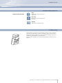
Symbols used in the Guide
Important safely instruction
Children safety
If this appliance is replacing an existing appliance which must be
removed or disposed of, make sure that it does not become a
dangerous trap for children by cutting its power supply cable and
rendering it impossible to close the door.
Use the same caution at the end of the lifespan of the new ap-
pliance.
Note
Tips for the correct use of the
appliance
Warning
directions to prevent injury
Important
Directions to avoid appliance
damage

4
www.fhiaba.com · [email protected] · Tel +39 (0)434 420160 · Fax +39 (0)434 420161
Appliance features and installation requirements
599 Series w: 599 mm (23 5/8”)/ h: 2050 mm (80 3/4”)/ d: 610 mm (24”)
749 Series w: 749 mm (29 1/2”)/ h: 2050 mm (80 3/4”)/ d: 610 mm (24”)
899 Series w: 899 mm (35 3/8”)/ h: 2050 mm (80 3/4”)/ d: 610 mm (24”)
599 Series w: 599 mm (23 5/8”)/ h: 2050 mm (80 3/4”))/ d: 635 mm (25”)
749 Series w: 749 mm (29 1/2”)/ h: 2050 mm (80 3/4”))/ d: 635 mm (25”)
899 Series w: 899 mm (35 3/8”)/ h: 2050 mm (80 3/4”))/ d: 635 mm (25”)
599 Series w: 599 mm (23 5/8”)/ h: 2120 mm (83 1/2”)/ d: 629 mm (24 3/4”)
749 Series w: 749 mm (29 1/2”)/ h: 2120 mm (83 1/2”)/ d: 629 mm (24 3/4”)
899 Series w: 899 mm (35 3/8”)/ h: 2120 mm (83 1/2”)/ d: 629 mm (24 3/4”)
599 Series w: 599 mm (23 5/8”)/ h: 2120 mm (84”)/ d: 635 mm (25”)
749 Series w: 749 mm (29 1/2”)/ h: 2120 mm (84”)/ d: 635 mm (25”)
899 Series w: 899 mm (35 3/8”)/ h: 2120 mm (84”)/ d: 635 mm (25”)
599 Series w: 650 mm (25 5/8”) / h: 2210 mm (87”)/ d: 800 mm (31 1/2”)
749 Series w: 800 mm (31 1/2”)/ h: 2210 mm (87”)/ d: 800 mm (31 1/2”)
899 Series w: 950 mm (37 3/8”) / h: 2210 mm (87”)/ d: 800 mm (31 1/2”)
599 Series w: 650 mm (25 5/8”) / h: 2260 mm (89”) / d: 800 mm (31 1/2”)
749 Series w: 800 mm (31 1/2”) / h: 2260 mm (89”) / d: 800 mm (31 1/2”)
899 Series w: 950 mm (37 3/8”) / h: 2260 mm (89”) / d: 800 mm (31 1/2”)
599 Series up to 230 kg (507 lb)
749 Series up to 275 kg (606 lb)
899 Series up to 295 kg (650 lb)
Europe Version: AC 220-240V 50 Hz / North America Version: 110V 60Hz
Europe Version: Schuko 16 A plug / North America Version: 15 A
from 0.05 MPa to 0.5 MPa (0.5 Bar - 5 Bar)
3/4” female attachment
Customized panels mounting Kit
Anti-tipping Kit (B04000200)
Lateral connecting kit (KCLIT/KCLIH)
4 mm (1/8”) allen wrench
Phillips head screwdriver
wood and percussion drill
2.5 mm (1/8”) bit for wood
8 mm (3/8”) bit for walls
17 mm (3/4”) wrench
Appliance dimensions
Integrated
Appliance dimensions
Classic
Appliance dimensions
StandPlus
Appliance dimensions
X-Pro
Appliance dimensions
Integrated / Classic
Appliance dimensions
StandPlus / X-Pro
Weight with packaging
Voltage
Power supply cable
Potable water supply pressure
Water supply tube
Provided installation accessories
Additional equipment necessary

5
min 2064 (81 ¼”)
A A
E W E W
140 (5 ½”) 140 (5 ½”)
100 (4”)
100 (4”)
S899: 900 (35 ½”)
S599: 600 (23 ¾”)
S749: 750 (29 ⁄”)
A
E
W
2064 mm (81 1/4”)
S899: 900 mm (35 1/2”)
S749: 750 mm (29 5/8”)
S599: 600 mm (23 3/4”)
S899: 1470 mm (57 7/8”)
S749: 1320 mm (52”)
S599: 1170 mm (46”)
105°
S899: 899 mm (35 3/8”)
S749: 749 mm (29 1/2”)
S599: 599 mm (23 5/8”)
2050 mm (80 3/4”)
+ 25 mm (1”)
610 mm (24”)
992 (39”)
S899: 1470 (57 ⁄”)
S749: 1320 (52”)
S599: 1170 (46”)
S899: 79 (3 ⁄”)
S749: 53 (2 ⁄”)
S599: 27 (1 ⁄”)
560 (22”)
610 (24”)
S899: 899 (35 ⁄”)
S749: 749 (29 ½”)
S599: 599 (23 ⁄”)
10 (⁄”)
105°
610 (24”)
560 (22”)
610 (24”)
560 (22”)
1293 (50 ⁄” )
474 (18 ⁄”)
231 (9
⁄”
) +
25 (1”)
500 (19 ¾”) 500 (19 ¾”)
248 (9
¾”
)
+ 25 (1”)
231 (9
⁄”
) +
25 (1”)
248 (9
¾”
)
+ 25 (1”)
20 (¾”)
15 (⁄”)
15 (⁄”)
20 (¾”)10 (⁄”)
721 (28 ⁄”) +25 (1”)
2050 (80 ¾”) +25 (1”)
2050 (80 ¾”) +25 (1”)
846 (33 ¼”) +25 (1”)
1168(46”)
330 (13”)
259 (10
¼”
)
1T/0T 0H
www.fhiaba.com · [email protected] · Tel +39 (0)434 420160 · Fax +39 (0)434 420161
Installation Guide
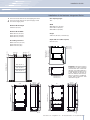
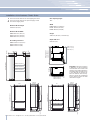
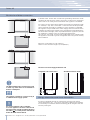
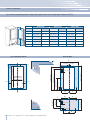
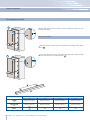
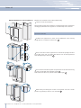
Installation niche features: Integrated Series
area to be left clear for the anti-tipping brackets
area to be left clear for the power supply cable
and water supply hose
Minimum Niche Height
Minimum Niche Width
Door Swing Clearance
Door Opening Angle
Width
Height
Depth with door (without panel)
Important: A 90° door opening
is sufÀ cient to allow opening
and full extraction of the inner
drawers, even if the appliance
is installed directly adjacent to
a wall. Should an opening at
105° be desired, then the ap-
pliance should be positioned
at the distance from the wall
described in À gure.

6
min 2064 (81 ¼”)
A A
E W E W
140 (5 ½”) 140 (5 ½”)
100 (4”)
100 (4”)
KS899: 900 (35 ½”)
KS599: 600 (23 ¾”)
KS749: 750 (29 ⁄”)
A
E
W
2064 mm (81 1/4”)
KS899: 900 mm (35 1/2”)
KS749: 750 mm (29 5/8”)
KS599: 600 mm (23 3/4”)
KS899: 1470 mm (57 7/8”)
KS749: 1320 mm (52”)
KS599: 1170 mm (46”)
105°
KS899: 899 mm (35 3/8”)
KS749: 749 mm (29 1/2”)
KS599: 599 mm (23 5/8”)
2050 mm (80 3/4”)
+ 25 mm (1”)
635 mm (25”)
KS899: 1470 (57 ⁄”)
KS749: 1320 (52”)
KS599: 1170 (46”)
560 (22”)
635 (25”)
KS899: 899 (35 ⁄”)
KS749: 749 (29 ½”)
KS599: 599 (23 ⁄”)
10 (⁄”)
105°
75 (3”)
58 (2 ¼”)
KS899: 138 (5 ½”)
KS749: 112 (4 ⁄”)
KS599: 86 (3 ⁄”)
635 (25”)
560 (22”)
1T/0T 0H
693 (27 ¼”)
635 (25”)
560 (22”)
693 (27 ¼”)
2050 (80 ¾”) +25 (1”)
1308 (51 ½”)587 (23 ⁄”)146 (5 ¾”) + 25(1”)
146 (5 ¾”) + 25(1”)
9 ( ⁄”)
732 (28 ⁄”)+25 (1”)
2050 (80 ¾”) +25 (1”)
857 (33 ¾”) +25 (1”)
1185 (46 ⁄”)
342 (13 ½”)362 (14 ¼”)
9 ( ⁄”)
6 ( ¼”)
www.fhiaba.com · [email protected] · Tel +39 (0)434 420160 · Fax +39 (0)434 420161
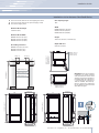
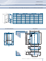
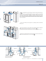
Installation niche features: Classic Series
area to be left clear for the anti-tipping brackets
area to be left clear for the power supply cable
and water supply hose
Minimum Niche Height
Minimum Niche Width
Door Swing Clearance
Door Opening Angle
Width
Height
Depth with door
Important: A 90° door opening
is sufÀ cient to allow opening
and full extraction of the inner
drawers, even if the appliance
is installed directly adjacent to
a wall. Should an opening at
105° be desired, then the ap-
pliance should be positioned
at the distance from the wall
described in À gure.

7
A A
min 2134 (84”)
MS899: 900 (35 ½”)
MS599: 600 (23 ¾”)
MS749: 750 (29 ⁄”)
140 (5 ½”) 140 (5 ½”)
100 (4”)
100 (4”)
E W E W
min 10 (⁄”)
A
E
W
2134 mm (84”)
MS899: 900 mm (35 1/2”)
MS749: 750 mm (29 5/8”)
MS599: 600 mm (23 3/4”)
MS899: 1470 mm (57 7/8”)
MS749: 1320 mm (52”)
MS599: 1170 mm (46”)
105°
MS899: 899 mm (35 3/8”)
MS749: 749 mm (29 1/2”)
MS599: 599 mm (23 5/8”)
2120 mm (83 1/2”)
+ 25 mm (1”)
629 mm (24 3/4”)
1010 (39 ¾”)
MS899: 120 (4 ¾”)
MS749: 94 (3 ¾”)
MS599: 68 (2 ⁄”)
560 (22”)
MS899: 899 (35 ⁄”)
MS749: 749 (29 ½”)
MS599: 599 (23 ⁄”)
10 (⁄”)
105°
629 (24 ¾”)
37 (1 ½”)
69 (2 ¾”)
MS899: 1470 (57
⁄”)
MS749: 1320 (52”)
MS599: 1170 (46”)
560 (22”)
2120 (83 ½”) +25 (1”)
613 (24 ⁄”)+25 (1”)
629 (24 ¾”)
615 (24 ¼”)
629 (24 ¾”)
615 (24 ¼”)
1T/0T
2120 (83 ½”) +25 (1”)
0H
128 (5) + 25 (1”)
666 (26 ¼”)
485 (19 ⁄”)
1296 (50”)
195 (7 ⁄”)
8 (⁄”)
8 (⁄”)
128 (5) + 25 (1”)
195 (7 ⁄”)
8 (⁄”)
8 (⁄”)
560 (22”)
666 (26 ¼”)
1170 (46”)
343 (13 ½”)
262 (10 ¼”)
6 ( ¼”)
749 (29 ½”) + 25 (1”)
www.fhiaba.com · [email protected] · Tel +39 (0)434 420160 · Fax +39 (0)434 420161
Installation Guide
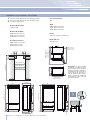
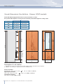
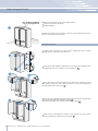
area to be left clear for the anti-tipping brackets
area to be left clear for the power supply cable
and water supply hose
Minimum Niche Height
Minimum Niche Width
Door Swing Clearance
Door Opening Angle
Width
Height
Depth with door
Installation niche features: StanPlus60 Series
Important: A 90° door opening
is sufÀ cient to allow opening
and full extraction of the inner
drawers, even if the appliance
is installed directly adjacent to
a wall. Should an opening at
105° be desired, then the ap-
pliance should be positioned
at the distance from the wall
described in À gure.

8
min 10 (⁄”)
A A
min 2134 (84”)
140 (5 ½”) 140 (5 ½”)
100 (4”)
100 (4”)
E W E W
XS899: 900 (35 ½”)
XS599: 600 (23 ¾”)
XS749: 750 (29 ⁄”)
A
E
W
2134 mm (84”)
XS899: 900 mm (35 1/2”)
XS749: 750 mm (29 5/8”)
XS599: 600 mm (23 3/4”)
XS899: 1470 mm (57 7/8”)
XS749: 1320 mm (52”)
XS599: 1170 mm (46”)
105°
XS899: 899 mm (35 3/8”)
XS749: 749 mm (29 1/2”)
XS599: 599 mm (23 5/8”)
2120 mm (83 1/2”)
+ 25 mm (1”)
635 mm (25 ”)
1016 (40”)
XS899: 1470 (57 ⁄”)
XS749: 1320 (52”)
XS599: 1170 (46”)
XS899: 138 (5 ½”)
XS749: 112 (4 ⁄”)
XS599: 86 (3 ⁄”)
560 (22”)
75 (3”)
XS899: 899 (35 ⁄”)
XS749: 749 (29”)
XS599: 599 (23 ⁄”)
10 (⁄”)58 (2 ¼”)
105°
635 (25”)
560 (22”)
2120 (83 ½”) +25 (1”)
613 (24 ⁄”)+25 (1”)
2120 (83 ½”) +25 (1”)
635 (25”)
128 (5) + 25 (1”)
693 (27 ¼”)
485 (19 ⁄”)
1296 (50”)
195 (7 ⁄”)
8 (⁄”)
8 (⁄”)
128 (5) + 25 (1”)
195 (7 ⁄”)
8 (⁄”)
8 (⁄”)
749 (29 ½”) + 25 (1”)
1170 (46”)
343 (13 ½”)262 (10 ¼”)
6 ( ¼”)
1T/0T 0H
www.fhiaba.com · [email protected] · Tel +39 (0)434 420160 · Fax +39 (0)434 420161
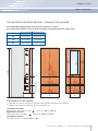
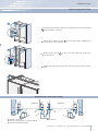
area to be left clear for the anti-tipping brackets
area to be left clear for the power supply cable
and water supply hose
Minimum Niche Height
Minimum Niche Width
Door Swing Clearance
Door Opening Angle
Width
Height
Depth with door
Installation niche features: X-Pro Series
Important: A 90° door opening
is sufÀ cient to allow opening
and full extraction of the inner
drawers, even if the appliance
is installed directly adjacent to
a wall. Should an opening at
105° be desired, then the ap-
pliance should be positioned
at the distance from the wall
described in À gure.

9
1
4
1
2
3
www.fhiaba.com · [email protected] · Tel +39 (0)434 420160 · Fax +39 (0)434 420161
Installation Guide
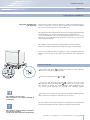
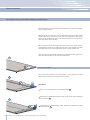
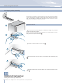
The appliance is very heavy.
Take maximum care during handling to
avoid injury.
The appliance should always be transport-
ed in an erect position.
Avoid at all costs leaning it on its front side.
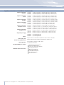
Preparing the installation
Transport to installation site
and unpacking
Since this is a large and heavy appliance, before transporting the ap-
pliance, check the access to the location where it will be installed
(door size, manoeuvring space in stairwells, etc.).
The appliance is attached to the base of the packaging (pallet) through
four bolts which can be removed using a 17 mm (3/4”) wrench.
It is recommended to use a manual transporting device to move the
appliance to the installation site, and only at this point to remove the
base of the packaging.
The appliance should always be transported in an erect position.
If this is not possible, transport the appliance laying on its rear side.
Once at the installation site, the appliance, which is equipped with four
wheels, can be taken off the pallet and positioned in the installation
area.
Operate as follows:
Take off the four bolts
1
securing the appliance to the pallet by
means of a 17 mm (3/4”) open spanner.
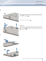
Remove the À xing brackets
3
and
4
.
To remove the front À xing bracket
3
, unscrew for one or two
turns the rear wheel adjusting bolt
2
by means of a 13 mm (1/2”)
box spanner, avoiding too much strenght while thightening the
nut, which could damage the leveling feet adjusting system.
From the back of the unit and by means of a suitable, high duty hand
trolley, take off the appliance and place it on the Á oor.
Be very careful to avoid any damage to Á oors. Delicate Á oors should be
protected with plywood, hard cardboard or similar material panels.
Series: All

EW
E W
EW
E W
10
E
W
E
W
www.fhiaba.com · [email protected] · Tel +39 (0)434 420160 · Fax +39 (0)434 420161
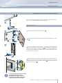
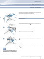
Electrical and Water connection
A Schuko 16 A socket with an efÀ cient grounding should be made
available for the electrical mains connection, as well as an omnipolar
switch which can easily be reached when the appliance is installed.
To connect to the water supply system (for appliances equipped with
ice makers) a tap with a male 3/4” connection should be provided,
which must also be easily accessible once the appliance is installed.
The appliance is provided with a water supply hose and seal kit which
is suitable for high water pressure and complies the Food Regulations.
The water À lter cartridge, which is provided with the appliance, should
be installed according to the accompanying instructions.
Use only the new hose and the new gaskets which are supplied with
the appliance. Discard any hose and gasket which may have already
been installed.
Electrical cord length: 2,0 mt (78 3/4”)
Water connection line length: 2,5 mt (98 3/8”)
Series: All
Do not use extension cords or adapters.
Once the appliance has been connected to
the water system, turn the Ice Maker off (touch
the button
on control panel to switch it off)
before the main water is shut off.
The appliance should be connected only to
a drinkable water supply system.
The Built-in Fhiaba À lter cannot make it safe
to drink any water which is not suitable for
human consumption.
Energy: Alternatives and Home Automation
If energy is supplied through an alternative energy power source
(solar, geothermal, etc..) or if home automation systems are installed,
it is necessary to install the Alternative Energy Kit to integrate the unit
into the power grid.
Electrical and water supply behind the unit
Integrated and Classic Series StandPlus and X-Pro Series

2
1
11
www.fhiaba.com · [email protected] · Tel +39 (0)434 420160 · Fax +39 (0)434 420161
Installation Guide
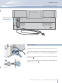
Back of appliance
Water connection
Electrical connection
Series: Integrated/Classic
Operate as follows:
Unwind the electric cable and connect it directly to the wall socket.
Make sure the appliance is in the Stand-by condition and that all
lights are off; should it be not so press the Unit button to switch it
off.
Fit one end of the water hose onto the connector at the appli-
ance’s back
1
.
Fit the other end of the hose to the water tap, use the gaskets pro-
vided in the Owner’s Kit
2
.

2
1
12
www.fhiaba.com · [email protected] · Tel +39 (0)434 420160 · Fax +39 (0)434 420161
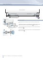
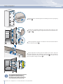
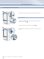
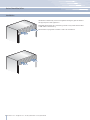
Series: StandPlus/X-Pro
Operate as follows:
Unwind the electric cable and connect it directly to the wall socket.
Make sure the appliance is in the Stand-by condition and that all ights
are off; should it be not so press the Unit button to switch it off.
Connect the water line to the threaded connection at the base of the
unit, as in À gure
1
.
Fit the other end of the hose to the water tap, use the gaskets provided
in the Owner’s Kit
2
.
Back of appliance
Front of appliance
Water connectionElectrical connection

13
1
2
1
2
www.fhiaba.com · [email protected] · Tel +39 (0)434 420160 · Fax +39 (0)434 420161
Installation Guide
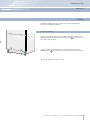
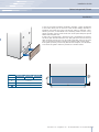
Adjust the appliance level by means of the front levelling feet
and the rear adjustable wheels.
Operate as follows:
After removing the bottom plinth or grille (it is kept in position by
magnets), adjust the height of the levelling feet
1
by means of a 17
mm (3/4”) open spanner.
Then adjust the height of the rear wheels by turning the front
adjusting bolts
2
clockwise or anticlockwise as it may be required.
Remount the bottom plinth or grille.
Levelling
Series: All

14
1
2
3
www.fhiaba.com · [email protected] · Tel +39 (0)434 420160 · Fax +39 (0)434 420161
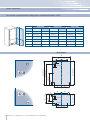
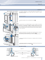
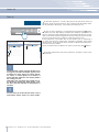
Decorative door and bottom-drawer panels layout
The dimensions of the panels are indicated in the table and draw-
ings on pages 18-21.
Nevertheless, according to the requirements for aligning with other
kitchen structures, the door panel can be higher than the upper
edge of the refrigerator door, and the drawer panel can be lower
than the edge of the drawer.
The panels must be mounted using special braces which attach
to adjustable devices provided on the door and drawer and with
brackets that anchor and adjust the panel’s vertical direction.
Braces, brackets and fixing screws are provided with the appliance
and must be applied to the panel as indicated.
Operate as follows:
To prepare the panels to be mounted on the appliance, follow
these steps, working on the back of the panel.
Door Panel
Trace, a line dividing the panel width in half
1
.
Starting form the Bottom edge of the panel, mark the positioning
of the brackets
2
.
Following the corresponding table, mark the external and then
the internal hole
3
.
Series: Integrated

15
7
8
4
5
www.fhiaba.com · [email protected] · Tel +39 (0)434 420160 · Fax +39 (0)434 420161
Installation Guide
Position the brackets on each set of marks to make sure they are
aligned
4
, then drill holes through the panel (pay close attention
to the panel’s thickness)
5
.
Screw the brackets in place
6
.
Drawer Panel
When preparing the Drawer Panel, follow the same instructions as
per the door panel, but make sure measurements are taken starting
from the top edge
7
. The support bracket faces the opposite way
8
(note imgs 4 and 8).
Series: Integrated

16
D E
D E
A
B C
F G
13 (½”)
13 (
½”)
34 (1
⁄”)
34 (1
⁄”)
1285 (50 ⁄”)
1163 (45
¾”)
660 (26”)
157 (6
¼”)
min 1320 (52”)max 635 (25”)
507,5 (20”)
382 (15
⁄”)
100 (4”)
A
897 (35 ¼”) 897 (35
¼”) 747 (29 ⁄”) 747 (29 ⁄”) 597 (23 ½”)
355.5 (14”)
355.5 (14”)
279 (11”)
279 (11”)
205 (8
⁄”)
205 (8
⁄”)261 (10 ¼”)
261 (10 ¼”)
187 (7 ⁄”)
187 (7
⁄”)
111 (4
⁄”)
111 (4
⁄”)
418 (16
½”)
418 (16
½”)
343 (13
½”)
343 (13
½”)
276.5 (10 ⁄”)
276.5 (10 ⁄”)386 (15 ¼”)
386 (15
¼”)
311 (12
¼”)
311 (12
¼”)
236.5 (9
⁄”)
236.5 (9 ⁄”)
B
C
D
E
354.5 (14”) 354.5 (14”) 279.5 (11”) 279.5 (11”) 203.5(8”)
597 (23
½”)
203.5(8”)
F / G
www.fhiaba.com · [email protected] · Tel +39 (0)434 420160 · Fax +39 (0)434 420161
Decorative panels layout for Fridge with one Bottom-Drawer (1T/0T)
Series 899
Hinge Left Hinge Left Hinge Left
Hinge Right Hinge Right Hinge Right
Series 749
Series 599
Holes positions
Series: Integrated

17
D E
A
B
C
F G
D E
13 (½”)
13 (
½”)
34 (1
⁄”)
min 1195 (47”)
1160 (45
⁄”)
1044 (41
⁄”)
600 (23
⁄”)
268 (10
½”)
292,5 (11
½”)
183 (7
¼”)
73 (2
⁄”)
66 (2
⁄”) 157 (6 ¼”)
337 (13
¼”)
max 415 (16
⁄”)
A
897 (35 ¼”) 897 (35
¼”) 747 (29 ⁄”) 747 (29 ⁄”) 597 (23 ½”)
355.5 (14”)
355.5 (14”)
279 (11”)
279 (11”)
205 (8
⁄”)
205 (8
⁄”)261 (10 ¼”)
261 (10 ¼”)
187 (7 ⁄”)
187 (7
⁄”)
111 (4
⁄”)
111 (4
⁄”)
418 (16
½”)
418 (16
½”)
343 (13
½”)
343 (13
½”)
276.5 (10 ⁄”)
276.5 (10 ⁄”)386 (15 ¼”)
386 (15
¼”)
311 (12
¼”)
311 (12
¼”)
236.5 (9
⁄”)
236.5 (9 ⁄”)
B
C
D
E
354.5 (14”) 354.5 (14”) 279.5 (11”) 279.5 (11”) 203.5(8”)
597 (23
½”)
203.5(8”)
F / G
www.fhiaba.com · [email protected] · Tel +39 (0)434 420160 · Fax +39 (0)434 420161
Installation Guide
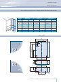
Decorative panels layout for Fridge with two Bottom-Drawers (0H)
Holes positions
Series 899
Hinge Left Hinge Left Hinge Left
Hinge Right Hinge Right Hinge Right
Series 749
Series 599
Series: Integrated

18
H I
D E
A
F G
1286 (50 ⁄”)
6,5 (¼”)
6,5 (
¼”)
1152,5 (45 ⁄”)
650,5 (13
⁄”)
148,5 (5
⁄”)
13 (½”)
34 (1
⁄”)
34 (1 ⁄”)
min 1320 (52”)
max 635 (25”)
507,5 (20”)
382 (15
⁄”)
100 (4”)
899: 627 (24 ⁄”)
749: 477 (18
¾”)
599: 327 (12
⁄”)
1075 (42 ⁄”)
min 130 (5 ⁄”)
115 (4
½”)
135 (5
⁄”)
135 (5
⁄”)
A
H
I
F / G
897 (35 ¼”) 897 (35 ¼”)
747 (29 ⁄”) 747 (29 ⁄”) 597 (23 ½”) 597 (23 ½”)
354.5 (14”) 354.5 (14”) 279.5 (11”) 279.5 (11”) 203,5(8”) 203,5(8”)
412 (16
¼”)
412 (16
¼”)
337 (13
¼”)
337 (13
¼”)
270.5 (10 ⁄”)
270.5 (10
⁄”)380 (15”)
380 (15”)
305 (12”)
305 (12”)
230.5 (9
⁄”)
230.5 (9 ⁄”)
418 (16
½”)
418 (16
½”)
343 (13
½”)
343 (13
½”)
276.5 (10
⁄”)
276.5 (10 ⁄”)386 (15 ¼”)
386 (15
¼”)
311 (12
¼”)
311 (12
¼”)
236.5 (9
⁄”)
236.5 (9
⁄”)
D
E
www.fhiaba.com · [email protected] · Tel +39 (0)434 420160 · Fax +39 (0)434 420161
Decorative panels layout for Fridge with glass door and one Bottom-Drawer (1T/0T)
Holes positionsDoor window dimensions
Series: Integrated
Series 899
Hinge Left Hinge Left Hinge Left
Hinge Right Hinge Right Hinge Right
Series 749
Series 599
La page est en cours de chargement...
La page est en cours de chargement...
La page est en cours de chargement...
La page est en cours de chargement...
La page est en cours de chargement...
La page est en cours de chargement...
La page est en cours de chargement...
La page est en cours de chargement...
La page est en cours de chargement...
La page est en cours de chargement...
La page est en cours de chargement...
La page est en cours de chargement...
La page est en cours de chargement...
La page est en cours de chargement...
La page est en cours de chargement...
La page est en cours de chargement...
La page est en cours de chargement...
La page est en cours de chargement...
La page est en cours de chargement...
La page est en cours de chargement...
-
 1
1
-
 2
2
-
 3
3
-
 4
4
-
 5
5
-
 6
6
-
 7
7
-
 8
8
-
 9
9
-
 10
10
-
 11
11
-
 12
12
-
 13
13
-
 14
14
-
 15
15
-
 16
16
-
 17
17
-
 18
18
-
 19
19
-
 20
20
-
 21
21
-
 22
22
-
 23
23
-
 24
24
-
 25
25
-
 26
26
-
 27
27
-
 28
28
-
 29
29
-
 30
30
-
 31
31
-
 32
32
-
 33
33
-
 34
34
-
 35
35
-
 36
36
-
 37
37
-
 38
38
-
 39
39
-
 40
40


dans d''autres langues
- English: Fhiaba BKI36BI-LS Installation guide
Documents connexes
Autres documents
-
Bertazzoni REF30BMBIXLT 15.5 cu. ft. Built-in Bottom Freezer Refrigerator Guide d'installation
-
Signature Kitchen Suite SKSCW241RP Guide d'installation
-
Bertazzoni REF36PIXL Le manuel du propriétaire
-
Bertazzoni REF24FCIPIXR Guide d'installation
-
-
Bertazzoni 30 Inch Built In Bottom Freezer Refrigerator Manuel utilisateur
-
Bertazzoni REF30PIXL DL 0cc4a7a38ffeb385cb6a68f8cae1
-
LAMONA LAM6401 Le manuel du propriétaire