Samsung CHW9150GW Le manuel du propriétaire
- Catégorie
- Machines à laver
- Taper
- Le manuel du propriétaire
Ce manuel convient également à

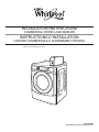
INSTALLATION INSTRUCTIONS
COMMERCIAL FRONT-LOAD WASHER
INSTRUCTIONS D’INSTALLATION
LAVEUSE COMMERCIALE À CHARGEMENT FRONTAL
Table of Contents/Table des matières . . . . . . . . . . . . . . . . . . . . . . . . . . . . . . . . . . . . . . . . 2
W10726004B
www.whirlpoolcommerciallaundry.com

2
TABLE OF CONTENTS
WASHER SAFETY ................................................................................... 3
INSTALLATION REQUIREMENTS ..........................................................4
Tools and Parts .....................................................................................4
Accessories .......................................................................................... 4
Options .................................................................................................4
Location Requirements ........................................................................5
Drain System ........................................................................................ 5
Electrical Requirements........................................................................6
INSTALLATION INSTRUCTIONS ............................................................6
Remove Transport System ................................................................... 6
Connect the Inlet Hoses .......................................................................7
Connect the Drain Hose ....................................................................... 8
Secure the Drain Hose .........................................................................8
Level the Washer .................................................................................. 9
Complete Installation............................................................................9
USER & SET-UP INSTRUCTIONS ........................................................ 10
General User Information ...................................................................10
Control Set-up Procedures ................................................................10
Start Operating Set-up ....................................................................... 11
WASHER CARE .....................................................................................13
Cleaning Your Washer ........................................................................ 13
Water Inlet Hoses ............................................................................... 13
ASSISTANCE OR SERVICE .................................................................. 13
WARRANTY ........................................................................................... 14
TABLE DES MATIÈRES
SÉCURITÉ DE LA LAVEUSE ................................................................15
EXIGENCES D’INSTALLATION ............................................................16
Outillage et pièces ..............................................................................16
Accessoires ........................................................................................16
Options ...............................................................................................17
Exigences d’emplacement ................................................................. 17
Système de vidange ...........................................................................18
Spécifications électriques ..................................................................18
INSTRUCTIONS D’INSTALLATION ...................................................... 19
Dépose du système de transport ....................................................... 19
Raccordement des tuyaux d’alimentation..........................................20
Raccordement du tuyau de vidange ..................................................21
Immobilisation du tuyau de vidange ..................................................21
Réglage de l’aplomb de la laveuse ....................................................22
Achever l’installation ..........................................................................22
INSTRUCTIONS D’UTILISATION ET D’INSTALLATION .....................23
Informations générales ....................................................................... 23
Procédures de réglage des systèmes de commande ........................ 23
Paramétrage pour mise en marche .................................................... 24
ENTRETIEN DE LA LAVEUSE ..............................................................26
Nettoyage de la laveuse .................................................................... 26
Tuyaux d’arrivée d’eau .......................................................................27
ASSISTANCE OU SERVICE .................................................................. 27
GARANTIE ............................................................................................. 27

3
WASHER SAFETY

4
Alternate Parts
Your installation may require additional parts. If you are interested
in purchasing one of the items listed here, call the toll-free number
in the “Assistance or Service” section.
If you have You will need to buy
Laundry tub or standpipe
taller than 96" (2.4 m)
Sump pump system (if not already
available)
Overhead sewer Standard 20 gal. (76 L), 30"
(762 mm) tall drain tub or utility sink
and sump pump (available from
local plumbing suppliers)
Floor drain Siphon break, Part Number 285834;
additional drain hose,
Part Number 8318155; and
connector kit, Part Number 285835
Drain hose too short 4 ft (1.2 m) drain hose extension kit,
Part Number 285863
Water faucets beyond
reach of fill hoses
2 longer water fill hoses:
6 ft (1.8 m) Part Number 76314
10 ft (3.0 m) Part Number 350008
Accessories
Enhance your washer with these premium accessories.
For more high-quality items or to order, call 1-800-901-2042,
or visit us at www.whirlpool.com/accessories. In Canada call:
1-800-807-6777 or visit us at www.whirlpoolparts.ca.
Part Number Accessory
8212526
Washer drip trays, fits under all
31682
All purpose appliance cleaner
1903WH
Laundry supply storage cart
Options
Pedestal
You have the option of purchasing pedestals separately for this
washer. The pedestal will add to the total height of the washer.
Optional pedestal
Pedestal
Height
Approximate
height with washer
Color
Part Number
2
7
⁄8" (73 mm) *47.5" (1207 mm) White WHP0400VW
*Add
5
⁄8" (16 mm) minimum for leveling feet.
INSTALLATION REQUIREMENTS
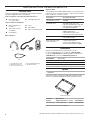
Tools and Parts
Gather the required tools and parts before starting installation.
The parts supplied are in the washer drum.
Tools needed for connecting the water inlet hoses:
■ Pliers (that open to
1
9
⁄16" [39.5 mm])
■ Flashlight (optional)
Tools needed for installation:
■ Open end wrenches
½" and
9
⁄16"
■ Torx T-20
®†
Security
screwdriver
■ ¼" Nut driver
■ Level
■ Wood block
■ Ruler or measuring tape
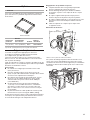
A. U-shaped hose form
B. Water inlet hoses (2)
C. Inlet hose washers (4)
D. Transit bolt hole plug (4)
E. Beaded tie strap
A B
C
E
D
Parts supplied:
®† TORX and T20 are registered trademarks of Acument Intellectual Properties, LLC.

5
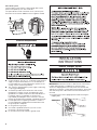
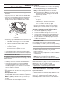
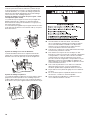
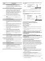
Door is not reversible
28
13
/16"
(732 mm)
44
5
/8"
(1134 mm)
27"
(686 mm)
50 ½"
(1282 mm)
Washer Dimensions
A floor drain should be provided under the bulkhead. Prefabricated
bulkheads with electrical outlets, water inlet lines, and drain facilities
should be used only where local codes permit.
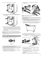
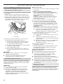
Drain System
The washer can be installed using the standpipe drain system
(floor or wall), the laundry tub drain system, or the floor drain
system. Select the drain hose installation method you need.
See “Tools and Parts.”
Standpipe drain system – wall or floor (views A & B)
The standpipe drain requires a minimum diameter standpipe
of 2" (50 mm). The minimum carry-away capacity can be no less
than 12 gal. (45.5 L) per minute, per washer.
The top of the standpipe must be at least 30" (762 mm) high
and no higher than 96" (2.4 m) from the bottom of the washer.
30" min.
(762 mm)
A B
Laundry tub drain system
The laundry tub needs a minimum 20 gal. (76 L) capacity. The top
of the laundry tub must be at least 30" (762 mm) above the floor.
Location Requirements
Selecting the proper location for your washer improves
performance and minimizes noise and possible washer “walk.”
Your washer can be installed under a custom counter, or in a
basement, laundry room, or recessed area. See “Drain System.”
Companion appliance location requirements should also be
considered. Proper installation is your responsibility.
You will need:
■ A water heater set to deliver 120°F (49°C) water to the washer.
■ A grounded electrical outlet located within 6 ft. (1.8 m) of
where the power cord is attached to the back of the washer.
See “Electrical Requirements.”
■ Hot and cold water taps located within 4 ft. (1.2 m) of the hot
and cold water fill valves, and water pressure of 20–100 psi
(137.9–689.6 kPa).
■ A level floor with a maximum slope of 1" (25 mm) under entire
washer. Installing the washer on soft floor surfaces, such as
carpets or surfaces with foam backing, is not recommended.
■ A sturdy and solid floor to support the washer with a total
weight (water and load) of 400 lbs (180 kg).
Do not operate your washer in temperatures below 32°F (0°C).
Some water can remain in the washer and can cause damage
in low temperatures.
Installation clearances
■ The location must be large enough to allow the washer door
to be fully opened.
■ Additional spacing should be considered for ease of
installation and servicing. The door opens more than 90°,
and it is not reversible.
■ Additional clearances might be required for wall, door,
and floor moldings.
■ Additional spacing of 1" (25 mm) on all sides of the washer
is recommended to reduce noise transfer.
■ Companion appliance spacing should also be considered.
30" min.
(762 mm)
*Height without leveling feet installed.
*

6
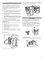
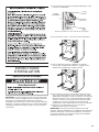
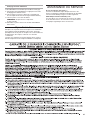
Shipping bolt with plastic spacer
INSTALLATION
INSTRUCTIONS
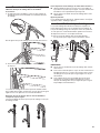
Remove Transport System
IMPORTANT: Position the washer so that the rear of the washer
is within approximately 3 ft. (900 mm) of its final location.
There are 4 shipping bolts in the rear panel of the washer that
support the suspension system during transportation. These bolts
also retain the power cord inside the washer until the bolts are
removed.
1. Keep the washer in the upright position while removing the
shipping bolts.
Shipping bolt
Shipping bolt
Back view
Floor drain system
The floor drain system requires a siphon break that may be
purchased separately. See “Tools and Parts.”
The siphon break must be a minimum of 28" (710 mm) from
the bottom of the washer. Additional hoses might be needed.
Electrical Requirements
■ A 120 volt, 60 Hz., AC only, 15- or 20-amp, fused electrical
supply is required. A time-delay fuse or circuit breaker is
recommended. It is recommended that a separate circuit
serving only this washer be provided.
■ This washer is equipped with a power supply cord having
a 3 prong grounding plug.
■ To minimize possible shock hazard, the cord must be
plugged into a mating, 3 prong, grounding-type outlet,
grounded in accordance with local codes and ordinances.
If a mating outlet is not available, it is the personal
responsibility and obligation of the customer to have the
properly grounded outlet installed by a qualified electrician.
■ If codes permit and a separate ground wire is used, it is
recommended that a qualified electrician determine that
the ground path is adequate.
■ Do not ground to a gas pipe.
■ Check with a qualified electrician if you are not sure
the washer is properly grounded.
■ Do not have a fuse in the neutral or ground circuit.
28" min.
(710 mm)

7
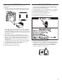
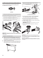
2. Using a ½" wrench, loosen each of the bolts.
3. Once the bolt is loose, move it to the center of the hole
and completely pull out the bolt, including the plastic spacer
covering the bolt.
4. Once all 4 bolts are removed, discard the bolts and spacers.
Then push the power cord plug into the opening on the right
side of the rear panel and pull the power cord through the
opening on the left side of the rear panel and close holes with
the attached cap. Do not pull plug end of power cord through
the right side hole.
5. Close the bolt holes with the 4 transport bolt hole plugs.
NOTE: If the washer is to be transported at a later date, call your
product distributor or installer. To avoid suspension and structural
damage, your washer must be properly set up for relocation
by a trained professional.
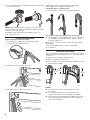
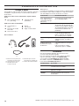
Connect the Inlet Hoses
Insert new flat washers (supplied) into each end of the inlet
hoses. Firmly seat the washers in the couplings.
A B
A. Coupling
B. Washer
Connect the inlet hoses to water faucets
Make sure the washer drum is empty.
1. Attach a hose to the hot water faucet. Screw on coupling
by hand until it is seated on the washer.
2. Attach a hose to the cold water faucet. Screw on coupling
by hand until it is seated on the washer.
3. Using pliers, tighten the couplings with an additional
two-thirds turn.
NOTE: Do not overtighten, use tape, or sealants on the valve.
Damage to the valves can result.
Clear water lines
■ Run water through both faucets and inlet hoses, into a
laundry tub, drainpipe, or bucket, to get rid of particles in the
water lines that might clog the inlet valve screens.
■ Check the temperature of the water to make sure that the hot
water hose is connected to the hot water faucet and that the
cold water hose is connected to the cold water faucet.
Connect the inlet hoses to the washer
C. Cold water inlet
H. Hot water inlet
1. Attach the hot water hose to the check valve on washer’s
hot (H) water inlet valve. Screw on coupling by hand until
it is seated on the check valve.
2. Attach the cold water hose to the check valve on washer’s
cold (C) water inlet valve. Screw on coupling by hand until
it is seated on the check valve.
3. Using pliers, tighten the couplings with an additional
two-thirds turn.
NOTE: Do not overtighten. Damage to the coupling can result.

8
4. Turn on the water faucets completely and check for leaks and
at washer connection.
NOTE: Replace inlet hoses after 5 years of use to reduce the
risk of hose failure. Record hose installation or replacement dates
on the hoses for future reference.
Periodically inspect and replace hoses if bulges, kinks, cuts,
wear, or leaks are found.
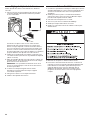
Connect the Drain Hose
Remove drain hose from washer drum
1. Use locking pliers, squeeze hose clamp tabs together
and insert over the end of drain hose.
2. Slide drain hose onto washer connection.
3. Once drain hose is in place, release pliers.
Washer drain system can be installed using a floor drain,
wall standpipe, floor standpipe, or laundry tub.
Laundry tub drain or standpipe drain
Connect the drain hose form to the corrugated drain hose.
To keep drain water from going back into the washer:
■ Use the drain hose form, and do not force excess drain hose
into standpipe. Hose should be secure, but loose enough
to provide a gap for air.
■ Do not lay excess hose on the bottom of the laundry tub.
Floor drain
You may need additional parts. See Floor drain under
“Tools and Parts.”
Secure the Drain Hose
Drain hose must be secured to stop the hose from moving when
water is pumped out. If the drain hose moves, water may end up
on the floor.
1. Drape the power cord over the washer top.
2. Move the washer to its final location.
3. Place the drain hose in the laundry tub or standpipe as shown.
See illustrations A and B.
A B C
NOTES:
■ Do not force excess drain hose back into the rear of
the washer.
■ To avoid siphoning, do not seal or put more than 4½"
(114 mm) of the drain hose into drainpipe or standpipe.
■ If the washer faucets and the drain standpipe are recessed,
put the hooked end of the drain hose in the standpipe as
shown. See illustration C.
114 mm
(4
1
/2")
114 mm
(4
1
/2")
114 mm
(4
1
/2")
4½"
(114 mm)
4½"
(114 mm)
4½"
(114 mm)

9
Level the Washer
Properly leveling your washer avoids excessive noise
and vibration.
1. Check the levelness of the washer by placing a level on the
top edge of the washer, first side to side, then front to back.
If the washer is against a wall, move the washer out slightly
before tipping back. If the washer is not level, first prop the
front with a wood block and adjust the feet as necessary; then
prop the back and adjust feet as necessary. Repeat this step
until washer is level.
2. Make sure all four feet are stable and resting on the floor.
Then check that the washer is perfectly level (use a level).
3. After the washer is level, use a 9/16" open-end wrench to turn
the nuts on the feet tightly against the washer cabinet.
IMPORTANT: All four feet must be tightened. If the nuts are
not tight against the washer cabinet, the washer may vibrate.
4. The washer should not move front to back, side to side,
or diagonally when pushed on its top edges.
5. Slide the washer to its final location.
6. Confirm the levelness of the washer.
Complete Installation
1. Check the electrical requirements. Be sure that you have the
correct electrical supply and the recommended grounding
method. See “Electrical Requirements.”
2. Check that all parts are now installed. If there is an extra part,
go back through the steps to see which step was skipped.
3. Check that you have all of your tools.
4. Dispose of/recycle all packaging materials.
5. Check that the water faucets are on.
6. Check for leaks around faucets and inlet hoses.
7. Plug into an grounded 3 prong outlet.
8. To test and to clean your washer, measure ½ the detergent
manufacturer’s recommended amount of High Efficiency (HE)
detergent for a medium-size load. Pour the detergent into
the detergent dispenser. Select any cycle and allow the
washer to complete one whole cycle.

10
NOTE: After the washer has been installed and plugged in, the
display may show ‘0 MINUTES’. Once the washer has been
plugged in and the washer door opened and closed, the display
will show the price. In washers set for free cycles, the display will
flash ‘SELECT CYCLE’.
1. Insert coins until ‘SELECT CYCLE’ flashes in display.
2. Door must be closed before cycle selection is made,
3. Press fabric setting button for the wash cycle desired. After
the cycle is started, the time will display and count down.
4. If a cycle is interrupted by opening the door, ‘RESELECT
CYCLE’ will flash in the display. To restart the washer, close
door, and reselect desired cycle.
General User Information
SCROLLING ‘OUT OF ORDER’ SHOWING IN DISPLAY
This condition indicates the washer is inoperative.
‘0 MINUTES’ SHOWING IN DISPLAY
This indicates the cycle is complete and the washer cannot be
operated. Coins dropped or debit inputs during this condition will
be stored in escrow but cannot be used until normal operation is
restored by opening and closing the door. If a door switch fails, it
must be replaced before normal operation can be restored.
COLD START (Initial first use)
Washer is programmed at the factory as follows:
11-minute wash period
3 rinses (extra rinse not enabled)
$2.00 wash price (9050 model)
$0 wash price (9060 model)
WARM START (after power failure)
A few seconds after power is restored, if a cycle was in progress at
the time of the power failure, ‘RESELECT CYCLE’ will flash in the
display, indicating the need for a key press to restart the washer.
DOOR LOCK
Prior to beginning a cycle, there is a door lock routine of lock/
unlock/relock; then cycle begins. The door will remain locked
until the end of a cycle or approximately 2 minutes after a
power interruption.
PRICING
After the door is opened following the completion of a cycle, the
display indicates the cycle price (unless set for free operation). As
coins are dropped or debit inputs arrive, the display will change to
lead the user through the initiation of a cycle.
FREE CYCLES
This is established by setting the cycle price to zero. When this
happens, ‘SELECT CYCLE’ will appear rather than a cycle price.
DEBIT CARD READY
This washer is debit card ‘cable’ ready. It will accept a variety of
debit card systems, but does NOT come with a debit card reader.
Refer to the debit card reader manufacturer for proper washer
set-up. In models converted to a Generation 1 debit card system,
debit pulses represent the equivalent of one coin (coin 1).
Control Set-up Procedures
IMPORTANT: Read all instructions before operating.
9050 Models: Insert access door key, turn, and lift to remove
access door.
9060 Models: Once the debit card reader is installed (according
to the reader manufacturer’s instructions), the set-up mode can
only be entered by inserting a set-up card (supplied by the reader
manufacturer) into the card slot. If a set-up card is not available,
diagnostic modes can be entered by removing connector AA1 on
the circuit board or by using the Service Access Code (see Service
Access Code section, page 12) for 9060 models.
IMPORTANT: Unplug washer or disconnect power before opening
the console. To access connector AA1:
1. Unplug washer or disconnect power.
2. Open console, disconnect plug on AA1, close console.
3. Plug in washer or reconnect power.
The washer is now in the set-up mode. The lower 3 buttons and
the digital display are used to set up the controls. The display
can contain 4 numbers and/or letters and a decimal point. These
are used to indicate the set-up codes and related code values
available for use in programming the washer.
Once the washer has been programmed with a Gen 2 card reader
installed, the washer will be in dAS mode permanently, and dAS
will be displayed every time set-up mode is accessed.
The lower fabric setting buttons and the digital display are used to
set up the controls.
The display can contain 4 numbers and/or letters and a decimal
point. These are used to indicate the set-up codes and related
code values available for use in programming the washer.
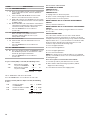
HOW TO USE THE BUTTONS TO PROGRAM THE CONTROLS
1. The HOT button is used to adjust the values associated with
set-up codes. Pressing the button will change the value by
increments. Rapid adjustment is possible by holding down
the button.
2. The WARM button will advance through the set-up codes.
Pressing the button will advance to the next available set-up
code. Holding the button down will automatically advance
through the set-up codes at a rate of 1 per second.
3. The COLD button is used to select or deselect options.
USER & SETUP INSTRUCTIONS

11
Start Operating Set-up
Before proceeding, it is worth noting that, despite all of the
options available, an owner can simply choose to uncrate a new
commercial washer, hook it up, plug it in, and have a washer
that operates.
Washers are preset at the factory for an 11-minute wash period
and 3 rinses (no extra rinse).
SET-UP CODES
■ The
WARM
button will advance you from code to code.
■ The
HOT
button will change the code value.
■ The
COLD
button will select or deselect options.
The set-up code is indicated by the one or two left-hand
characters. The set-up code value is indicated by the two
or three right-hand characters.
NOTE: The first line of each code indicates the factory default
for 9050 models.
CODE EXPLANATION
6 01
REGULAR CYCLE PRICE (Factory Default)
6 01 When the d.xx is set to d.CS, this 6 xx value
represents the number of push-in actuations of the
coin slide to start the washer. 6 01 would equal one
coin slide activation.
6
00
g
When the d.xx is set to d.00, this 6 xx value
represents the number of coins needed to start the
washer; may adjust from 0–39. Change this value
by pressing the HOT button. 6 07 = 7 coins. 9060
models default to 6 00.
Press the
WARM
button once to advance
to next code.
8 00
ADDITIONAL RINSE OPTION
This option is either SELECTED ‘ON’ or NOT
SELECTED ‘OFF’.
8
8
00
Ar
g
Not Selected ‘OFF’.
Selected ‘ON’.
Press the
COLD
button once for this selection.
Press the
WARM
button once to advance
to next code.
9 00
CYCLE COUNTER OPTION
This option is either SELECTED ‘ON’ or NOT
SELECTED ‘OFF’.
9
9
00
0C
g
Not Selected ‘OFF’.
Selected ‘ON’ and not able to be deselected.
Press the
COLD
button 3 consecutive times to select
‘ON’. Once selected ‘ON’ it cannot be deselected.
Press the
WARM
button once to advance
to next code.
CODE EXPLANATION
1. 00
MONEY COUNTER OPTION
This option is either SELECTED ‘ON’ or NOT
SELECTED ‘OFF’.
1.
1.
1
00
0C
C0
g
Not Selected ‘OFF’.
Selected ‘ON’.
Press the
COLD
button 3 consecutive times to
select ‘ON’ and 3 consecutive times to remove
(Not Selected ‘OFF’.) Counter resets by going
from ‘OFF’ to ‘ON’.
Selected ‘ON’ and not able to be deselected.
To select ‘ON’ and not able to be deselected,
first select ‘ON’, then within 2 seconds, press
the
COLD
twice,
HOT
once, and exit the set-up
mode.
Press the
WARM
button
once to advance
to next code.
2. 00 This option is not available.
b. 40
VALUE OF COIN 1
b. 05
g
This represents the value of coin 1 in number
of nickels: 05 = $0.25.
By pressing the
HOT
button, there is an option
of 1–199 nickels.
With coin slide activation, this represents the total
vend price in nickels. Example: b.40 is equal to
$2.00.
Press the
WARM
button once to advance
to next code.
C. 20
VALUE OF COIN 2
C.
C.
20
05
g
This represents the value of coin 2 in number
of nickels: 20 = $1.00.
By pressing the
HOT
button, there is the option
of 1–199 nickels.
Press the
WARM
button once to advance
to next code.
d. CS
COIN SLIDE OPTION
This option is either SELECTED ‘ON’ or NOT
SELECTED ‘OFF’. Press the COLD button 3
consecutive times to select/deselect this option.
d.
d.
CS
00
g
Selected ‘ON’. (Default for 9050 models)
When coin slide mode is selected, set ‘b’. equal to
value of vend price in nickels. Set set-up code 6 xx
(regular cycle price) to number of slide operations. If
the installer sets-up ‘CS’ and a coin drop mechanism
is installed, the washer will not
register coins that are inserted.
Not Selected ‘OFF’. (Default for 9060 models)
Press the
WARM
button once to advance
to next code.

12
1 00 Represents the number
of cycles in HUNDREDS
1 02 = 200
2 00 Represents the number
of cycles in ONES
2 25 = 25
TOTAL CYCLES = 225
3 00 Number of dollars
in HUNDREDS
3 01 = $100.00
4 00 Number of dollars in ONES 4 68 = $ 68.00
5 00 Number of CENTS 5 75 = $ .75
TOTAL = $168.75
CODE EXPLANATION
J. Cd
COIN/DEBIT OPTION
J.
J.
J.
J.
Cd
C_
_d
Ed
g
Both coin and debit selected. Press the
COLD
button
3 consecutive times for this selection. (Default for
9050 models)
Coins selected, debit disabled. Press the
COLD
button 3 consecutive times for this selection.
Debit card selected, coins disabled. Press the COLD
button 3 consecutive times for this selection. (Default
for 9060 models)
Enhanced Debit is self-selected when a Generation 2
card reader is installed in the washer. The Ed option
cannot be manually selected or deselected.
Press the
WARM
button once to advance
to next code.
n. CE
CLEAR ESCROW OPTION
When selected, money held in escrow for
30 minutes without further escrow or cycle
activity will be cleared.
n
n
00
CE
g
Not Selected ‘OFF’.
Selected ‘ON’. Press the
COLD
button once for
this selection.
Press the
WARM
button once to advance to
next code.
A1.
00
PREWASH LENGTH
A1.
00
g
This is the number of minutes of PREWASH. Choose
0 to disable the prewash or select between 2 and 7
minutes by pressing the
HOT
button.
Press the
WARM
button once to advance
to next code.
If cycle counter (9 0C) is selected, the following is true:
This is “VIEW ONLY” and cannot be cleared.
Press the
WARM
button once to advance to next code.
If money counter (1.0C or 1.C0) is selected, the following
is true:
END OF SET-UP PROCEDURES
EXIT FROM SET-UP MODE
CHW9050 Models:
Reinstall access door.
CHW9060 Models:
1. Unplug washer or disconnect power.
2. Open console, reinsert plug into AA1, close console.
3. Plug in washer or reconnect power.
MODEL CHW9050 SET UP AS PN WITH PROGRAMMING
SWITCH:
Turn key clockwise and remove.
MODEL CHW9060 SET UP AS PN WITHOUT PROGRAMMING
SWITCH:
Set-up mode can be exited by using procedures from “Service
Access Code.”
SERVICE ACCESS CODE
This code can be entered to access service mode without
removing the console. It only functions on washers set up for 0
vend price without any Special Pricing set-up, and the Coin/Debit
Option must be set to “J._d”. If the washer is not in failure mode,
the door must be opened to proceed. Service Access Code
contains 4 steps. Perform the following steps:
1. Press the upper left button.
2. Press the lower right button.
3. Press the upper right button.
4. Press the lower left button.
NOTE: If the Service Access Code procedure is not completed
properly, as noted above, there is a 15 second delay before it can
be attempted again.
There are 3 options to exit from the Service Mode:
1. From Set-up Code 8, press button #1 for 4 seconds.
2. Wait 2 minutes without touching any buttons (without
diagnostic modes running).
3. Power down the washer, then reapply power.

13
Cleaning Your Washer
Cleaning the Door Seal/Bellow
1. Open the washer door and remove any clothing or items from
the washer.
2. Inspect inner glass door. If debris is present, wipe off debris
using damp cloth.
3. Inspect the colored seal/bellow between the door opening
and the drum for stained areas. Pull back the seal/bellow
to inspect all areas under the seal/bellow and to check for
foreign objects.
A
A. Seal/Bellow
4. If stained areas are found, wipe down these areas of the seal/
bellow, using the procedure that follows:
a) Mix a dilute solution, using ¾ cup (177 mL) of liquid
chlorine bleach, and 1 gal. (3.8 L) of warm tap water.
b) Wipe the seal/bellow area with the dilute solution,
using a damp cloth.
c) Let stand 5 minutes.
d) Wipe down area thoroughly with a dry cloth and let
the washer interior air dry with door open.
IMPORTANT:
■ Wear rubber gloves when cleaning for prolonged periods.
■ Refer to the bleach manufacturer’s instructions for proper use.
Washer Maintenance Procedure
This washer has a special cycle that uses higher water volumes
in combination with liquid chlorine bleach to thoroughly clean the
inside of the washer.
NOTES:
■ Read these instructions completely before beginning the
cleaning process.
■ If necessary, the cleaning cycle may be interrupted by
pressing the
COLD
button twice. However, this will not
immediately stop the cycle. The washer will continue with
several rinse and drain steps to ensure that all remaining
bleach is rinsed from the washer.
Begin procedure
1. Open the washer door and remove any clothing or items from
the washer.
2. Use liquid chlorine bleach:
Open the dispenser drawer and immediately add
2
⁄3
cup
(160 mL) of liquid chlorine bleach to the bleach compartment.
NOTE: Do not add any detergent to this cycle. Use of more
than
2
⁄3
cup (160 mL) of bleach will cause product damage
over time.
3. Close the washer door and the dispenser drawer.
4. To start the Clean Washer cycle, first enter “Start Operating
Set-up.” Then press and hold
COLD
for 1 second. With
the entire display flashing, press
COLORS/DELICATES
.
NOTE: The drum will rotate, then the door will unlock,
lock again, and then the cycle will continue.
■ The washer will not fill, but the drum will rotate while
the washer runs a short sensing cycle. This will take
approximately 3 minutes.
5. The cycle will determine whether clothing or other items are
in the washer.
a) If no items are detected in the washer, it will proceed
to Step 7.
b) If any items are detected in the washer, “rL” or “F-34”
will be displayed. Then the door will unlock.
■ Press
COLD
to cancel the failure code. Then repeat
steps 1, 3, and 4 to start the cycle again.
6. Once the cycle has begun, allow the cycle to complete.
7. After the cycle is complete, leave the door open slightly,
to allow for better ventilation and drying of washer interior.
Always do the following to maintain washer freshness:
■ Use only “HE” High Efficiency detergent.
■ Leave the door slightly open after each cycle to allow
for better ventilation and drying of washer interior.
■ Clean the washer monthly using the Washer Maintenance
Procedure, and
2
⁄3
cup (160 mL)
of liquid chlorine bleach.
■ If the procedure does not sufficiently improve the washer
freshness, please evaluate your installation and usage
conditions for other causes.
Cleaning the exterior
Use a soft damp cloth or sponge to wipe up any spills.
Occasionally wipe the outside of your washer to keep it looking
new. Use mild soap and water. Do not use abrasive products.
Cleaning the dispenser drawer
The dispenser drawer is removable for easy cleaning.
1. Unlock the dispenser drawer by pressing the Release Lever.
Remove the drawer.
2. Remove the inserts (the siphon from the softener and bleach
compartments).
3. Wash the parts under running water.
NOTE: Do not wash components in the dishwasher.
4. Re-install the inserts and return the dispenser to the drawer.
Water Inlet Hoses
Replace water inlet hoses after 5 years of use to reduce the risk
of hose failure. Periodically inspect and replace water inlet hoses
if bulges, kinks, cuts, wear, or leaks are found.
When replacing your water inlet hoses, mark the date
of replacement on the label with a permanent marker.
ASSISTANCE OR SERVICE
If you need assistance:
Contact the distributor where the washer was purchased; locate
an authorized Whirlpool Commercial Laundry distributor or visit
www.whirlpoolcommerciallaundry.com.
When you call, have the washer model number and serial
number. Both numbers can be found on the serial-rating plate
located on your washer.
WASHER CARE

14
®
®
07/14
®
®

15
SÉCURITÉ DE LA LAVEUSE

16
EXIGENCES D’INSTALLATION
Autres pièces
Il se peut que l’installation nécessite des pièces supplémentaires.
Pour acheter l’un des articles indiqués ici, composer le numéro
sans frais indiqué à la section “Assistance ou service”.
Si vous avez Vous devrez acheter
Évier de buanderie ou
tuyau rigide de rejet à
l’égout plus haut que
96" (2,4 m)
Système de pompe de puisard
(si non déjà disponible)
Égout surélevé Évier de vidange standard de
20 gal. (76 L) de 30" (762 mm) de
hauteur ou évier utilitaire et pompe
de puisard (disponibles chez votre
fournisseur local d’articles de
plomberie)
Égout au plancher Brise-siphon, pièce n° 285834;
tuyau de vidange additionnel,
pièce n° 8318155; et ensemble
de connexion, pièce n° 285835
Tuyau de vidange trop
court
Trousse de rallonge du tuyau de
vidange de 4 pi (1,2 m), pièce n°
285863
Robinets d’eau hors
d’atteinte des tuyaux
d’admission
2 tuyaux d’admission d’eau plus
longs :
6 pi (1,8 m), pièce n° 76314
10 pi (3,0 m), pièce n° 350008
Outillage et pièces
Rassembler les outils et pièces nécessaires avant de commencer
l’installation. Les pièces fournies se trouvent dans le tambour
de la laveuse.
Outils nécessaires au raccordement des tuyaux d’arrivée
d’eau
■ Pince (ouverture jusqu’à
1
9
⁄16" [39,5 mm])
■ Lampe de poche
(facultative)
Outils nécessaires à l’installation
■ Clés plates de ½"
et
9
⁄16"
■ Tournevis de sécurité
Torx T-20
®†
■ Tourne-écrou de ¼"
■ Niveau
■ Cale en bois
■ Règle ou mètre ruban
Pièces fournies
Accessoires
Vous pouvez faciliter l’utilisation de votre laveuse avec
ces accessoires de première qualité.
Pour vous informer au sujet des autres articles de qualité
ou pour commander, composez le 1-800-901-2042
ou consultez le site www.whirlpool.com/accessories.
Au Canada, composez le 1-800-807-6777 ou consultez
le site Internet www.whirlpoolparts.ca.
Produit numéro Accessoire
8212526
Plateau d’égouttement de la laveuse,
convient à tous les modèles
31682
Produit de nettoyage polyvalent pour
appareils ménagers
1903WH
Casier de rangement de fournitures
de buanderie
A. Bride de retenue pour tuyau
de vidange (en forme de U)
B. Tuyaux d’arrivée d’eau (2)
C. Rondelles pour tuyau
d’arrivée d’eau (4)
®†TORX et T20 sont les marques déposée de Acument Intellectual Properties, LLC.
A B
C
E
D
D. Bouchons pour les trous
des boulons de transport (4)
E. Attache de fixation amovible

17
Dégagements de séparation à respecter
■ L’emplacement doit être assez grand pour permettre
d’ouvrir complètement la porte de la laveuse.
■ Prévoir davantage d’espace pour faciliter l’installation
et l’entretien. La porte s’ouvre à plus de 90° et n’est pas
réversible.
■ Un espace supplémentaire peut être requis pour les
moulures de porte et de plancher et pour les plinthes.
■ Un espace supplémentaire de 1" (25 mm) de tous les côtés
de la laveuse est recommandé pour réduire le transfert
du bruit.
■ Il faut aussi prendre en compte l’espace requis entre
les appareils voisins.
Dimensions de la laveuse
Door is not reversible
28
13
/16"
(732 mm)
44
5
/8"
(1134 mm)
27"
(686 mm)
50 ½"
(1282 mm)
*Hauteur sans les pieds de nivellement installés.
Un système de vidange au plancher doit être installé sous la
cloison. Des cloisons pré-fabriquées avec prises de courant,
canalisations d’arrivée d’eau, et aménagements pour installation
de vidange ne doivent être installés que là où les codes locaux
l’autorisent.
Exigences d’emplacement
Le choix d’un emplacement approprié pour la laveuse
en améliore le rendement et réduit au minimum le bruit
et le “déplacement” possible de la laveuse.
La laveuse peut être installé sous un comptoir personnalisé,
dans un sous-sol, une salle de buanderie ou un encastrement.
Voir “Système de vidange”.
Il faut aussi prendre en compte les exigences d’emplacement des
appareils voisins. C’est à l’utilisateur qu’incombe la responsabilité
de réaliser une installation correcte.
Il vous faudra
■ Un chauffe-eau configuré pour fournir de l’eau à 120°F
(49°C) à la laveuse.
■ Une prise électrique reliée à la terre située à moins de
6 pi (1,8 m) du cordon d’alimentation électrique fixé à l’arrière
à la laveuse. Voir “Spécifications électriques”.
■ Des robinets d’eau chaude et d’eau froide situés à moins
de 4 pi (1,2 m) des robinets d’admission d’eau chaude
et d’eau froide et une pression d’eau de 20–100 lb/po²
(137,9–689,6 kPa).
■ Un plancher de niveau ayant une pente maximale de
1" (25 mm) sous l’ensemble de la laveuse. L’installation
de la laveuse sur des surfaces de sol molles, telles que
tapis ou surfaces avec sous-couche en mousse n’est pas
recommandée.
■ Un plancher robuste et solide capable de soutenir le poids
total de la laveuse (eau et charge) de 400 lbs (180 kg).
Ne pas faire fonctionner la laveuse à des températures inférieures
à 32ºF (0ºC). Une quantité d’eau peut demeurer dans la laveuse
et causer des dommages à des températures basses.
Options
Piédestal
Vous avez la possibilité d’acheter des piédestaux séparément
pour cette laveuse. Le piédestal augmentera la hauteur totale
de la laveuse.
Piédestal facultatif
Hauteur du
piédestal
Hauteur
approximative
avec laveuse
Couleur
Numéro
de modèle
2
7
⁄8" (73 mm) *47,5" (1207 mm) Blanc WHP0400VW
*Ajouter 5⁄8" (16 mm) minimum pour les pieds de nivellement.
*

18
Système de vidange
La laveuse peut être installé en utilisant le système de rejet
à l’égout (au plancher ou mural), le système de vidange de
l’évier de buanderie, ou le système de vidange au plancher.
Sélectionner la méthode d’installation du tuyau de vidange
selon les besoins. Voir “Outillage et pièces”.
Système de vidange avec tuyau de rejet à l’égout – mural
ou au plancher (vues A et B)
Le système de rejet à l’égout nécessite un tuyau rigide d’un
diamètre minimum de 2" (50 mm). La capacité minimale
d’acheminement ne doit pas être inférieure à 12 gal. (45,5 L)
par minute et par laveuse.
Le sommet du tuyau rigide de rejet à l’égout doit être au moins
à 30" (762 mm) de hauteur et au maximum à 96" (2,4 m) de la
base de la laveuse.
Système de vidange avec évier de buanderie
L’évier de buanderie doit avoir une capacité minimale de
20 gal. (76 L). La partie supérieure de l’évier de buanderie
doit être à au moins 30" (762 mm) au-dessus du plancher.
Spécifications électriques
■ Une alimentation de 120 volts, 60 Hz, CA seulement,
de 15 ou 20 ampères, protégée par un fusible est requise.
On recommande d'utiliser un fusible ou un disjoncteur
temporisé. Il est recommandé de raccorder la laveuse
sur un circuit distinct exclusif à cette laveuse.
■ Cette laveuse comporte un cordon d’alimentation électrique
à trois broches pour liaison à la terre.
■ Pour minimiser les risques de choc électrique, on doit
brancher le cordon sur une prise de courant de configuration
correspondante, à 3 alvéoles, reliée à la terre et installée
conformément aux codes et règlements locaux. Si une
prise de courant de configuration correspondante n’est pas
disponible, le client a la responsabilité et l’obligation de
faire installer par un électricien qualifié une prise de courant
correctement reliée à la terre.
■ Si les codes le permettent et si on utilise un conducteur
distinct de liaison à la terre, il est recommandé qu’un
électricien qualifié vérifie la qualité de la liaison à la terre.
■ Ne pas utiliser une tuyauterie de gaz pour le raccordement
à la terre.
■ En cas de doute quant à la qualité de la liaison à la terre
de la laveuse, consulter un électricien qualifié.
■ Ne pas installer un fusible dans le conducteur neutre
ou le conducteur de liaison à la terre.
Vue arrière
Système de vidange au plancher
Le système de vidange au plancher nécessite un brise-siphon
qui peut être acheté séparément. Voir “Outillage et pièces”.
Le brise-siphon doit être au moins à 28" (710 mm) de la base
de la laveuse. Des tuyaux supplémentaires peuvent être requis.
30" min.
(762 mm)
28" min.
(710 mm)
A
B
30" min.
(762 mm)

19
Shipping bolt
2. Au moyen d’une clé de ½", desserrer chacun des boulons.
3. Une fois le boulon desserré, le déplacer au centre du
trou et retirer complètement le boulon, y compris la cale
d’espacement en plastique couvrant le boulon.
4. Une fois que les 4 boulons ont été retirés, jeter les boulons
et les cales d’espacement. Puis pousser la fiche du cordon
d’alimentation électrique à travers l’ouverture sur le côté droit
du panneau arrière, tirer le cordon d’alimentation électrique
à travers l’ouverture sur le côté gauche du panneau arrière
et obturer les trous avec le bouchon fourni. Ne pas tirer
l’extrémité du cordon d’alimentation à travers le trou de droit.
5. Obturer les trous des boulons avec les 4 bouchons
d’obturation des boulons de transport.
REMARQUE : Si la laveuse doit être transporté à une date
ultérieure, appeler le distributeur ou l’installateur du produit. Pour
éviter des dommages concernant la suspension et la structure,
votre laveuse doit être correctement monté pour réinstallation
ultérieure par un technicien certifié.
Boulon
d’expédition
INSTRUCTIONS
D’INSTALLATION
Dépose du système de transport
IMPORTANT : Positionner la laveuse de sorte que l’arrière de la
laveuse soit à environ 3 pi (900 mm) de son emplacement final.
On trouve sur le panneau arrière de la laveuse 4 boulons
d’expédition qui soutiennent le système de suspension durant le
transport. Ces boulons retiennent aussi le cordon d’alimentation
électrique à l’intérieur de la laveuse jusqu’à ce que les boulons
soient retirés.
Boulon d’expédition avec cale d’espacement en plastique
1. Laisser la laveuse en position verticale pendant que l’on ôte
les boulons d’expédition.

20
Raccordement des tuyaux d’alimentation
Insérer les rondelles plates neuves (fournies) dans chaque
extrémité des tuyaux d’arrivée d’eau. Insérer fermement
les rondelles dans les raccords.
A B
A. Raccord
B. Rondelle
Connecter les tuyaux d’arrivée d’eau aux robinets d’eau
S’assurer que le tambour de la laveuse est vide.
1. Fixer un tuyau au robinet d’eau chaude. Visser complètement
le raccord à la main pour qu’il comprime le joint.
2. Fixer un tuyau au robinet d’eau froide. Visser complètement
le raccord à la main pour qu’il comprime le joint.
3. À l’aide d’une pince, serrer les raccords en effectuant deux
tiers de tour supplémentaires.
REMARQUE : Ne pas serrer excessivement ou utiliser du ruban
adhésif ou un calfeutrant sur la valve. Les valves risquent d’être
endommagées.
Purger les canalisations d’eau
■ Laisser s’écouler l’eau des deux robinets et des tuyaux
d’alimentation dans un évier de buanderie, un tuyau rigide
de rejet à l’égout ou un seau, pour éliminer les particules se
trouvant dans les canalisations d’eau qui pourraient obstruer
les tamis de la valve d’arrivée d’eau.
■ Vérifier la température de l’eau pour s’assurer que le tuyau
d’eau chaude est connecté au robinet d’eau chaude et que
le tuyau d’eau froide est connecté au robinet d’eau froide.
Connecter les tuyaux d’arrivée d’eau à la laveuse
C. Tuyau d’arrivée d’eau froide
H. Tuyau d’arrivée d’eau chaude
1. Fixer le tuyau d’eau chaude à la valve du tuyau d’arrivée
d’eau chaude (H) de la laveuse. Visser complètement
le raccord à la main pour qu’il comprime le joint.
2. Fixer le tuyau d’eau froide au robinet d’eau froide (C)
de la laveuse. Visser complètement le raccord à la main
pour qu’il comprime le joint.
3. À l’aide d’une pince, serrer les raccords en effectuant deux
tiers de tour supplémentaires.
REMARQUE : Ne pas serrer excessivement. Le raccord
risque d’être endommagé.
4. Ouvrir les robinets d’eau complètement et vérifier s’il y
a des fuites.
REMARQUE : Remplacer les tuyaux d’arrivée d’eau après
5 ans d’utilisation pour réduire le risque de défaillance. Prendre
note de la date d’installation ou de remplacement des tuyaux,
pour référence ultérieure.
Inspecter périodiquement les tuyaux; les remplacer en cas de
renflement, de déformation, de coupure, d’usure ou si une fuite
se manifeste.
La page est en cours de chargement...
La page est en cours de chargement...
La page est en cours de chargement...
La page est en cours de chargement...
La page est en cours de chargement...
La page est en cours de chargement...
La page est en cours de chargement...
La page est en cours de chargement...
-
 1
1
-
 2
2
-
 3
3
-
 4
4
-
 5
5
-
 6
6
-
 7
7
-
 8
8
-
 9
9
-
 10
10
-
 11
11
-
 12
12
-
 13
13
-
 14
14
-
 15
15
-
 16
16
-
 17
17
-
 18
18
-
 19
19
-
 20
20
-
 21
21
-
 22
22
-
 23
23
-
 24
24
-
 25
25
-
 26
26
-
 27
27
-
 28
28


Samsung CHW9150GW Le manuel du propriétaire
- Catégorie
- Machines à laver
- Taper
- Le manuel du propriétaire
- Ce manuel convient également à
dans d''autres langues
- English: Samsung CHW9150GW Owner's manual
Autres documents
-
Whirlpool CHW8990CW Installation Instructions Manual
-
Maytag MVW18MNAWW0 Guide d'installation
-
Whirlpool CHW9150GW Guide d'installation
-
-
-
Maytag GAS RANGE Installation Instructions Manual
-
-
 Maytag Commercial MAT20MNAWW Guide d'installation
