Asco Series 298 398 Pressure Operated Valves Guide d'installation
- Taper
- Guide d'installation

526748-001 526748-001
2 3
INSTALLATION AND MAINTENANCE INSTRUCTIONS
PRESSURE OPERATED VALVE SERIES 298 (2/2), 398 (3/2)
NC/NO
1 (2)
2 (1)
2 (1)
1 (2)
U
1
2
3
1
2
3
GB
INSTRUCTIONS DE MISE EN SERVICE ET D'ENTRETIEN
VANNES A COMMANDE PAR PRESSION SERIES 298 (2/2), 398 (3/2)
NF/NO
1 (2)
2 (1)
2 (1)
1 (2)
U
1
2
3
1
2
3
FR
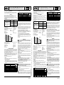
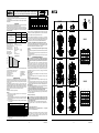
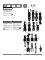
DESCRIPTION
Vannes télécommandées à clapet, 2/2 ou 3/2 :
- Série 298, NF- NO, et 398 U, corps taraudé PN 40, bride, embouts à souder
(emboîtement soudé).
Ces vannes sont équipées d'une tête de commande par piston
Ø80, Ø100, Ø150 ou Ø200 mm.
FONCTIONNEMENT
NF - Normalement Fermée : la vanne est fermée lorsque l'électrovanne-pilote
NF est hors-tension.
La vanne est ouverte lorsque l'électrovanne-pilote NF est sous-tension.
NO - Normalement Ouverte : la vanne est ouverte lorsque l'électrovanne-pilote
NF est hors-tension.
U - Universelle : Fonction mélangeuse (deux arrivées de pression en 1 ou 3, un
départ en 2) et distributrice (une arrivée de pression en 2, deux départs en 1 et 3)
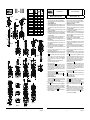
Fluides 298-398 :
fl uides plage de température
garniture
de clapet
DN 15-20-25 : air et gaz
groupes 1 & 2
DN 32-40-50 : air et gaz groupe 2
tous DN : eau, huile, liquides groupes 1
& 2 et vapeur d’eau
-10°C à +233°C PEEK
-10°C à +250°C métal/métal
-10°C à +180°C PTFE
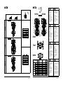
Caractéristiques techniques principales 298/398 :
Pression différentielle 0 à 40 bar
Pression maxi. admissible 40 bar (graphe I)
Plage de température ambiante
(version standard) -20°C..+180°C
Viscosité maxi. admissib
le 5000 cSt (mm
2
/s)
Contre-pression admissible tous fl uides 40 bar
vapeur saturée 24 bar
Fluide de pilotage air
Pression maxi. de pilotage 10 bar
Pression mini. de pilotage Pages : 7 (2/2); 8 (3/2)
100
40
20
40
24
21
233 250
t (°C)
P (bar)
graphe I
température fl uide
pression maxi.
Matériaux en contact avec le fl uide (Vérifi er la compatibilité du fl uide avec les
matériaux en contact)
Corps de vanne, bouchon, tige, clapet, siège Acier inox
Corps de presse-étoupe Acier inox
Garniture presse-étoupe PTFE chevrons
Garniture clapet PTFE ou PEEK
Joint de corps de vanne PTFE
MISE EN SERVICE
Les vannes sont conçues pour les domaines de fonctionnement indiqués sur la
plaque signalétique. Aucune modifi cation ne peut être réalisée sur le matériel
sans l’accord préalable du fabricant ou de son représentant. Avant de procéder
au montage, dépressuriser les canalisations et effectuer un nettoyage interne
des dites canalisations.
Lire les informations portées sur l'étiquette : code, orifi ce, fl uide (type, pression,
température), fl uide et pression de pilotage, et numéro de série.
ATTENTION : Ces vannes sont prévues, selon les modèles, pour fonctionner
avec certains fl uides.
Ne pas dépasser la limite de pression maximale admissible de la vanne. La
mise en service et l'entretien de la vanne doivent être réalisées par du person-
nel compétent.
Installation
Ces vannes peuvent être montées dans n'importe quelle position.
Raccordement
• Retirer le bouchon plastique de protection de l'orifi ce de raccordement du
pilotage et suivre la procédure de raccordement, selon les versions :
• Raccorder l'électrovanne de pilotage
- à l'orifi ce 1/8 (têtes Ø80, Ø100 mm) / 1/4 (têtes Ø150, Ø200 mm);
Respecter un couple de serrage (c) compris entre 4 et 5 Nm pour le raccordement
de pilotage.
• 2/2 : Orifi ce 1 (NF/NO), fonction anti-coup de bélier (recommandé sur fl uide
liquide).
DN
coeffi cient de débit Kv (2/2 NF-NO)
Ø tête
2
112
(m
3
/h) (l/min) (m
3
/h) (l/min)
(mm)
NF NO NF NO NF NO NF NO
15 5 3,5 83,33 58,33 4,4 3,5 73,33 58,33 80
20 8,5 7 141,66116,66 7,7 7,2 128,33 120 100
25 12 11 200 183,33 11,5 11 191,66 183,33 100
32 18 15 300 250 18 18 300 300 150
40 29 28,2 483,33 470 29 28,2 483,33 470 150
50 57 53 950 883,33 57 53 950 883,33 200
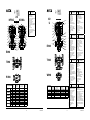
• 3/2 : Fonction mélangeuse, raccordement sur les orifi ces 1 et 3. Fonction
distributrice, sur l'orifi ce 2.
DN
coeffi cient de débit Kv (3/2 U)
Ø tête
mélangeuse distributrice
3
2122321
(m
3
/h) (l/min) (m
3
/h) (l/min) (m
3
/h) (l/min) (m
3
/h) (l/min) (mm)
15 3,3 54 4,4 73 3,5 59 4,6 78 80
20 8,0 133 7,4 123 8,1 136 7,7 129 100
25 11,4 190 11,6 194 12,1 203 11,9 199 100
32 18,9 316 16,6 278 17,9 299 16,6 278 150
40 27 450 27 450 27 450 27 450 150
50 51 850 51 850 51 850 51 850 200
Vannes à raccordement taraudé PN40 (298-398)
Raccorder les tuyauteries en fonction des repères marqués sur le corps et dans
cette documentation. Enduire légèrement de graisse (selon l'application) les
embouts femelles des tubes fi letés, ne pas enduire les taraudages mâles de la
vanne. Veiller à ce qu’aucun corps étranger ne pénètre dans le circuit.
Soutenir et aligner correctement les tuyauteries pour éviter toute contrainte
mécanique sur les vannes. Au serrage, ne pas se servir de la vanne comme
d'un levier; Positionner les clés de serrage sur le corps et sur les tubes aussi
près que possible du point de raccordement. Afi n d’éviter toute détérioration,
NE PAS TROP SERRER les raccords des tuyauteries.
Vannes à brides PN40, DIN et ANSI Classe 300 (298-398)
Brides PN40 type 21 (ISO 7005 - EN 1092), à raccorder avec un joint adapté
PN40 pour une pression nominale de 40 bar
, EN 558-1.
Versions ANSI class
300
ANSI B16-5, à brides, suivant norme ANSI B16-10.
Vannes à emboîtement soudé PN40 sur tube Ø ext. 22,4 à 62 mm (298-398)
Raccorder les emboîtements à souder en conformité avec la norme EN 12760
pour tube nor
malisé ISO 4200.
P
our les vannes NF (2/2), piloter l'actionneur afi n de supprimer le contact clapet/
siège de vanne pendant l'opération de soudure.
Pour les vannes U (3/2), lors de la soudure du corps s'assurer que le clapet ne
soit pas en contact avec le siège.
ENTRETIEN
!
Avant toute opération d'entretien ou de remise en marche, couper
l'alimentation du pilote, dépressuriser la vanne et la purger, pour prévenir
tout risque d'accident corporel ou matériel.
Nettoyage
L’entretien des vannes varie avec leurs conditions d’utilisation. Procéder à un net-
toyage périodique des vannes. L'intervalle entre deux nettoyages peut varier suivant
la nature du fl uide, les conditions de fonctionnement et le milieu ambiant. Lors de
l’intervention, les composants doivent être examinés pour détecter toute usure
excessive. Un nettoyage est nécessaire lorsqu'on observe un ralentissement de la
cadence alors que la pression de pilotage est correcte ou lorqu'un bruit anormal
ou une fuite est constaté. Au pire, un fonctionnement défectueux peut survenir et
la vanne ne plus s'ouvrir ou se fermer correctement.
Bruit de fonctionnement
L’utilisateur ne pourra déterminer avec précision le niveau sonore émis qu'après
avoir monté le composant sur l'installation.
Le bruit de fonctionnement varie selon l’utilisation, le fl uide et le type de matériel
employé.
Entretien préventif
• Faire fonctionner la vanne au moins une fois par mois pour
vérifi er son ouverture et sa fermeture.
• Des pochettes sont proposées en pièces de rechange pour procéder à la réfec-
tion. En cas de problème lors du montage/entretien ou en cas de doute, nous
contacter ou nos représentants offi ciels.
Conseils en dépannage :
• Pression de sortie incorrecte : Vérifi er la pression à l'entrée de la vanne,
elle doit correspondre aux valeurs admises sur l'étiquette d'identifi cation.
Attention, respecter les valeurs minimales de pression de pilotage en
fonctionnement NF-NO (2/2) ou U (3/2-mélangeuse et distributrice).
• Fuites : Démonter le corps de vanne et nettoyer ses parties internes. Utiliser les
pochettes de rechange pour remplacer, si nécessaire, les pièces concernées.
Démontage et remontage
!
Avant toute opération d'entretien, couper le réseau d'air de pilotage
et le circuit de vapeur, dépressuriser la vanne et la purger, pour prévenir
tout risque d'accident corporel ou matériel.
Cette opération s'effectue après démontage du corps de vanne de la tuyauterie.
V
eillez à ne pas introduire de cor
ps étrangers dans la vanne et tuyauterie pen-
dant cette intervention.
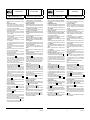
Procédure de démontage-remontage :
Pochettes : "I", voir fi
g. 1 à 6 / "II", voir fi g. 7 à 19 / "III", voir fi g. 20 à 41
!
Pour prévenir tout risque d'accident corporel ou matériel, vérifi er que la
vanne fonctionne correctement avant de la remettre en service. Vérifi er aussi
l'existence d'éventuelles fuites internes (sièges) ou externes avec un fl uide non-
explosible et ininfl ammable.
DESCRIPTION
Remote-controlled 2/2 or 3/2 valves:
- Series 298, NC- NO, and 398 U, threaded ports, PN 40, fl anges, socket welding.
The valves are equipped with a piston-type operator of dia. 80, 100, 150, or 200 mm.
FUNCTION
NC - Normally closed: The valve is closed when the NC pilot valve is idle.
The valve is open when the NC pilot valve is energised.
NO - Normally open: The valve is open when the NC pilot valve is idle.
U - Universal: Mixing function (two pressure supplies at 1 and 3, one outlet at 2) and
distributing (one pressure supply at 2, two outlets at 1 and 3).
Fluids, 298-398:
fl uids temperature range disc seal
DN 15-20-25: air and gas
groups 1 & 2
DN 32-40-50: air and gas group 2
all DN: water, oil, liquids groups 1 & 2
and steam
-10°C to +233°C PEEK
-10°C to +250°C metal-to-metal
-10°C to +180°C PTFE
Principal technical characteristics 298 - 398:
Differential pressure
0 to 40 bar
Max. allowable pressure 40 bar (see diagram I)
Ambient temperature range (standard version) -20°C..+180°C
Maximum viscosity 5000 cSt (mm
2
/s)
Allowable backpressure
All fl uids 40 bar
Saturated steam 24 bar
Pilot fl uid air
Max. pilot pressure
Max. pilot pressure 10 bar
Min. pilot pressure
Pages: 7 (2/2); 8 (3/2)
100
40
20
40
24
21
233 250
t (°C)
P (bar)
diagram I
fl uid temperature
max. pressure
Materials in contact with fl uid (verify to ensure the compatibility of the fl uid in
contact with the materials)
Valve body, plug, stem, disc, seat Stainless steel
Stuffi ng box body Stainless steel
Stuffi ng box packing PTFE chevrons
Disc seal PTFE or PEEK
Valve body ring PTFE
PUTTING INTO OPERATION
The valves are intended to be operated within the technical characteristics
specifi ed on the nameplate. Modifi cations to the products may only be made
after consulting the manufacturer or his representative. Before installation, de-
pressurise the piping system and clean internally.
Read all information on the label: code, port, fl uid (type, pressure, tempera-
ture), pilot fl uid, pilot pressure, serial number.
CAUTION: The valves must be operated with the fl uids intended for each version.
Do not exceed the max. allowable pressure of the valve. Installation and main-
tenance of the valve must be carried out by qualifi ed personnel only.
Fitting position
The valves may be mounted in any position.
Connection
• Remove the plastic protective plug from the pilot port and follow the connec-
tion procedures for each version.
• Connection of the pilot valve
- to the 1/8 port ((dia. 80, 100 mm operators) / to the 1/4 port (dia. 150, 200 mm opera-
tors); observe a tightening torque (c) between 4 and 5 Nm to connect the pilot valve.
•
2/2 : Port 1 (NC/NO), anti-waterhammer design (recommended for use with
liquids).
DN
fl ow coeffi cient Kv (2/2 NC-NO)
operator
dia.
2
112
(m
3
/h) (l/min) (m
3
/h) (l/min)
(mm)
NC NO NC NO NC NO NC NO
15 5 3,5 83,33 58,33 4,4 3,5 73,33 58,33 80
20 8,5 7 141,66116,66 7,7 7,2 128,33 120 100
25 12 11 200 183,33 11,5 11 191,66183,33 100
32 18 15 300 250 18 18 300 300 150
40 29 28,2 483,33 470 29 28,2 483,33 470 150
50 57 53 950 883,33 57 53 950 883,33 200
•
3/2 : Mixing function, connection to ports 1 and 3. Distributing function, connection to
port 2.
DN
fl ow coeffi cient Kv (3/2 U)
operator
dia.
mixing function distributing function
3
2122321
(m
3
/h) (l/min) (m
3
/h) (l/min) (m
3
/h) (l/min) (m
3
/h) (l/min) (mm)
15 3,3 54 4,4 73 3,5 59 4,6 78 80
20 8,0 133 7,4 123 8,1 136 7,7 129 100
25 11,4 190 11,6 194 12,1 203 11,9 199 100
32 18,9 316 16,6 278 17,9 299 16,6 278 150
40 27 450 27 450 27 450 27 450 150
50 51 850 51 850 51 850 51 850 200
Valves with internal thread connections PN40 (298-398)
Connect the piping as indicated on the body and in these instructions. Lightly
grease the female threads of the tapped pipes (depending on the application);
do not grease the male threads of the valve. Make sure that no foreign matter
enters the system.
Correctly support and align the pipes to prevent mechanical strain on the valve.
When tightening, do not use the valve as a lever; locate wrenches as close as
possible to the connection points on the valve body and pipes. To avoid damage
to the equipment, DO NOT OVERTIGHTEN pipe connections.
Valves with fl anges PN40, DIN and ANSI Class 300 (298-398)
Flange PN40 type 21 (ISO 7005 - EN 1092), to be connected with a PN40 seal suit-
able for a nominal pressure of 40 bar, EN 558-1. ANSI class 300 ANSI B16-5 versions
with fl anges in accordance with standard ANSI B16-10.
Valves with socket welding PN40 on tube OD. 22,4 to 62 mm (298-398)
Connect the socket weldings in accordance with standard EN 12760 for ISO 4200 tubes.
NC valves (2/2): pilot the operator to remove the contact between disc and seat
during welding.
U valves (3/2): When welding the body make sure the disc is not in contact
with the valve.
MAINTENANCE
!
Prior to any maintenance work or putting into operation, power off,
depressurise and vent the valve to prevent the risk of personal injury or
damage to equipment.
Cleaning
Maintenance of the valves depends on the operating conditions. They should
be cleaned at regular intervals. The intervals between two cleaning operations
may vary according to the nature of the fl uid, the working conditions and the
environment in which it is operated. During servicing, the components must be
checked for excessive wear. The components must be cleaned when a slowing
down of the cycle is noticed even though the pilot pressure is correct or if any
unusual noise or a leak is detected. At worst, this may lead to a malfunction of
the valve and it may not open and close correctly any more.
Sound emission
The exact determination of the sound level can only be carried out by the user
having the valve installed in his system.
The emission of sound depends on the application, medium and type of equip-
ment used.
Preventive maintenance
• Put the valve at least once a month into operation to check if it opens and
closes.
•
Spare parts kits are available for maintenance and repair. If problems arise during
maintenance or in case of doubt, please contact ASCO or one of its authorised
representatives.
Troubleshooting
• Incorrect outlet pressure: Check the pressure on the supply side of the
valve; it must correspond to the values indicated on the nameplate.
Caution: The minimum pilot pressure in NO -NC (2/2) function or U (3/2
- mixing or distributing function) must be observed.
• Leaks: Disassemble the valve body and clean the internal parts.
Use the spare
parts kits to replace worn or damaged parts, if necessary.
Disassembly and reassembly
!
Before any maintenance, disconnect the pilot from its control system
and the steam circuit, and depressurise and drain the valve to prevent the
risk of personal injury or damage to equipment.
These operations must be made after having disassembled the valve body
from the piping.
Make sure no foreign matter enters the valve and piping in the process.
Disassembly/reassembly procedure:
Spare parts kit: "I", see fi gs. 1 to 6 / "II", see fi gs. 7 to 19 / "III", see fi gs. 20 to 41
!
To avoid personal injury or property damage, check that the valve operates
correctly before putting it back into operation. Also check for possible internal or
external leaks (seats/discs) using a non-explosive and non-infl ammable fl uid.
526748-001 / A
Availability, design and specifi cations are subject to change without notice. All rights reserved.
La page est en cours de chargement...
La page est en cours de chargement...
La page est en cours de chargement...
La page est en cours de chargement...

526748-001 526748-001
12 13
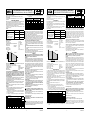
3/2 U
2
31
2
31
E398
3,2-DN 32
10
4,6
3,4
DN 20- 2,4
DN 25-1,1
0
10 20 30 40
P (bar)
p
(
bar
)
1,3-DN 25
1,4-DN 32
DN
4,7-DN 20
3,5-DN 25-40
2,4-DN 20
1,7-DN 15
(3ô2)
(1ô2)
DN 15-1,7
3,1-DN 15
32-1,4
DN 40-0,6
1
DN
50-1,3
3,9-DN 50
0,7-DN 40
1,2-DN 50
T398
3,0-DN 15
10
4,6
3,4
DN 20- 2,2
DN 25-0,8
0
10 20 30 40
P (bar)
p
(
bar
)
1,3-DN 25
1,4-DN 32
3,3-DN 20
3,4-DN
25
2,4-DN 20
1,7-DN 15
(2ô1)
(2ô3 )
DN 15-1,5
2,9-DN 32
DN 40-0,3
40
3,6-DN 50
0,75-DN 40
1,5-DN 50
DN
32
50
-1,1
W398
Ø 80 - 200
Ø 80 - 200
Ø 80 - 200
P
p
2
3
1
1
2
3
U
2
3
1
Ø 80 - 200
E298
E/T/W298
I
(No.-rep.-
Nr 1)
II (PTFE)
(No.-rep.-
Nr 1 .. 17)
III (PEEK)
(No.-rep.-
Nr 1 .. 17)
IV
(No.-rep.-
Nr 17)
Ø80 DN15
NC/NF
C140233 M29852671700100 M29852671400100 C140484
NO/NA
C140233 M29852671700200 M29852671400200 C140484
Ø100 DN20
NC/NF
C140234 M29852671700400 M29852671400400 C140485
NO/NA
C140234 M29852671700500 M29852671400500 C140485
Ø100 DN25
NC/NF
C140234 M29852671700700 M29852671400700 C140485
NO/NA
C140234 M29852671700800 M29852671400800 C140485
Ø150 DN32
NC/NF
C140235 M29852671701000 M29852671401000 C140486
NO/NA
C140235 M29852671701100 M29852671401100 C140486
Ø150 DN40
NC/NF
C140235 M29852671701300 M29852671401300 C140486
NO/NA
C140235 M29852671701400 M29852671401400 C140486
Ø200 DN50
NC/NF
C140298 M29852671701600 M29852671401600 C140487
NO/NA
C140298 M29852671701700 M29852671401700 C140487
GB
Designation
FR
Désignation
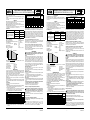
1. Piston seal + grease
2. Piston nut
3. Piston washer
4. Piston O-ring
5. Operator spring
6. Securing ring
7. Upper bearing
8. 2 O-rings
9. Valve body ring(s)
10. 2 stuffi ng box glands
11. 2 chevrons
12. 3 chevrons support
13. Stuffi ng box spring
Grease for stuffi ng box
14. Lower bearing
15. Reinforced disc
16. Stem
17. Cover
1. Joint de piston + graisse
2. Ecrou de piston
3. Rondelle de piston
4. Joint torique de piston
5. Ressort d’actionneur
6. Jonc
7. Palier haut
8. 2 joints toriques
9.
Joint(s) de corps de vanne
10. 2 fouloirs
11. 2 chevrons
12. 3 supports chevron
13. Ressort presse-étoupe
Graisse presse-étoupe
14. Palier bas
15. Clapet garni
16. Tige
17. Couvercle
DE
Bezeichnung
ES
Designación
1. Kolbendichtung + Fett
2. Kolbenmutter
3. Kolbenscheibe
4. Kolben-O-Ring
5. Antriebsfeder
6. Sicherungsring
7. Lager oben
8. 2 O-Ringe
9. Gehäusedichtung(en)
10. 2 Stopfbuchsenoberteil
11. 2 Dachmanschetten
12. 3 Dachmanschetten-
Unterstützung
13. Stopfbuchsenfeder
Fett f. Stopfbuchse
14.Unteres Lager
15. Ventilteller, verstärkt
16. Spindel
17. Deckel
1. Junta de pistón + grasa
2. Tuerca de pistón
3. Arandela de pistón
4. Junta tórica de pistón
5. Resorte de actuador
6. Arandela de retención
7. Casquillo alto
8. 2 juntas tóricas
9. Junta(s) de cuerpo de válvula
10. 2 Pisón
11. 2 chevrons
12. 3 soportes de chevron
13. Resorte prensa-estopas-
Grasa prensa-estopas
14. Casquillo bajo
15. Guarnición clapet
16. Vástago
17. Tapa
IT
Descrizione
NL
Aanduiding
1. Guarnizione del pistone +
grasso
2. Dado del pistone
3. Rondella del pistone
4. O-ring del pistone
5. Molla dell’attuatore
6. Anello di sicurezza
7. Guida superiore
8. 2 O-rings
9. Guarnizione(i) del corpo
10. 2 pressacavi per reci-
piente di riempimento
11. 2 angolari
12. 3 supporti angolari
13. Molla del premistoppa
Grasso per premistoppa
14.Cuscinetto inferiore
15. Disco rinforzat
16. Stelo
17. Coperchio
1. Zuigerafdichting + vet
2. Zuigermoer
3. Zuigerring
4. O-ring, zuiger
5. Stelveer
6. Borgring
7. Bovenste lager
8. 2 O-ringen
9. Afsluiterhuisring(en)
10. 2 Pakkingbusvulling
11. 2 chevrons
12. 3 3
ondersteunt chevron
13. Pakkingbusveer
Vet voor pakkingbus
14. Onderste lager
15. Versterkte klep
16. Spindel
17. Deksel
DK
Betegnelse
RU
Обозначение
1. Pakning til stempel + fedt
2. Møtrik til stempel
3. Spændskive til stempel
4. O-ring til spændskive
5. Fjeder til operator
6. Sikringsring
7. Øverste leje
8. 2 O-ringe
9. Ventilhusring(e)
10. 2 Stopbøsningsmuffe
11. 2 chevron-pakninger
12. 3 chevron-holder
13. Stopbøsningsfjeder
Stopbøsningsfedt
14. Nederste leje
15. Forstærket skive
16. Spindel
17. Låg
1. Уплотнитель поршня + смазка
2. Гайка поршня
3. Шайба поршня
4. Уплотнительное кольцо поршня
5. Пружина управляющего устрой-
ства
6. Стопорное кольцо
7. Верхний вкладыш подшипника
8. 2 уплотнительных кольца
9. Кольцо(-а) корпуса клапана
10. 2
крышку сальниковой камеры
11. 2
уплотнение chevron
12. 3
опору уплотнения chevron
13. Пружина сальниковой коробки
Смазка для сальниковой коробки
14. Нижний вкладыш подшипника
15. Диск с повышенной жесткостью
16. Шток
17. Крышка
T298
W298
NF/NC NO/NA
2/2
&
4
5
2
3
6
7
8
9
1
17
16
10
11
12
13
14
15
4
5
2
3
6
7
8
9

526748-001 526748-001
14 15
Ø 80 - 200
E298
KZ
Белгі
1. Поршень сақинасы + май
2. Поршень гайкасы
3. Поршень шайбасы
4. Поршеньнің О тəрізді сақинасы
5. Оператор серіппесі
6. Бекіту сақинасы
7. Жоғарғы мойынтірек
8. 2 О тəрізді сақина
9. Клапан корпусының сақина(лар)ы
10. 2
тығышдауыш қорабының
сальнигі
11. 2 шеврон
12. 3 шеврон
тірегі
13. Сальникті қорап серіппесі
Сальникті қорапқа арналған май
14. Төменгі мойынтірек
15. Тығыздалған диск
16.
Өзекті
17. Қақпақ
T298
W298
NF/NC NO/NA
2/2
&
4
5
2
3
6
7
8
9
1
17
16
10
11
12
13
14
15
4
5
2
3
6
7
8
9
E/T/W298
I
(No.-rep.-
Nr 1)
II (PTFE)
(No.-rep.-
Nr 1 .. 17)
III (PEEK)
(No.-rep.-
Nr 1 .. 17)
IV
(No.-rep.-
Nr 17)
Ø80 DN15
NC/NF
C140233 M29852671700100 M29852671400100 C140484
NO/NA
C140233 M29852671700200 M29852671400200 C140484
Ø100 DN20
NC/NF
C140234 M29852671700400 M29852671400400 C140485
NO/NA
C140234 M29852671700500 M29852671400500 C140485
Ø100 DN25
NC/NF
C140234 M29852671700700 M29852671400700 C140485
NO/NA
C140234 M29852671700800 M29852671400800 C140485
Ø150 DN32
NC/NF
C140235 M29852671701000 M29852671401000 C140486
NO/NA
C140235 M29852671701100 M29852671401100 C140486
Ø150 DN40
NC/NF
C140235 M29852671701300 M29852671401300 C140486
NO/NA
C140235 M29852671701400 M29852671401400 C140486
Ø200 DN50
NC/NF
C140298 M29852671701600 M29852671401600 C140487
NO/NA
C140298 M29852671701700 M29852671401700 C140487
Ø 80 - 200
E398
GB
Designation
FR
Désignation
1. Piston seal + grease
2. Piston nut
3. Piston washer
4. Piston O-ring
5. Operator spring
6. Securing ring
7. Upper bearing
8. 2 O-rings
9. Valve body ring(s)
10. 2 stuffi ng box glands
11. 2 chevrons
12. 3 chevrons support
13. Stuffi ng box spring
Grease for stuffi ng box
14. Lower bearing
15. Reinforced disc
16. Stem
17. Cover
1. Joint de piston + graisse
2. Ecrou de piston
3. Rondelle de piston
4. Joint torique de piston
5. Ressort d’actionneur
6. Jonc
7. Palier haut
8. 2 joints toriques
9. Joint(s) de corps de vanne
10. 2 fouloirs
11. 2 chevrons
12. 3 supports chevron
13. Ressort presse-étoupe
Graisse presse-étoupe
14. Palier bas
15. Clapet garni
16. Tige
17. Couvercle
DE
Bezeichnung
ES
Designación
1. Kolbendichtung + Fett
2. Kolbenmutter
3. Kolbenscheibe
4. Kolben-O-Ring
5. Antriebsfeder
6. Sicherungsring
7. Lager oben
8. 2 O-Ringe
9. Gehäusedichtung(en)
10. 2 Stopfbuchsenoberteil
11. 2 Dachmanschetten
12. 3 Dachmanschetten-
Unterstützung
13. Stopfbuchsenfeder
Fett f. Stopfbuchse
14. Unteres Lager
15. Ventilteller, verstärkt
16. Spindel
17. Deckel
1. Junta de pistón + grasa
2. Tuerca de pistón
3. Arandela de pistón
4. Junta tórica de pistón
5. Resorte de actuador
6. Arandela de retención
7. Casquillo alto
8. 2 juntas tóricas
9. Junta(s) de cuerpo de
válvula
10. 2 Pisón
11. 2 chevrons
12. 3 soportes de chevron
13. Resorte prensa-estopas-
Grasa prensa-estopas
14. Casquillo bajo
15. Guarnición clapet
16. Vástago
17. Tapa
IT
Descrizione
NL
Aanduiding
1. Guarnizione del pistone +
grasso
2. Dado del pistone
3. Rondella del pistone
4. O-ring del pistone
5. Molla dell’attuatore
6. Anello di sicurezza
7. Guida superiore
8. 2 O-rings
9. Guarnizione(i) del corpo
10. 2 pressacavi per reci-
piente di riempimento
11. 2 angolari
12. 3 supporti angolari
13. Molla del premistoppa
Grasso per premistoppa
14. Cuscinetto inferiore
15. Disco rinforzat
16. Stelo
17. Coperchio
1. Zuigerafdichting + vet
2. Zuigermoer
3. Zuigerring
4. O-ring, zuiger
5. Stelveer
6. Borgring
7. Bovenste lager
8. 2 O-ringen
9. Afsluiterhuisring(en)
10. 2 Pakkingbusvulling
11. 2 chevrons
12. 3
ondersteunt chevron
13. Pakkingbusveer
Vet voor pakkingbus
14. Onderste lager
15. Versterkte klep
16. Steel
17. Deksel
DK
Betegnelse
RU
Обозначение
1. Pakning til stempel + fedt
2. Møtrik til stempel
3. Spændskive til stempel
4. O-ring til spændskive
5. Fjeder til operator
6. Sikringsring
7. Øverste leje
8. 2 O-ringe
9. Ventilhusring(e)
10. 2 Stopbøsningsmuffe
11. 2 chevron-pakninger
12. 3 chevron-holder
13. Stopbøsningsfjeder
Stopbøsningsfedt
14. Nederste leje
15. Forstærket skive
16. Spindel
17. Låg
1. Уплотнитель поршня + смазка
2. Гайка поршня
3. Шайба поршня
4. Кольцевое уплотнение поршня
5. Пружина управляющего устройства
6. Стопорное кольцо
7. Верхний вкладыш подшипника
8. 2 уплотнительных кольца
9. Кольцо(-а) корпуса клапана
10. 2
крышку сальниковой камеры
11. 2
уплотнение chevron
12. 3
опору уплотнения chevron
13. Пружина сальниковой коробки
Смазка для сальниковой коробки
14. Нижний вкладыш подшипника
15. Диск с повышенной жесткостью
16. Шток
17. Крышка
T398
W398
E/T/W398
I
(No.-rep.-
Nr 1)
II (PTFE)
(No.-rep.-
Nr 1 .. 17)
III (PEEK)
(No.-rep.-
Nr 1 .. 17)
IV
(No.-rep.-
Nr 17)
Ø 80 DN15 C140233
M39852671700300 M39852671400300
C140484
Ø 100 DN20 C140234
M39852671700600 M39852671400600
C140485
Ø 100 DN25 C140234
M39852671700900 M39852671400900
C140485
Ø 150 DN32 C140235
M39852671701200 M39852671401200
C140486
Ø 150 DN40 C140235
M39852671701500 M39852671401500
C140486
Ø 200 DN50 C140298
M39852671701800 M39852671401800
C140487
3/2
U
&
4
5
2
3
6
7
8
9
17
1
16
10
11
12
13
14
15

526748-001 526748-001
16 17
Ø 80 - 200
KZ
Белгі
1. Поршень сақинасы + май
2. Поршень гайкасы
3. Поршень шайбасы
4. Поршеньнің О тəрізді сақинасы
5. Оператор серіппесі
6. Бекіту сақинасы
7. Жоғарғы мойынтірек
8. 2 О тəрізді сақина
9. Клапан корпусының сақина(лар)ы
10. 2 Сальникті қорап қақпағы
11. 2 шеврон
12. 3 шеврон support
13. Сальникті қорап серіппесі
Сальникті қорапқа арналған май
14. Төменгі мойынтірек
15. Тығыздалған диск
16.
Өзекті
17. Қақпақ
&
E398
T398
W398
3/2
U
4
5
2
3
6
7
8
9
17
1
16
10
11
12
13
14
15
E/T/W398
I
(No.-rep.-
Nr 1)
II (PTFE)
(No.-rep.-
Nr 1 .. 17)
III (PEEK)
(No.-rep.-
Nr 1 .. 17)
IV
(No.-rep.-
Nr 17)
Ø 80 DN15 C140233
M39852671700300 M39852671400300
C140484
Ø 100 DN20 C140234
M39852671700600 M39852671400600
C140485
Ø 100 DN25 C140234
M39852671700900 M39852671400900
C140485
Ø 150 DN32 C140235
M39852671701200 M39852671401200
C140486
Ø 150 DN40 C140235
M39852671701500 M39852671401500
C140486
Ø 200 DN50 C140298
M39852671701800 M39852671401800
C140487
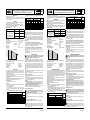
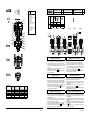
Fig. 1 Fig. 2 Fig. 3 Fig. 4 Fig. 5 Fig. 6
17
A
1
1
Ø80-100 = 5 mm
Ø150 = 6 mm
Ø200 = 8 mm
2/2
3/2
2/2
3/2
2/2
3/2
2/2
3/2
17
A
a
2/2
3/2
SPARE PARTS KIT
GB
DEMONTAGE-REMONTAGE
FR
ERSATZTEILPACKUNG
DE
BOLSAS DE RECAMBIO
ES
PARTI DI RICAMBIO
IT
VERVANGINGSSET
NL
No.
rep.
Nr
Ø
F
(mm)
(mm) N.m Inch.Pounds
a
80 - 100 8 70.81 5
150 10 88.51 6
200 20 177.01 8
I
1. Dévisser les quatre vis (A) et enlever leurs écrous.
Déposer le couvercle supérieur (17) et le joint (1) (Fig. 1-2-3).
2.
Nettoyer le piston et l’intérieur du tube de tête de commande (Fig. 4).
3. Graisser l’intérieur du tube sur la zone en contact avec le joint de
piston (graisse fournie) et positionner le joint neuf (1) (Fig. 4).
4. Remonter le couvercle supérieur neuf (17) avec les quatre vis
(A) et leurs écrous, serrer le tout au couple
a
(Fig. 5).
5. Admettre la pression de pilotage (10 bar) pour terminer la mise
en place du joint de piston (Fig. 6).
GB (spare parts kit I ) ES (bolsas de recambio I )
FR (pochette I ) IT (parti di ricambio I )
DE (Ersatzteilpackung I ) NL (reserveonderdelenset I )
1. Unscrew the 4 screws (A) and remove the nuts.
Remove the upper cover (17) and the seal (1) (Fig. 1-2-3).
2. Clean the piston and the interior of the operator tube
(Fig. 4).
3. Grease the interior of the tube which comes into contact with
the piston seal (grease supplied) and position the new seal (1)
(Fig. 4).
4. Remount the new upper cover (17) with the 4 screws (A) and
nuts and tighten the unit to torque
a
(Fig. 5).
5. Apply the pilot pressure (10 bar) to complete the installation of
the piston seal (Fig. 6).
1. Lösen Sie die 4 Schrauben (A) und entfernen Sie die Muttern.
Entfernen Sie den oberen Deckel (17) und die Dichtung (1) (Abb. 1-2-3).
2. Reinigen Sie den Kolben und das Innere des Führungsrohres für den
Steuerantrieb (Abb.4).
3. Fetten Sie das Innere des Führungsrohres an der Stelle ein, die mit der
Kolbendichtung in Berührung kommt (Fett im Lieferumfang enthalten) und
legen Sie die neue Dichtung ein (1) (Abb. 4).
4. Montieren Sie den neuen oberen Deckel (17) mit den 4 Schrauben (A) und
Muttern und ziehen Sie die Einheit mit dem Moment
a
fest (Abb. 5).
5. Beaufschlagen Sie die Einheit mit dem Steuerdruck (10 bar), um die
Installation der Kolbendichtung abzuschließen (Abb. 6).
1. Togliere le 4 viti (A) e rimuovere i dadi.
Rimuovere il coperchio (17) e la guarnizione (1) (Fig. 1-2-3).
2. Pulire il pistone e l'interno della testa di comando. 4).
3. Lubrifi cre l'interno della testa di comando sulla zona a contatto con la
guarnizione del pistone (grasso fornito) e posizionare la nuova guarni-
zione (1) (Fig. 4).
4. Rimontare il nuovo coperchio superiore (17) con le 4 viti (A) e i dadi,
procedere con il serraggio con coppia
a
(Fig. 5).
5. Utilizzare la pressione di pilotaggio (10 bar) per completare l'installazione
della guarnizione del pistone
(Fig. 6).
1. Desenrosque los cuatro tornillos (A) y suelte sus tuercas.
Desmonte la tapa superior (17) y la junta (1) (Fig. 1-2-3).
2.
Limpie el pistón y el interior del tubo de cabeza de mando (Fig. 4).
3. Engrase el interior del tubo en la zona en contacto con la junta
de pistón (grasa provista) y posicione la junta nueva(1) (Fig. 4).
4. Vuelva a montar la tapa superior nueva (17) con los cuatro tor-
nillos (A) y sus tuercas, apretar todo al par
a
(Fig. 5).
5. Aplicar una presión de pilotaje (10 bar) para completar la colo-
cación de la junta de pistón (Fig. 6).
1. Draai de 4 schroeven (A) los en verwijder de moeren.
Verwijder het bovendeksel (17) en de afdichting (1) (Fig. 1-2-3).
2. Reinig de zuiger en de binnenkant van de buis van de bedie-
ningskop
(Fig. 4).
3. Vet de binnenkant van de buis in die in contact komt met de zui-
gerafdichting (vet geleverd) en positioneer de nieuwe afdichting
(1) (Fig. 4).
4. Hermonteer het nieuwe bovendeksel (17) met de 4 schroeven (A)
en de moeren en draai de eenheid vast volgens het aandraaikop-
pel
a
(Fig. 5).
5. Pas de stuurdruk toe (10 bar) om de installatie van de zuigeraf-
dichting te voltooien (Fig. 6).
La page est en cours de chargement...

526748-001 526748-001
20 21
6
7
8
10
11
12
13
14
8
16
15
2
3
4
G
G
J
J
J
16
15
10
11
12
13
14
8
9
9
E
B
B
E
E
F
F
A
E
E
L
L
c
c
d
2
3
4
G
2
3
4
b
b
b
H
I
5
a
17
17
1
9
D
B
c
d
NC/NF NO/NA
NC/NF
U
NO/NA
Fig. 29
Fig. 31
Fig. 32
Fig. 33
Fig. 34
Fig. 35
Fig. 36
Fig. 37
Fig. 38
Fig. 30
No.
rep.
Nr
Ø
F
(mm)
(mm) N.m
Inch.Pounds
a
80 - 100 8 70.81 5 -
150 10 88.51 6 -
200 20 177.01 8 -
b 80-100-150-200 8 70.81 - 8
c
80 6,5 57.33 4 -
100 10 88.20 5 -
150 24 211.68 6 -
200 55 485.10 8 -
d
80 30 265.52 - 17
100 (DN 20) 30 265.52 - 20
100 (DN 25) 30 265.52 - 38
150 (DN 32) 35 309.77 - 38
150 (DN 40) 35 309.77 - 54
200 (DN 50) 35 309.77 - 60
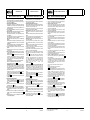
Fig. 31
II - III
GB (spare parts kit II - III) FR (pochette II - III)
1. Unscrew the 4 screws (A) and the nuts
(Fig. 20)
.
Remove the upper cover (17) and the seal (1)
(Fig. 21-22).
2. Unscrew the plug (2/2) or the body for way 3 (3/2) (D) and remove
the O-ring (9) (Fig. 23).
3. Caution: spring under load.
Firmly hold the piston (G) and the valve assembly. Unscrew the
piston nut while holding the disc nut (F). Dislodge the piston from
its hold and remove the nut (2), the washer (3) and the seal (4)
(Fig. 24).
4. Remove the piston (G), the indicator (H) and its spring (I), the
operator spring (5) (Fig. 25).
5. NC and U versions: Remove the stem/disc unit (15-16) from
the valve body (E) and unscrew the operator body (L) (Fig. 26).
Disassemble the stuffi ng box unit and remove all the internal
components (Fig. 26).
Unscrew the fastening screws (B) for the stuffi ng box body (J)
and remove the stuffi ng box and the O-ring (9) (Fig. 26).
NO-version: Unscrew the operator body (L) from the valve
body (E) (Fig. 27).
Unscrew the fastening screws (B) for the stuffi ng box (J) and
remove the stuffi ng box/stem/disc unit (J-15-16) from the valve
body (E) (Fig. 27).
Disassemble the stuffi ng box unit, remove all the internal com-
ponents and remove the stem/disc unit (15-16) (Fig. 27).
6. Remove (L) the securing ring (6), the upper bearing (7) and the
O-ring (8) (Fig. 28).
7. Remount the new parts: the upper bearing (7), the securing
ring (6), and the O-ring (8) (Fig. 29).
8. NC and U versions (Fig. 31): Remount the new O-ring (9) and
tighten the stuffi ng box body (J) with the screws (B) to torque
c
.
Remount the new parts in the stuffi ng box: the lower bearing
(14), the O-ring (8), 1 chevron support (12), the spring (13),
1 chevron support (12) , 1 chevron (11), 1 stuffi ng box gland
(10), 1 chevron support (12), 1 chevron (11) et 1 stuffi ng box
gland (10).
Screw tight the operator body unit (L)/Valve (E) by hand.
Replace the new stem/disc unit (15-16).
Finish screwing to torque .
Version NO (Fig. 30): Remount the new parts in the stuff-
ing box body: lower bearing (14), O-ring (8), 1 chevron sup-
port (12), spring (13), 1 chevron support (12), 1 chevron (11),
1 stuffi ng box gland (10), 1 chevron support (12), 1 chevron
(11) and 1 stuffi ng box gland (10). Fit the unit thus formed on
the stem/disc (15-16).
Remount the new seal (9) and tighten the stuffi ng box body (J)
with the screws (B) to torque
c
.
Tighten the operator body (L)/valve (E) unit to torque
d
.
9. Remount the indicator (H) and its spring (I), and the operator
spring (5) (Fig. 32-33).
10. Caution: spring under load.
Replace and insert the seal (4) and the washer (3) and tighten
the nut (2) to torque
b
while fi rmly holding the piston (G) with
the valve assembly and disc nut (F) (Fig. 34).
11. NC version: Replace the O-ring (9) and tighten the plug (D) to
torque
c
(Fig. 35).
12. Clean the piston and the interior of the operator tube (Fig. 36).
13. Grease the interior of the tube which comes into contact with the
piston seal (grease supplied) and position the seal (1) (Fig. 36).
14. Remount the new upper cover (17) with the 4 screws (A) and
nuts and tighten the unit to torque
a
(Fig. 37).
15. Apply the pilot pressure (10 bar) to complete the installation of
the piston seal (Fig. 38).
1. Dévisser les quatre vis (A) et leurs écrous
(Fig. 20)
.
Déposer le couvercle supérieur (17) et le joint (1) (Fig. 21-22).
2. Dévisser le bouchon (2/2) ou le corps de la 3ème voie rapportée
(3/2) (D) et enlever le joint torique (9) (Fig. 23).
3. Attention ressort en charge.
Maintenir fermement le piston (G) avec l'ensemble de la vanne.
Puis dévisser l'écrou de piston en tenant l'écrou de clapet (F).
Libérer le piston de son maintien et enlever l'écrou (2), la rondelle
(3) et le joint (4) (Fig.24).
4. Ensuite enlever le piston (G), l'indicateur (H) son ressort (I), et
le ressort d'actionneur (5) (Fig. 25).
5. Version NF et U : déposer l'ensemble tige/clapet (15-16) du
corps de vanne (E), dévisser le corps d'actionneur (L) (Fig. 26).
Démonter l’ensemble presse étoupe et retirer tous les compo-
sants internes (Fig. 26).
Dévisser les vis (B) maintenant le corps du presse étoupe (J),
le déposer ainsi que le joint torique (9) (Fig. 26).
Version NO : dévisser le corps de l'actionneur (L) du corps de
vanne (E) (Fig. 27).
Dévisser les vis (B) maintenant le presse étoupe (J) et séparer
l'ensemble presse étoupe/tige/clapet (J-15-16) du corps de
vanne (E) (Fig. 27).
Démonter l’ensemble presse étoupe, retirer tous les composants
internes et déposer l'ensemble tige/clapet (15-16) (Fig. 27).
6. Démonter (L) le circlips (6), le palier haut (7) et le joint torique (8)
(Fig. 28).
7. Remonter (pièces neuves), le palier haut (7), le circlips (6), et le
joint torique (8) (Fig. 29).
8. Version NF et U (Fig. 31) : Remonter le nouveau joint torique
(9), et fi xer le corps du presse étoupe (J) à l'aide des vis (B)
au
couple
c
.
Remonter dans le presse étoupe les nouvelles pièces : le palier
bas (14), le joint torique (8), 1 support de chevron (12), le ressort
(13), 1 support de chevron (12) , 1 chevron (11), 1 fouloir (10),
1 support de chevron (12), 1 chevron (11) et 1 fouloir (10).
Visser l'ensemble corps d'actionneur (L) /Vanne (E) à la main.
Remettre en place le nouvel ensemble Tige/Clapet (15-16).
Finir de visser au couple
d
.
Version NO (Fig. 30) :
Remonter dans le corps du presse étoupe
les nouvelles pièces : le palier bas (14), le joint torique (8),
1 support de chevron (12), le ressort (13), 1 support de chevron
(12) , 1 chevron (11), 1 fouloir (10), 1 support de chevron (12),
1 chevron (11) et 1 fouloir (10). Emmancher l'ensemble ainsi
formé sur la Tige/Clapet (15-16).
Remonter le nouveau joint (9) et fi xer le presse étoupe (J) à l'aide
des vis (B)
au couple
c
.
Revisser l'ensemble corps d'actionneur (L) / Vanne (E) au couple
d
.
9. Remonter l'indicateur (H) et son ressort (I), puis le ressort
d'actionneur (5) (Fig. 32-33).
10. Attention ressort en charge.
Remplacer le joint (4), la rondelle (3) et visser l'écrou (2) au
couple
b
en maintenant fermement le piston (G) avec l'en-
semble de la vanne et l'écrou de clapet (F) (Fig. 34).
11. Remplacer le joint torique (9) et visser le bouchon (2/2) ou le
corps de la 3ème voie rapportée (3/2) (D) au couple
c
(Fig. 35).
12. Nettoyer le piston et l’intérieur du tube de tête de commande
(Fig. 36).
13. Graisser l’intérieur du tube sur la zone en contact avec le joint
de piston (graisse fournie) et positionner le joint (1) (Fig. 36).
14. Remonter le nouveau couvercle supérieur (17) avec les quatre
vis (A) et leurs écrous, serrer le tout au couple
a
(Fig. 37).
15. Admettre la pression de pilotage (10 bar) pour terminer la mise
en place du joint de piston (Fig. 38).
SPARE PARTS KIT
GB
POCHETTE DE RECHANGE
FR
d
La page est en cours de chargement...
La page est en cours de chargement...
La page est en cours de chargement...
La page est en cours de chargement...
La page est en cours de chargement...
-
 1
1
-
 2
2
-
 3
3
-
 4
4
-
 5
5
-
 6
6
-
 7
7
-
 8
8
-
 9
9
-
 10
10
-
 11
11
-
 12
12
-
 13
13
-
 14
14
-
 15
15


Asco Series 298 398 Pressure Operated Valves Guide d'installation
- Taper
- Guide d'installation
dans d''autres langues
- italiano: Asco Series 298 398 Pressure Operated Valves Guida d'installazione
- English: Asco Series 298 398 Pressure Operated Valves Installation guide
- español: Asco Series 298 398 Pressure Operated Valves Guía de instalación
- Deutsch: Asco Series 298 398 Pressure Operated Valves Installationsanleitung
- русский: Asco Series 298 398 Pressure Operated Valves Инструкция по установке
- Nederlands: Asco Series 298 398 Pressure Operated Valves Installatie gids
- dansk: Asco Series 298 398 Pressure Operated Valves Installationsvejledning
Documents connexes
-
Asco Series 290 Valves for Control in Wine Tanks Le manuel du propriétaire
-
-
-
-
-
-
-
-
-
Autres documents
-
 Multi-Contact XZGL425SW Guide d'installation
-
sauter VUP Assembly Instructions
-
Ascon tecnologic VM Le manuel du propriétaire
-
Honeywell Trousses d’ Mode d'emploi
-
Dometic Optima Mode d'emploi
-
Hauck Nécessaires de bride de vanne de la série SV2 Mode d'emploi
-
ACV Compact Condens Technical Manual
-
Burkert 2730 Series Operating Instructions Manual
-
SCOTT 09989 Mode d'emploi
-
Johnson Controls VP1000 Series Manuel utilisateur
