
100 Amp / 200 Amp
Automatic Transfer Switch
with Service Disconnect &
AC Power Control Module™
Installation and Operator’s Manual
TS100A, TS100AD, TS200A, TS200AD
Questions?
Help is just a moment away!
Call: Transfer Switch Helpline
(877) 369-9400 M-F 8-5 CT
071028 & 071029 202213GS Rev. - (01/04/2007)

Thank you for your purchase of this Rheem/Ruud Automatic Transfer Switch. This product is intended for use with Rheem
and Ruud Home Standby Generator sets ONLY. This is an optional home standby system which provides an alternate source
of electric power and to serve loads such as a gas furnace, refrigeration and communication systems that, when stopped
during any power outage, could cause discomfort, or the like.
This manual contains safety information to make you aware of the hazards and risks associated with transfer switches and
how to avoid them. Rheem has made every effort to provide for a safe, streamlined and cost-effective installation. Each
installation is unique, it is impossible to know of and advise of all conceivable procedures and methods by which installation
might be achieved. We do not know all possible hazards and/or the results of each method or procedure. Save these
instructions for future reference.
This transfer switch requires installation before use. Refer to the Installation section of this manual for instructions on
installation procedures. Only licensed electrical contractors should install transfer switches. Installations must strictly
comply with all applicable federal, state and local codes, standards and regulations.
Where to Find Us
You never have to look far to find support and service for your transfer switch. Consult your Yellow Pages. There are many
Rheem and Ruud authorized service dealers who provide quality service. You can also contact Rheem/Ruud Customer Service
by phone at (877) 369-9400.
Transfer Switch
Model Number
Revision
Serial Number
Date Purchased
Rheem Sales Company
Randleman, NC 27317
(877) 369-9400
Copyright © 2007 Rheem Sales Company. All rights
reserved. No part of this material may be reproduced or
transmitted in any form by any means without the express
written permission of Rheem Sales Company.

1
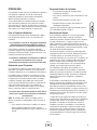
FrançaisEspañol
Important Safety Instructions . . . . . . . . . . . . . . . . . . . . . . . . . . . . . . . . . 2
Owner Orientation . . . . . . . . . . . . . . . . . . . . . . . . . . . . . . . . . . . . . . . . . . . . 3
Installer Responsibilities . . . . . . . . . . . . . . . . . . . . . . . . . . . . . . . . . . . . . . . 3
Equipment Description. . . . . . . . . . . . . . . . . . . . . . . . . . . . . . . . . . . . . . . . . 3
Installation . . . . . . . . . . . . . . . . . . . . . . . . . . . . . . . . . . . . . . . . . . . . . 4
Unpacking . . . . . . . . . . . . . . . . . . . . . . . . . . . . . . . . . . . . . . . . . . . . . . . . . . 4
Mounting Guidelines . . . . . . . . . . . . . . . . . . . . . . . . . . . . . . . . . . . . . . . . . . 4
Power Wiring Interconnections . . . . . . . . . . . . . . . . . . . . . . . . . . . . . . . . . . 5
Supervisory Control Wiring . . . . . . . . . . . . . . . . . . . . . . . . . . . . . . . . . . . . . 6
System Setup. . . . . . . . . . . . . . . . . . . . . . . . . . . . . . . . . . . . . . . . . . . . . . . . 7
Controls . . . . . . . . . . . . . . . . . . . . . . . . . . . . . . . . . . . . . . . . . . . . . . . 7
Operation . . . . . . . . . . . . . . . . . . . . . . . . . . . . . . . . . . . . . . . . . . . . . . 7
Testing the Automatic Transfer Switch . . . . . . . . . . . . . . . . . . . . . . . . . . . . 7
Maintenance . . . . . . . . . . . . . . . . . . . . . . . . . . . . . . . . . . . . . . . . . . . . 8
Specifications. . . . . . . . . . . . . . . . . . . . . . . . . . . . . . . . . . . . . . . . . . . . . . . . 8
Troubleshooting . . . . . . . . . . . . . . . . . . . . . . . . . . . . . . . . . . . . . . . . . . 9
Transfer Switch Schematic Diagram . . . . . . . . . . . . . . . . . . . . . . . . . . . . . 10
Transfer Switch Wiring Diagram . . . . . . . . . . . . . . . . . . . . . . . . . . . . . . . . 11
Warranty . . . . . . . . . . . . . . . . . . . . . . . . . . . . . . . . . . . . . . . . . . . . . . 12
Table of Contents

2
Important Safety Instructions
This is the safety alert symbol. It is used to alert
you to potential personal injury hazards. Obey all
safety messages that follow this symbol to avoid
possible injury or death.
The safety alert symbol ( ) is used with a signal word
(DANGER, CAUTION, WARNING), a pictorial and/or a safety
message to alert you to hazards. DANGER indicates a hazard
which, if not avoided, will result in death or serious injury.
WARNING indicates a hazard which, if not avoided, could
result in death or serious injury. CAUTION indicates a hazard
which, if not avoided, might result in minor or moderate
injury. NOTICE indicates a situation that could result in
equipment damage. Follow safety messages to avoid or
reduce the risk of injury or death.
The manufacturer cannot possibly anticipate every possible
circumstance that might involve a hazard. The warnings in
this manual, and the tags and decals affixed to the unit are,
therefore, not all-inclusive. If you use a procedure, work
method or operating technique that the manufacturer does
not specifically recommend, you must satisfy yourself that it
is safe for you and others. You must also make sure that the
procedure, work method or operating technique that you
choose does not render the transfer switch unsafe.
Save These Instructions
• Use transfer switch only for intended uses.
• If you have questions about intended use, ask dealer or contact
Rheem.
• Do not expose transfer switch to excessive moisture, dust, dirt,
or corrosive vapors.
• Remain alert at all times while working on this equipment. Never
work on the equipment when you are physically or mentally
fatigued.
• If connected devices overheat, turn them off and turn off their
circuit breaker/fuse.
NOTICE
Improper treatment of transfer switch can damage it and
shorten its life.
• Do not touch bare wires.
• Do not use transfer switch with worn, frayed, bare or otherwise
damaged wiring.
• Do not handle electrical cords while standing in water, while
barefoot, or while hands or feet are wet.
• If you must work around a unit while it is operating, stand on an
insulated dry surface to reduce shock hazard.
• Do not allow unqualified persons or children to operate or
service transfer switch.
• In case of an accident caused by electrical shock, immediately
shut down all sources of electrical power and contact local
authorities. Avoid direct contact with the victim.
WARNING
Failure to properly ground transfer switch can
result in electrocution.
• Despite the safe design of the transfer switch, operating this
equipment imprudently, neglecting its maintenance or being
careless can cause possible injury or death.
WARNING
Transfer switch contains high voltage that can
cause personal injury or death.
• Failure to follow above warning could cause personal injury,
damage and/or malfunction of equipment.
WARNING
Low voltage wire cannot be installed in same
conduit as power voltage wiring.
WARNING
Only qualified electricians should attempt installation of
this system, which must strictly comply with applicable
codes, standards and regulations.

3
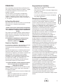
Introduction
Your Rheem/Ruud Transfer Switch is supplied with this
combined “Installation and Operator’s Manual”. This is an
important document and should be retained by the owner
after the installation has been completed.
Every effort has been expended to make sure that the
information in this manual is both accurate and current.
However, the manufacturer reserves the right to change, alter
or otherwise improve the system at any time without prior
notice.
For the Home Owner
To help you make informed choices and communicate
effectively with your installation contractor(s),
Read and understand the Owner Orientation Section
of this manual BEFORE contracting or starting your
transfer switch installation.
To arrange for proper installation, contact the store at which
you purchased your Rheem/Ruud transfer switch, your
dealer, or your utility power provider.
The Transfer Switch Warranty is VOID
unless the system is installed by a
licensed electrical professional.
Owner Orientation
The illustrations are for typical circumstances and are meant
to familiarize you with the installation options available with
your transfer switch.
Local codes, appearance, and distances are the factors that
must be considered when negotiating with an installation
professional. As the distance from the existing electrical
service increases, compensation in wiring materials must be
allowed for. This is necessary to comply with local codes and
overcome electrical voltage drops.
The factors mentioned above will have a direct effect on the
overall price of your transfer switch installation.
NOTE: Your installer must check local codes AND obtain
permits before installing the system.
• Read and follow the instructions given in this manual.
• Follow a regular schedule in caring for and using your
transfer switch, as specified in the manual.
Installer Responsibilities
• Read and observe the safety rules.
• Read and follow the instructions given in this manual.
• Check federal, state and local codes and authority
having jurisdiction, for questions on installation.
• Ensure generator is not overloaded with selected loads.
If you need more information about the transfer switch, call
(877) 369-9400, between 8:00 AM and 5:00 PM CT.
Equipment Description
The transfer switches are intended to transfer the entire load
of normal residential installations when used with the
supervisory contacts provided. The load is connected either
to utility power (normal) or home standby power
(generator). The transfer switch monitors utility and
generator voltages and will automatically connect to the
appropriate source of power.
These switches make it easy for a licensed electrician to
complete a home standby installation. The unit contains
utility service disconnect circuit breaker, generator
disconnect circuit breaker and automatic transfer switch in
one enclosure. Service conduit and conductors can be wired
directly from your meter to the transfer switch. A separate
disconnect and associated wiring are not required when
installed per applicable federal, state and local codes,
standards and regulations.
Major components of the transfer switch are a 2 pole utility
disconnect circuit breaker, a 2 pole generator disconnect
circuit breaker, a 2 pole double throw transfer switch, control
circuit board, fused utility terminals and interconnecting
wiring. The control board also has two inputs for current
transformers that sense generator current.
The transfer switch is solenoid-operated from utility or
generator inputs and contain suitable mechanical and
electrical interlock switches to eliminate the possibility of
connecting the utility service to the generator output. It has
ratings capable of switching full utility power into the
residence. In addition, a manual override lever is provided
for the transfer function.
The control circuit board has active circuits sensing utility
and generator voltages. It creates a signal for the generator
start-up, switch transfer and retransfer when utility is
restored. The control board also contains red and green
LED’s indicating the power sources available and two relay
operated contacts that provide supervisory control of
external loads.

4
Installation
Unpacking
Delivery Inspection
After removing the carton, carefully inspect the transfer
switch components for any damage that may have occurred
during shipment.
IMPORTANT: If loss or damage is noted at time of delivery,
have the person(s) making delivery note all damage on the
freight bill and affix his signature under the consignor's
memo of loss or damage. If loss or damage is noted after
delivery, contact the carrier for claim procedures. Missing or
damaged parts are not warranted.
Shipment Contents
• Automatic Power Transfer Switch
• Installation and Operator’s Manual
Mounting Guidelines
The Automatic Transfer Switch is enclosed in a NEMA
Type 3R enclosure suitable for indoor/outdoor use.
Guidelines for mounting the Automatic Transfer Switch
include:
• Install the switch on a firm, sturdy supporting structure.
• The switch must be installed with minimum NEMA 3R
hardware for conduit connections.
• To prevent switch contact distortion, level and plumb the
enclosure. This can be done by placing washers between
the switch enclosure and the mounting surface.
• NEVER install the switch where any corrosive
substance might drip onto the enclosure.
• Protect the switch at all times against excessive moisture,
dust, dirt, lint, construction grit and corrosive vapors.
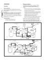
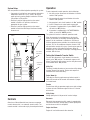
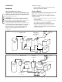
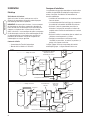
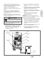
A typical and an alternative installation of the Automatic
Power Transfer Switch is depicted below. It is best if the
transfer switch is mounted near the utility meter, either
inside or outside. Discuss layout suggestions/ changes with
the owner before beginning the system installation process.
Main
Breaker
Panel
Transfer
Switch w/
Service and
Generator
Disconnect
Hot
Water
Heater
Air
Conditioner
Contactor
Generator
Watt -
Hourmeter
Typical
Branch
Circuits
— — — — — — Control Wiring
Disconnect Switch
Main
Breaker
Panel
Transfer
Switch
Hot
Water
Heater
Air
Conditioner
Contactor
Disconnect Switch
Generator
Watt -
Hourmeter
Branch
Circuits
Emergency
Branch
Circuits
— — — — — — Control Wiring
Emergency
Load
Center
Alternate

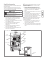
Power Wiring Interconnections
All wiring must be the proper size, properly supported and
protected by conduit.
Complete the following connections between the transfer
switch, main distribution panel, utility power and generator,
as shown on below and on the next page.
1. Ensure utility power is turned OFF. Connect utility
Service conductors to line side of transfer switch
service disconnect circuit breaker.
2. Connect utility service Neutral conductor to the transfer
switch “NEUTRAL” terminal.
3. Connect main breaker panel feeder conductors to
transfer switch terminals marked “LOAD
CONNECTION”.
4. Connect main breaker panel Neutral conductor to
transfer switch “NEUTRAL” terminal.
5. Connect main breaker panel Ground conductor to the
transfer switch “GND” terminal.
NOTE: Assure grounding electrode conductor is connected
and bonded per applicable federal, state and local codes,
standards and regulations.
6. Route each generator feeder conductor from the
generator control panel through the hole of a current
transformer. Then connect generator feeder conductor
to the line side of transfer switch “GENERATOR”
breaker.
7. Plug in current transformer leads into “CT1” and “CT2”
on control module.
8. Connect Neutral conductor from the generator control
panel to the transfer switch “NEUTRAL” terminal.
9. Connect generator Ground conductor from the control
panel to the transfer switch “GND” terminal.
NOTE: Assure generator equipment grounding conductor is
connected per applicable federal, state and local codes,
standards and regulations.
10. Connect generator “UTILITY 240 VAC” terminals to
transfer switch “UTILITY 240 VAC” terminals. Use
minimum #14 AWG conductors.
11. Tighten all wire connections/fasteners to proper torque.
See inside transfer switch enclosure for proper torque
values.
5
• Failure to follow above warning could cause personal injury,
damage and/or malfunction of equipment.
WARNING
Low voltage wire cannot be installed in same
conduit as power voltage wiring.
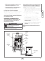
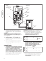
Main
Main Breaker Panel
Ground Bus
Neutral
Bus
To Generator
Neutral
Terminal
To Utility Meter
Supervisory
Contacts
Load
Connection
Ground Terminal
Generator
Connection
Utility
Connection
Current
Transformers
Model TS100A, TS100AD

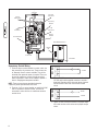
Supervisory Control Wiring
1. Terminal strip on control module in transfer switch has
four connections for customer use. There are two sets
of “Normally Closed” contacts available. They will be
activated when generator power is required. These can
be used for supervisory control of large connected
loads on generator. Loads will be allowed to operate if
there is enough generator power available.
NOTE: There are two wireways provided to keep the
supervisory loads separated from each other.
2. Terminals “A-A” on control module are rated for 24 VAC
and air conditioner contactor control. Contacts are
connected in series with the air conditioner contactor
control circuit.
3. Terminals “B-B” on control module are rated for 1 Amp
125 VAC and installer supplied contactor to control a
large load. Example: electric hot water heater. Contacts
are connected in series with the contactor control
circuit.
4. Tighten all wire connections/fasteners to proper torque.
See inside transfer switch enclosure for proper torque
values.
6
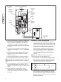
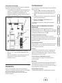
A
A
Air Conditioner Contactor
24 VAC
B
B
Contactor
Neutral
120 VAC
Main
Main Distribution Panel
Ground Bus
Neutral
Bus
To Generator
Neutral
Terminal
To Utility Meter
Supervisory
Contacts
Load
Connection
Ground Terminal
Generator
Connection
Current
Transformers
Model TS200A, TS200AD
Utility
Connection

7
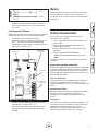
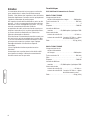
System Setup
You must perform the following before operating the system:
• If generator is installed in an area regularly subjected to
temperatures below 40°F (4°C), select a 50 second
warm up time by moving jumper installed on JP2 from
‘20’ position to ‘50’ position.
• Place the 2 position sliding switch on the control
module in the NG or LP position, whichever is
appropriate for your system.
• Place the 3 position sliding switch on the control
module to match the KW rating of the Home Standby
Generator set.
Controls
Other than a Manual Override lever, there are no operator
controls because this is an automatic transfer switch. The
manual override is to be used only by licensed professionals.
Operation
To select automatic transfer operation, do the following:
1. Set utility service disconnect circuit breaker in transfer
switch to “On” position.
2. Set generator disconnect circuit breaker in transfer
switch to “On” position.
3. Set generator’s main circuit breaker to its “On” position.
4. Install 15 Amp fuse in control panel on generator.
5A. If generator is equipped with a system ON/OFF switch,
set switch to “ON” position.
B. If generator is equipped with a AUTO/OFF/MANUAL
switch, set switch to “AUTO” position.
The system will now be in automatic operation mode.
When the generator is providing power to the transfer
switch, the controller is constantly monitoring generator
power. If the air conditioner is called to run, and there is
sufficient generator power available, the controller will close
contacts “A-A” to air conditioner contactor. Contacts “B-B”
will open before contacts A-A close. If loads are too great for
generator, contacts A-A and/or B-B will open. When air
conditioning is not needed, A-A will open. If enough power is
available, B-B will close.
Testing the Automatic Transfer Switch
Turn the utility disconnect circuit breaker in the transfer
switch, to the “Off” position. The automatic sequence will
follow. To go back to utility power, turn the utility disconnect
circuit breaker to the “On” position.
Utility Fail
The Home Standby Generator set senses when utility voltage
is below 70 percent of nominal. Engine start sequence is
initiated after 6 second time delay.
Engine Warm-Up
Time delay to allow for engine warm-up before transfer is
fixed at 20 seconds or 50 seconds with removal of jumper
on control board.
Transfer
Transfer from utility to generator supply occurs after voltage
is above set levels. Minimum engine run time is 5 minutes
after transfer.
Utility Pickup
Voltage pickup level is 80 percent of nominal voltage.
Retransfer
Retransfer from generator to utility supply is approximately
10 seconds after utility voltage supply is above pickup level
and minimum run time is completed.
Engine Cool Down
Engine will run for 60 seconds after retransfer.
2 Position
Switch
JP2
3 Position
Switch
CT1 & CT2
Connectors
Supervisory
Contacts

8
Maintenance
The transfer switch is designed to be maintenance free under
normal usage. However, inspection and maintenance checks
should be made on a regular basis. Maintenance will consist
mainly of keeping the transfer switch clean.
Visual inspections should be done at least once a month.
Access to transfer switch must not be obstructed. Keep
3 feet (92 cm) clearance around transfer switch. Check for
an accumulation of dirt, moisture and/or corrosion on and
around the enclosure, loose parts/hardware, cracks and/or
discoloration to insulation, and damaged or discolored
components.
Exercise the transfer switch at least once every three months
as described in the previous section Testing the Automatic
Transfer Switch unless a power outage occurs and Home
Generator System has gone through automatic sequence.
Allow generator to run for at least 30 minutes.
Contact a licensed electrical professional to inspect and clean
the inside of your transfer switch at least once a year.
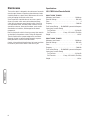
Specifications
UL® 1008 Listed Transfer Switch
Model TS100A, TS100AD
Maximum Load Current: . . . . . . . . . . . . . . . . . . . .100 Amps
Rated AC Voltage . . . . . . . . . . . . . . . . . . . . . . . . . .250 Volts
Poles . . . . . . . . . . . . . . . . . . . . . . . . . . . . . . . . . . . . . . . . . .2
Frequency . . . . . . . . . . . . . . . . . . . . . . . . . . . . . . . .50/60 Hz
Fault Current Rating . . . .22,000 RMS Symmetrical Amperes
Supervisory Contacts Rating:
A-A Terminals . . . . . . . . . . . . . . . . . . . . . . . . . .24 Volt AC
B-B Terminals . . . . . . . . . .1 Amp, 125 Volt AC, Pilot Duty
Weight . . . . . . . . . . . . . . . . . . . . . . . . . . . . . . . . . . . .32 lbs.
Model TS200A, TS200AD
Maximum Load Current: . . . . . . . . . . . . . . . . . . . .200 Amps
Rated AC Voltage . . . . . . . . . . . . . . . . . . . . . . . . . .250 Volts
Poles . . . . . . . . . . . . . . . . . . . . . . . . . . . . . . . . . . . . . . . . . .2
Frequency . . . . . . . . . . . . . . . . . . . . . . . . . . . . . . . .50/60 Hz
Fault Current Rating . . . .25,000 RMS Symmetrical Amperes
Supervisory Contacts Rating:
A-A Terminals . . . . . . . . . . . . . . . . . . . . . . . . . .24 Volt AC
B-B Terminals . . . . . . . . . .1 Amp, 125 Volt AC, Pilot Duty
Weight . . . . . . . . . . . . . . . . . . . . . . . . . . . . . . . . . . . .44 lbs.

9
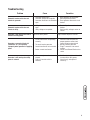
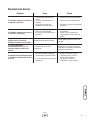
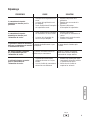
Troubleshooting
Problem Cause Correction
Automatic transfer switch does not
transfer to generator
1. Generator breaker open.
2. Generator voltage not acceptable.
3. Generator disconnect circuit breaker
open.
1. Reset generator circuit breaker.
2. Refer to generator manual.
3. Reset generator disconnect circuit
breaker.
Automatic transfer switch does not
transfer to utility
1. Utility disconnect circuit breaker
open.
2. Utility voltage not acceptable.
1. Reset utility disconnect circuit
breaker.
2. Wait for utility voltage to return to
normal.
Generator is still running after switch
transfers to utility power
Engine cool down period. Engine should stop after 1 minute.
Generator or supervised loads (air
conditioner, etc.) are operating
improperly when generator is supplying
power
1. A-A or B-B contacts not operating
correctly.
2. Too much load on generator.
3. Current transformer not connected.
4. Broken current transformer.
1. Check A-A or B-B contacts for
proper operation and/or check
control wiring to external load.
2. Decrease load to generator.
3. Plug CT connectors into control
module.
4. Contact local Rheem/Ruud service
center.
Generator is still running after utility
power is restored
1. Minimum engine run time has not
elapsed.
2. Fuse(s) in transfer switch is
defective.
1. Wait five minutes for transfer switch
to retransfer to utility power.
2. Check fuse(s) and replace if
necessary.

10
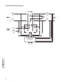
Transfer Switch Schematic Diagram

11
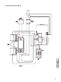
Transfer Switch Wiring Diagram

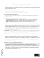
Warranty
12
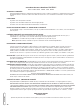
PROTECH™ Residential Standby Generators
Models: GEN12S GEN15S GEN20B GEN25B GEN30B
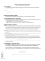
SCOPE of WARRANTY:
· This Limited Warranty provides that a replacement will be furnished for any part of the product which fails in normal use and service during the
Applicable Warranty Period specified, in accordance with the warranty’s terms. The replacement part is warranted for only the unexpired portion of the
original Applicable Warranty Period.
EXCEPTIONS:
· Commercial applications are not covered.
· Units installed as prime power source are not covered.
· Installations for the purpose of life support situations are not covered.
EFFECTIVE DATE of WARRANTY COVERAGE:
The Effective Date is the date of installation if properly documented; otherwise it is the date of manufacture plus six (6) months.
APPLICABLE WARRANTY PERIODS for VARIOUS PARTS:
All Residential Standby Generator Parts are warranted for an Applicable Warranty Period of Four (4) YEARS or 1500 operating hours, whichever occurs
first, after the Effective Date, except for the following specified product parts.
Transfer Switches - Transfer Switches (TS-100 and TS-200) carry a 3 year warranty for all parts.
Engine - The Briggs & Stratton engine warranty is covered by the manufacturer. Refer to Vanguard manual MS-3235
STANDARD PROVISIONS and CONDITIONS:
EXCLUSIONS - THIS WARRANTY WILL NOT APPLY: a) to damages, malfunctions or failures resulting from failure to properly install, operate or maintain the
unit in accordance with the manufacturer’s instructions provided; b) to damages, malfunctions or failures resulting from abuse, accident, fire, flood and
the like; c) to parts used in connection with normal maintenance, such as adjustments, fuel system cleaning and obstruction due to chemical, dirt,
carbon, lime and so forth; d) to units which are not installed in the United States of America or Canada; e) to units which are not installed in accordance
with applicable local codes, ordinances and good trade practices; f) to damages, malfunctions or failures caused by the use of any attachment,
accessory or component not authorized by the manufacturer; g) to wear items such as oil gauges, o-rings, filters fuses, or spark plugs etc.
SHIPPING COSTS: This Warranty does NOT cover shipping costs. You will be responsible for the cost of shipping warranty replacement parts from our factory
to our distributor and from the distributor to the location of your product. You also are responsible for any shipping cost of returning the failed part to
the distributor.
SERVICE LABOR RESPONSIBILITY: This Warranty does NOT cover any labor expenses for service, NOR for removing or reinstalling parts. All such expenses
are your responsibility, unless a service labor agreement exists between you and your contractor.
HOW TO OBTAIN WARRANTY PERFORMANCE: You must promptly report any failure covered by this warranty to the installing contractor or distributor.
Normally, the installing contractor from whom the unit was purchased will be able to take the necessary corrective action by obtaining through his
distributor any replacement parts. If the contractor is not available, simply contact any other local contractor handling RHEEM, RUUD or PROTECH air
conditioning products. The name and location of a local contractor can usually be found in your telephone directory or by contacting a RHEEM, RUUD
or PROTECH air conditioning distributor. If necessary, the following office can advise you of the nearest distributor:
4744 Island Ford Road, Randleman, NC 27317
HOWEVER, ANY REPLACEMENTS ARE MADE SUBJECT TO VALIDATION OF IN-WARRANTY COVERAGE. An item to be replaced must be made available
in exchange for the replacement.
EXCLUSIVE WARRANTY - LIMITATION OF LIABILITY:
This Limited Warranty is the ONLY warranty for the unit given by the manufacturer. No one is authorized to make any warranties on their behalf. ANY
IMPLIED WARRANTIES, INCLUDING MERCHANTABILITY OR FITNESS FOR A PARTICULAR PURPOSE, SHALL NOT EXTEND BEYOND THE
APPLICABLE WARRANTY PERIODS SPECIFIED ABOVE. RHEEM’S SOLE LIABILITY WITH RESPECT TO DEFECTIVE PARTS OR FAILURES SHALL BE AS
SET FORTH IN THIS LIMITED WARRANTY, AND ANY CLAIMS FOR INCIDENTAL OR CONSEQUENTIAL DAMAGES ARE EXPRESSLY EXCLUDED. Some
states do not allow limitations on how long an implied warranty lasts, or for the exclusion of incidental or consequential damages, so the above
limitation or exclusion may not apply to you. This Limited Warranty gives you specific legal rights, and you may also have other rights which vary from
state to state.
202249E, Rev. -, 1/3/2007
RHEEM SALES COMPANY
Randleman NC
“In the spirit of continuous improvement, we reserve the right to make changes without notice.”

100 Amp / 200 Amp
Conectador Automático
y Disyuntor Seccionador
Bipolar de la red Pública
MMaannuuaall ddee IInnssttaallaacciióónn yy ddeell OOppeerraarriioo
TS100A, TS100AD and TS200A, TS200AD
Preguntas?
La ayuda es justa un momento lejos!
Llamada: Línea Directa de Conectador Automático
(877) 369-9400 M-F 8-5 CT

Gracias por comprar este conectador automático Rheem and Ruud. Este producto SÓLO es adecuado para utilización con
grupos electrógenos domésticos de reserva de Rheem/Ruud. Este producto es un sistema doméstico de reserva opcional y
proporciona una fuente alternativa de energía eléctrica con capacidad para alimentar cargas tales como calderas de gas y
sistemas de refrigeración y de telecomunicaciones, que cuando dejan de funcionar a causa de una interrupción de la
alimentación eléctrica de la red pueden producir incomodidades o problemas. Este producto no pertenece a la categoría de
reserva de emergencia según lo definido por la norma NFPA 70 (NEC).
Este manual contiene información de seguridad sobre los riesgos asociados con los conectadores y sobre cómo evitarlos.
Rheem/Ruud ha realizado el máximo esfuerzo para que la instalación resulte segura, sencilla y económica. Cada instalación es
única, lo que hace imposible conocer y recomendar todos los procedimientos y métodos posibles para efectuarla. No
conocemos todos los riesgos y/o resultados posibles de cada método o procedimiento. Guarde estas instrucciones para
futuras consultas.
Antes de utilizar el conectador, es necesario instalarlo. Consulte en la sección Instalación de este manual las instrucciones
o procedimientos de instalación. Los conectadores sólo deben ser instalados por electricistas cualificados. Las
instalaciones deben cumplir estrictamente la totalidad de la normativa vigente.
Dónde puede encontrarnos
Nunca tendrá que buscar mucho para poder obtener soporte y servicio técnico para su conectador Rheem/Ruud. Consulte las
páginas amarillas. Hay muchos distribuidores de servicio autorizados de Rheem and Ruud que ofrecen servicio de calidad.
También puede dirigirse al departamento de servicio al cliente de Rheem llamando al (877) 369-9400.
Conectador Automático
Número de Modelo
Revisión
Número de Serie
Fecha de compra
Rheem Sales Company
Randleman, NC 27317
(877) 369-9400
Copyright © 2007 Rheem Sales Company. Reservados todos los
derechos. Queda prohibida la reproducción o transmisión total o
parcial de este material, sea cual sea la forma y el medio
empleados para ello, sin el permiso previo y por escrito de Rheem
Sales Company.

1
Español
11
Instrucciones Importantes de Seguridad . . . . . . . . . . . . . . . . . . . . . . . . . 2
Orientación para el Propietario . . . . . . . . . . . . . . . . . . . . . . . . . . . . . . . . . . 3
Responsabilidades del Instalador . . . . . . . . . . . . . . . . . . . . . . . . . . . . . . . . 3
Descripción del Equipo . . . . . . . . . . . . . . . . . . . . . . . . . . . . . . . . . . . . . . . . 3
Instalación . . . . . . . . . . . . . . . . . . . . . . . . . . . . . . . . . . . . . . . . . . . . . 4
Desempaque . . . . . . . . . . . . . . . . . . . . . . . . . . . . . . . . . . . . . . . . . . . . . . . . 4
Pautas de Montaje . . . . . . . . . . . . . . . . . . . . . . . . . . . . . . . . . . . . . . . . . . . . 4
Interconexiones de Cableado de Energía . . . . . . . . . . . . . . . . . . . . . . . . . . . 5
Cableado de Control de Supervisión . . . . . . . . . . . . . . . . . . . . . . . . . . . . . . 6
Configuración del Sistema. . . . . . . . . . . . . . . . . . . . . . . . . . . . . . . . . . . . . . 7
Mandos. . . . . . . . . . . . . . . . . . . . . . . . . . . . . . . . . . . . . . . . . . . . . . . . 7
Sistema Funcionamiento . . . . . . . . . . . . . . . . . . . . . . . . . . . . . . . . . . . . 7
Prueba del conectador automático . . . . . . . . . . . . . . . . . . . . . . . . . . . . . . . 7
Mantenimiento. . . . . . . . . . . . . . . . . . . . . . . . . . . . . . . . . . . . . . . . . . . 8
Especificaciones. . . . . . . . . . . . . . . . . . . . . . . . . . . . . . . . . . . . . . . . . . . . . . 8
Reparacion De Averias . . . . . . . . . . . . . . . . . . . . . . . . . . . . . . . . . . . . . 9
Garantia . . . . . . . . . . . . . . . . . . . . . . . . . . . . . . . . . . . . . . . . . . . . . . 10
Tabla de Contendio

2
Instrucciones Importantes de
Seguridad
Éste es el símbolo de alerta de seguridad. Sirve
para advertir al usuario de un posible riesgo para
su integridad física. Siga todos los mensajes de
seguridad que figuren después de este símbolo
para evitar lesiones o incluso la muerte.
El símbolo de alerta de seguridad ( ) se utiliza con una
palabra de señalización (PELIGRO, PRECAUCIÓN,
ADVERTENCIA), una imagen y/o un mensaje de seguridad
para advertir al usuario de un riesgo. PELIGRO indica un
riesgo que, de no evitarse, provocará la muerte o lesiones de
gravedad. ADVERTENCIA indica un riesgo que, de no
evitarse, puede provocar la muerte o lesiones de gravedad.
PRECAUCIÓN indica un riesgo que, de no evitarse, puede
provocar lesiones moderadas. Cuando se utiliza sin el
símbolo de alerta, AVISO indica una situación que podría
producir daños en el equipo. Siga en todo momento los
mensajes de seguridad para evitar o reducir el riesgo de
lesiones y de muerte.
El fabricante no puede prever todas las posibles
circunstancias que pueden implicar riesgos. Por lo tanto, las
advertencias que aparecen en este manual y las etiquetas y
calcomanías adheridas a la unidad no incluyen todas las
posibilidades. Si aplica un procedimiento, método de trabajo
o técnica de operación no recomendada específicamente por
el fabricante, debe estar seguro de que se trata de una
práctica segura para usted y para otras personas. También
debe asegurarse de que el procedimiento, método de trabajo
o técnica de operación que elija, no haga que el conmutador
de transferencia se torne inseguro.
Conserve estas instrucciones
ADVERTENCIA
Únicamente los electricistas capacitados pueden intentar
instalar este sistema. Dicha instalación debe cumplir
estrictamente con los códigos, las regulaciones y las
normas correspondientes.
• Si no se respeta esta indicación pueden producirse lesiones,
daños y/o fallos de funcionamiento del equipo.
ADVERTENCIA
Los cables de baja tensión no se pueden instalar
en el mismo conducto que los cables de
suministro de energía.
• No toque los alambres pelados o receptáculos.
• No use un conmutador de transferencia con cables eléctricos
que estén malgastados, rotos, pelados o dañados de cualquier
forma.
• No maneje el cables eléctricos mientras esté parado en agua,
descalzo o cuando las manos y los pies estén mojados.
• Si fuera necesario realizar trabajos en cercanías de la unidad
mientras está en funcionamiento, párese sobre una superficie
seca y aislada para reducir los riesgos de una descarga.
• No permita que personas descalificadas o niños operen o sirvan
al conmutador de transferencia.
• En caso de que se produzca un accidente causado por una
descarga eléctrica, cierre inmediatamente la fuente de energía
eléctrica y contacta administración local. Evite el contacto
directo con la víctima.
ADVERTENCIA
Si no hace tierra apropiadamente con un sistema
de gestión de energía eléctrica, puede hacer que
ocurra un electrocutamiento.
• A pesar del diseño seguro del conmutador de transferencia, si se
opera este equipo en forma imprudente, si no se cumple con el
mantenimiento o si se actúa con descuido, se pueden producir
lesiones o la muerte.
ADVERTENCIA
El conmutador de transferencia contiene alta
tensión que puede provocar lesiones o la muerte.
• Use el conmutador de transferencia solamente con la finalidad
para el cual fue diseñado.
• En caso de dudas sobre su uso, diríjase al distribuidor o a
Rheem Sales Company.
• No exponga al conmutador de transferencia a una humedad
excesiva, polvo, suciedad o vapores corrosivos.
• Permanezca siempre alerta cuando trabaje con este equipo.
NUNCA trabaje con este equipo si se siente cansado física o
mentalmente.
• Si se calientan excesivamente los dispositivos conectados,
apáguelos y abra sus interruptores o quite sus fusibles.
AVISO
El tratamiento inadecuado del conmutador de transferencia
eléctrica puede dañarlo y acortar su vida productiva.

3
Español
Introducción
Su conectador se suministra con este "Manual de Instalación
y del Operario" combinado. Se trata de un documento
importante que debe ser conservado por el propietario
después de haber terminado la instalación.
Se han tomado todos los recaudos posibles para asegurar
que la información incluida en este manual sea correcta y
esté actualizada. Sin embargo, los fabricantes se reservan el
derecho de cambiar, alterar o mejorar el sistema de cualquier
otra manera y en cualquier momento, sin previo aviso.
Para el Propietario Doméstico
Para que pueda tomar decisiones fundamentadas y lograr
una comunicación efectiva con el o los contratistas de
instalación,
Lea y comprenda la sección de este manual denominada
Orientación para el Propietario ANTES de contratar o
iniciar la instalación de su conmutador de transferencia.
Para coordinar y organizar una instalación adecuada,
consulte al comercio en el cual adquirió su conmutador de
transferencia Rheem and Ruud, a su agente de ventas o a la
compañía proveedora de electricidad.
La garantía del conmutador de transferencia se ANULA si
la instalación del sistema no está a cargo de
profesionales especializados en electricidad certificados.
Orientación para el Propietario
Las ilustraciones se aplican a circunstancias típicas y están
destinadas a que usted se familiarice con las opciones de
instalación disponibles con su conmutador de transferencia.
Los códigos locales, la apariencia y las distancias son los
factores fundamentales a tener en cuenta cuando se realiza
la negociación con el profesional que tendrá a su cargo la
instalación. Recuerde que a medida que la distancia del
servicio de electricidad existente aumenta, se debe tener en
cuenta una compensación igual en los materiales de
cableado. Esto es necesario para cumplir con los códigos
locales y solucionar caídas en la tensión eléctrica.
Los factores antes mencionados tendrán un efecto directo
sobre el precio general de la instalación del conmutador
de transferencia.
NOTA: El instalador debe verificar los códigos locales Y
obtener los permisos correspondientes antes de instalar el
sistema.
• Lea y cumpla las instrucciones incluidas en el manual.
• Siga un programa regular para cuidar y utilizar el
conmutador de transferencia, según se especifica en el
manual.
Responsabilidades del Instalador
• Lea y observe las reglas de seguridad que se
encuentran en el manual.
• Lea y siga las instrucciones que se encuentran en este
manual.
• Consulte toda la normativa nacional y local.
• Asegúrese de que las cargas seleccionadas no
sobrecargan el generador.
Si necesita más información sobre el conectador, llame al
(877) 369-9400, de 08:00 a 17:00 CT.
Descripción del Equipo
Estos conectadores pertenecen a una nueva generación
destinada a transferir toda la carga de instalaciones
residenciales normales cuando se utilizan con los contactos
de supervisión previstos. La carga se conecta a la red
pública (normal) o a la alimentación doméstica de reserva
(generador). El conectador monitoriza las tensiones de la red
pública y del generador y conecta automáticamente la carga
a la fuente de alimentación apropiada.
Con estos interruptores, un electricista cualificado puede
completar fácilmente una instalación doméstica de reserva.
La unidad contiene un seccionador de servicio y un
conectador automático en una misma caja. El conducto y los
conductores de servicio se pueden cablear directamente
desde el contador hasta el conectador. No es necesario
instalar un seccionador distinto, con su correspondiente
cableado, para cumplir toda la normativa vigente.
Los componentes principales del conectador son un
disyuntor seccionador de servicio bipolar, un interruptor
bipolar de 2 posiciones de contacto, una tarjeta de circuito
impreso del módulo de control, terminales con fusibles de
detección de tensión de la red pública y cableado de
interconexión.
El conectador es accionado por un solenoide alimentado
desde las entradas de la red pública o del generador y tiene
interruptores de enclavamiento mecánicos y eléctricos,
adecuados para eliminar la posibilidad de conectar la red
pública a la salida del generador. Sus valores nominales son
suficientes para conectar toda potencia de la red pública a la
residencia. Para la función de transferencia hay una palanca
de cancelación manual.
La tarjeta de circuito impreso del módulo de control tiene
circuitos activos que detectan las tensiones de la red pública
y del generador. Genera una señal para el arranque del
generador, el conectador, la retransferencia cuando se
restablece la tensión en la red pública y los períodos de
enfriamiento del generador. La tarjeta de control contiene
también luces rojas y verdes que indican las fuentes de
alimentación disponibles y dos contactos accionados por
relé que proporcionan el control de supervisión de cargas
críticas externas.

4
Instalación
Desempaque
Inspección al Momento de la Entrega
Luego de retirar la caja, inspeccione cuidadosamente el los
componentes del conmutador de transferencia de energía
automático para detectar cualquier daño que pudiera haber
ocurrido durante el traslado.
IMPORTANTE: Si en el momento de la entrega se detecta
alguna pérdida o daño, solicite a la persona o personas
encargadas de la entrega que dejen debida constancia en la
nota de entrega y que firmen debajo de la nota del
consignador donde se informa acerca de la pérdida o daño.
Si la pérdida o el daño se detecta después de la entrega,
separe los materiales dañados y póngase en contacto con el
transportista para llevar a cabo los procedimientos de
reclamo. Las piezas perdidas o dañadas no están
garantizadas.
Contenido de la Caja
• Conmutador de transferencia de energía automático
• Manual de instalación y operario
Pautas de Montaje
El conectador automático está encerrado en una caja tipo 3R
NEMA, que es adecuada para uso en interiores y a la
intemperie. Las directrices para el montaje de conectador
automático incluyen:
• Instale el conmutador sobre una estructura de soporte
firme y resistente.
• El interruptor se debe instalar con conexiones mínimas
de conduit de fo de hardware de NEMA 3R.
• Para evitar distorsiones en el conmutador, nivele la
unidad si es necesario. Puede hacerlo colocando
arandelas entre el compartimiento del conmutador y la
superficie de montaje.
Típico
Alternativo
Panel del
Disyuntor
Principal
Conmutador de
Transferencia
w/Seccionador de
servicio
Calentador
de agua
Acondicionador
de aire
Contactor
Generador
Contador de
vatios hora
Circuitos derivados
— — — — — — Cableado de control
Seccionador
Panel del
Disyuntor
Principal
Conmutador
de
Transferencia
Calentador
de agua
Acondicionador
de aire
Contactor
Seccionador
Generador
Contador de
vatios hora
Circuitos derivados
de emergencia
Circuitos derivados
— — — — — — Cableado de control
Centro de
carga de
emergencia
La page est en cours de chargement...
La page est en cours de chargement...
La page est en cours de chargement...
La page est en cours de chargement...
La page est en cours de chargement...
La page est en cours de chargement...
La page est en cours de chargement...
La page est en cours de chargement...
La page est en cours de chargement...
La page est en cours de chargement...
La page est en cours de chargement...
La page est en cours de chargement...
La page est en cours de chargement...
La page est en cours de chargement...
La page est en cours de chargement...
La page est en cours de chargement...
La page est en cours de chargement...
La page est en cours de chargement...
La page est en cours de chargement...
La page est en cours de chargement...
-
 1
1
-
 2
2
-
 3
3
-
 4
4
-
 5
5
-
 6
6
-
 7
7
-
 8
8
-
 9
9
-
 10
10
-
 11
11
-
 12
12
-
 13
13
-
 14
14
-
 15
15
-
 16
16
-
 17
17
-
 18
18
-
 19
19
-
 20
20
-
 21
21
-
 22
22
-
 23
23
-
 24
24
-
 25
25
-
 26
26
-
 27
27
-
 28
28
-
 29
29
-
 30
30
-
 31
31
-
 32
32
-
 33
33
-
 34
34
-
 35
35
-
 36
36
-
 37
37
-
 38
38
-
 39
39
-
 40
40


Rheem 071028-0 Manuel utilisateur
- Catégorie
- Groupes électrogènes
- Taper
- Manuel utilisateur
dans d''autres langues
- English: Rheem 071028-0 User manual
- español: Rheem 071028-0 Manual de usuario
Documents connexes
Autres documents
-
Simplicity 071026-0 Manuel utilisateur
-
-
-
-
-