

Introduction 3
Safety warnings 4
Connectors, displays and mounting 5
Placing the transmitter 6
Installation 7
Extending the system 8
Troubleshooting 9
Technical data 10
Maintenance, care and disposal 11
Contents
2 English

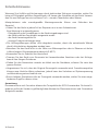
Congratulations on the purchase of the High-Power IR transmitter IR-TX4. You have chosen a
modern and reliable device.
It uses invisible infrared light for the transmission of either one stereo channel or two separate
mono channels of any audio source of your choice, for example TV sets, DVD-players, stereo-
sets, radios and microphones.
The IR-TX4 two-channel infrared transmitter combines infrared modulator and emitter tech-
nology into a single mountable enclosure - which reduces operating costs, eliminates the need
for rack space and eases set-up.
The 2.3/2.8 MHz operating frequencies minimize high-eiciency light-
ing interference.
The system is easy to install. As it does not use FM, the transmission stays within the room
in which the system has been installed. This characteristic is of interest for applications
demanding high levels of discretion, for example in courts of law.
The system can be used in laboratories, hospitals, churches, classrooms, theatres and cinemas.
Extending the transmission area is easy, it is possible to link up any amount of further IR-TX4
transmitters.
No FCC license or radio approval is required with this equipment. It can be used anywhere in
the world.
Receivers are needed (e. g. IR-RXU, IR-RX2) to transform the infrared signal back into audible
sound.
Characteristics:
- Input Auto-Level Control (ALC) Range: 250 mV to 6V
- Eective area covered: 900 m² (in closed rooms)
- For wall mounting or tripod use
- Synchro-signal interface for easy expansion
- Optional dual channell
Introduction
English 3
EN

Warning! To reduce the risk of re or electric shock, do not expose the system to rain or mois-
ture. Do not use this apparatus near water. The system should not be exposed to dripping or
splashing, and objects lled with liquids such as beverages should not be placed on the trans-
mitter or receivers. Clean only with a dry cloth.
Servicing or attempting to service this device will void the warranty
• Refer servicing to qualied personnel. Servicing is required when the system has been
damaged in any way: if liquid has been spilled or objects have fallen into the unit, if the unit
has been exposed to moisture, if the unit does not operate normally, or if the unit has been
dropped.
• Do not block any ventilation openings. Install in accordance with manufacturer’s instruc-
tions.
• Do not install near any heat sources such as radiators, heat registers, stoves, or other
apparatus that produces heat.
• Use only attachments/accessories specied by the manufacturer.
• Unplug the transmitter during lightning storms or when unused for long periods of time.
• Be advised that dierent operating voltages require the use of dierent types of line cord
and attachment plugs. Check the voltage in your area and use the correct type.
• Use only the power supply provided by Contacta. Other power supplies may have
similar specications, but may not be equivalent in emissions ratings, in-rush current, etc.
• Use of an unapproved power supply may leave the device partially or completely inoper-
able, and will void the warranty.
• Protect the power cord from being walked on or pinched, particularly at plugs, receptacles,
and near the power jack on the transmitter.
• The Mains plug or an appliance coupler is used as the disconnect device, so the disconnect
device should remain readily operable.
NOTE:
A plasma monitor or television can degrade the audio quality of the IR-TX4 transmitter. For
best performance, the transmitter should be positioned as far away as possible from any plas-
ma monitor or television.
Safety Warnings
4 English

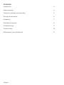
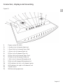
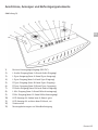
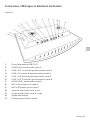
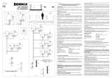
Figure A)
1) Power socket DC (28V)
2) L Audio-In (or A-channel Audio-In)
3) L Sync-Out (or A-channel Sync-Out)
4) L Sync-In (or A-channel Sync-In)
5) R Sync-In (or B-channel Sync-In)
6) R Sync-Out (or B-channel Sync-Out)
7) R Audio-In (or B-channel Audio-In)
8) L Mic-In (or A-channel Microphone-In)
9) R Mic-In (or B-channel Microphone-In)
10) LED-indicator for left- or A-channel, green
11) LED-indicator for right- or B-channel, red
12) Tripod mount
13) Wall mounting apertures
Connectors, displays and mounting
English 5
EN

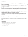
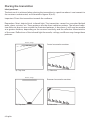
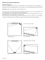
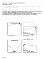
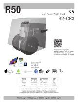
Ideal positions
The best result is achieved when placing the transmitter in a position where it can transmit to
the receivers unobstructed, as illustrated in gures B) to E).
Important: Direct the transmitter towards the audience.
Remember: Most objects block infrared light. The transmitter cannot be concealed behind
walls, glass, curtains, etc. These patterns are the direct radiation pattern. The infrared radia-
tion does not drop to zero outside the illustrated patterns; it decreases. It still may be useable
at a greater distance, depending on the receiver sensitivity and the reective characteristics
of the room. Reections of the infrared light from walls, ceilings, and oors may change these
patterns.
Placing the transmitter
Screen / stage
Frontal mounted transmitter
Rearward mounted transmitter
Screen / stage
B) Top view
D) Top view E) Side view
C) Side view
6 English

Installation
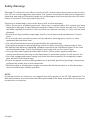
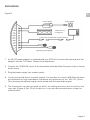
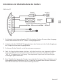
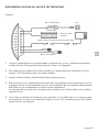
Figure F)
1. An AC/DC power adaptor is supplied with your IR-TX4. First insert the output jack of the
adaptor into the “DC Power“ socket of the transmitter.
2. Connect the ”AUDIO IN” ports of the transmitter with the Audio-Out ports of your chosen
audio source.
3. Plug the power supply into a mains outlet.
4. In case you would like to transmit speech, it is possible to connect 600 Ohm dynamic
microphones (or high impedance condenser microphones) to the “MIC-IN”- ports.
The incoming microphone signal can be mixed with the main audio signal.
5. The transmitter can be mounted on walls, according apertures are located on the
rear side (Figure A, Pos. 13) of the device. It can also be mounted upon a tripod or
other bracket.
Power supply Mains outlet
audio sources,
as required
Connection to Audio-Out of audio sources
Optionally: Microphones
English 7
EN

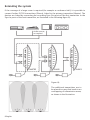
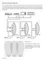
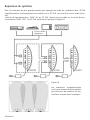
Extending the system
If the coverage of a larger room is required (for example a conference hall), it is possible to
connect further IR-TX4 transmitters (Slaves), linked to the primary transmitter (Master). The
devices are linked by connecting the according Sync-Out-ports of the rst transmitter to the
Sync-In-ports of the next transmitter, as illustrated in the following gure G):
Figure H):
The additional transmitters are to
be placed in a way that leads to an
overlapping of transmission areas,
as shown in the illustration.
Audio sources,
as required
8 English

Should you have problems with your infrared system, please check the following points before
requesting service.
No infrared emission:
- Make sure the power adaptor is connected to a mains outlet.
- Make sure that the mains outlet is supplied with electricity (check external switches etc.)
Input indicator LED does not light up:
- Make sure the IR-TX4 is plugged in properly
- Check if the Audio-In is connected to the Audio-Out of the source.
- Verify that a suicient audio signal is sent to the IR-TX4.
No sound produced by the receivers:
- Make sure the receivers are set to the frequency of the transmitter.
- Should some receivers work but others not, it is adviseable to check the batteries of the
receivers.
- If no receiver is working, please check if the input indicator LEDs are on.
- Check to see if the transmitter is connected properly to the audio source. The audio-level
indicators should ash on channels that have audio.
- Make certain the transmitter is not covered by objects which would block infrared light.
Sound reproduction of receivers is low and interferred:
- Try to adjust the Audio-In level. Should the sound be in order, then it may be necessary to
reposition the transmitter or add a further IR-TX4 to the system.
Poor sound quality, distorsions:
- Check for ground loops or noise on the input signal.
- Check the input signal for overload.
- Distance between transmitters and receivers is out of optimum.
Interruptions in transmission:
- Distance between transmitters and receivers is out of optimum.
- Inappropriate position of transmitter (Consider relocating the transmitter or receivers, avoid
obstructions in the line of sight between transmitter and receivers).
If these instructions do not address your problem or the issue persists, please call
your authorized dealer or representative.
Troubleshooting
English 9
EN

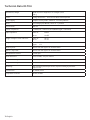
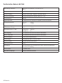
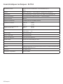
Technical Data IR-TX4
Dimensions, weight Width 41,2 cm x height 32,7 cm x length 7,5 cm
1100 g
Colour Casing: Anthracite / Front screen: Dark red transparent
Power supply Adaptor: Primary 230V~ 50-60 Hz, secondary 28V DC
DC-In Low voltage jack, 28V DC, center is “+“ positive
Current drain 700 mA
Carrier frequencies 2,3 MHz (left / channel A) and 2,8 MHz (right / channel B)
Input impedance Audio-In: 18 KΩ
Mic-In: 1.3 KΩ
Trigger voltage of level indicators Audio-In: 110 mV
Mic-In: 1.5 mV
Range at +/- 3dB Lower: 400 mV
Upper: 6 V
Audio-In ports RCA for left and right or A- and B-channel
Sync-in / Sync-Out RCA for left and right or A- and B-channel
Microphone-In-socket 6,4 mm jack
Audio indicators Level-In-LEDs, one per channel
Transmission range 30 metres, indoors
Temperature range 0-40°C
Mounting: Wall mounting with simple hooks, tripod mounting by standard
tripod screw
Conformities CE, WEEE, RoHS
Compatible receivers IR-RXU, IR-RX2
10 English

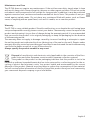
Maintenance and Care
The IR-TX4 does not require any maintenance. If the unit becomes dirty, simply wipe it clean
with a soft, damp cloth. Never use spirits, thinners or other organic solvents. Do not set up the
unit where it will be exposed to full sunlight for long periods. In addition it must be protected
against excessive heat, moisture and severe mechanical shock. Note: This product is not pro-
tected against splash water. Do not place any containers lled with water, such as ower
vases, or anything with an open ame, such as a lit candle, on or near the product.
Warranty
The IR-TX4 is a very reliable product. Should a malfunction occur despite the unit having been
set up and operated correctly, please contact your dealer. The warranty covers the repair of the
product and returning it to you free of charge during the warranty period. It is recommended
that you send in the product in its original packaging, so keep the packaging for the duration
of the warranty period.
The warranty does not apply to damage caused by incorrect handling or attempts to repair
the unit by people not authorised to do so (destruction of the seal on the unit). Repairs under
warranty are only carried out providing you have lled in and returned the enclosed warranty
card from the dealer as well as a copy of the sales slip.
Always specify the product number in any event.
Disposal of used electric and electronic units (applicable in the countries of the Euro-
pean Union and other European countries with a separate collection system).
The symbol on the product or the packaging indicates that this product is not to be
handled as ordinary household waste but has to be returned to a collecting point for the re-
cycling of electric and electronic units. You protect health and environment by the correct
disposal of this product. Material recycling helps to reduce the consumption of raw material.
You will receive further information on the recycling of this product from your local community,
your communal disposal company or your local dealer.
English 11
EN

Einleitung 13
Sicherheitshinweise 14
Anschlüsse, Anzeigen und Befestigungselemente 15
Wahl des Senderstandortes 16
Installation und Inbetriebnahme 17
Erweiterung des Systems 18
Fehlerbehebung 19
Technische Daten 20
Wartung, Pege, Entsorgung 21
Inhalt
12 Deutsch

Wir beglückwünschen Sie zum Erwerb Ihres Hochleistungs-Infrarotsenders IR-TX4. Sie haben
sich dabei für ein modernes und zuverlässiges Gerät entschieden.
Es verwendet unsichtbares Infrarotlicht zur Übertragung von entweder einem Stereokanal
oder zwei getrennten Monokanälen einer beliebigen Tonquelle, wie zum Beispiel Fernseher,
DVD-Player, Stereoanlagen, Radios und Mikrofone.
Der IR-TX4 Zweikanal-Infrarotsender vereint Modulator und Infrarot-Sendertechnologie zu ei-
nem einzigen, einfach zu montierendem Gerät. Dies spart Zeit und Betriebskosten, es benötigt
keinen Platz in Audio-Racks. Die Arbeitsfrequenz von 2,3 / 2,8 MHz minimiert Störungseinüs-
se durch Beleuchtungseinrichtungen.
Das System ist einfach zu installieren. Da keine Funkwellen verwendet werden, bleibt die
Übertragung in dem Raum, in welchem das System in Betrieb ist. Diese Eigenschaft ist bei
Anwendungen mit hohem Diskretionsbedarf von Vorteil, wie zum Beispiel in Gerichtssälen.
Das System kann in Laboratorien, Krankenhäusern, Kirchen, Klassenzimmern, Theatern und
Kinos verwendet werden.
Eine Erweiterung der Sendeäche ist durch den Anschluss einer beliebigen Anzahl weiterer
IR-TX4 Sender problemlos möglich.
Es werden keinerlei FCC- Post- oder Funkgenehmigungen benötigt. Das Gerät kann weltweit
verwendet werden.
Es werden zusätzlich entsprechende Empfangsgeräte (zum Beispiel IR-RXU, IR-RX2) zur Rück-
wandlung des Infrarotsignals in hörbaren Ton benötigt.
Merkmale:
- Automatische Eingangspegelkontrolle ( ALC ) Bereich: 250 mV bis 6V
- Eektive Fläche pro Sender: 900 m² (in geschlossenen Räumen)
- Für Wandmontage oder Stativ
- Synchro-Signalschnittstellen zur einfachen Erweiterung
- Zwei Kanäle zur Auswahl
Einleitung
Deutsch 13
DE

Warnung! Um Unfälle und Verletzungen durch elektrischen Schlag zu vermeiden, stellen Sie
keine mit Flüssigkeit gefüllten Gegenstände, z.B. Vasen oder Getränke auf das Gerät. Verwen-
den Sie zum Reinigen nur ein trockenes Tuch – niemals Chemikalien oder Wasser.
Manipulationen oder unsachgemäße Wartungsversuche führen zum Erlöschen der
Garantie!
• Geben Sie das Gerät in jedem Fall zur Reparatur nur in eine Fachwerkstatt.
Eine Wartung ist notwendig wenn:
- Flüssigkeiten oder Fremdkörper in das Gerät eingedrungen sind
- das Gerät erhöhter Feuchtigkeit ausgesetzt wurde
- das Gerät heruntergefallen ist
- sonstige Funktionsstörungen zeigt.
• Die Lüftungsönungen dürfen nicht abgedeckt werden, damit die entstehende Wärme
durch Luftzirkulation abgegeben werden kann.
• Betreiben Sie das Gerät nicht in der Nähe von Wärmequellen oder in Räumen mit hoher
Luftfeuchtigkeit. (Einsatztemperaturbereich 0-40°C)
• Verwenden Sie nur Zubehör des Herstellers!
• Trennen Sie das Gerät vom Stromnetz bei heranziehenden Gewittern oder bei Nichtge-
brauch über längere Zeiträume.
• Ziehen Sie den Netzstecker niemals am Kabel aus der Steckdose, erfassen Sie stets den
ganzen Stecker.
• Vergewissern Sie sich, dass die Original-Stromquelle verwendet wird. Fremdstromquellen
können zwar ähnliche Werte aufweisen, jedoch kann das Verhalten auf Spitzenspannung
und Abstrahlung unterschiedlich sein.
• Eine schaltbare Steckdose sollte als Trenngerät verwendet werden, stellen Sie einen unge-
hinderten Zugri zu dieser sicher.
Anmerkung:
Plasmamonitore und -Fernseher können die Tonqualität des IR-TX4 vermindern. Für beste Er-
gebnisse sollte der Sender in größtmöglichem Abstand zu Plasmamonitoren und -Fernsehern
aufgestellt werden.
Sicherheitshinweise
14 Deutsch

Abbildung A)
1) Buchse Versorgungseingang (28V DC)
2) L Audio-Eingang (bzw. A-Kanal Audio-Eingang)
3) L Sync-Ausgang (bzw. A-Kanal Sync-Ausgang)
4) L Sync-Eingang (bzw. A-Kanal Sync-Eingang)
5) R Sync-Eingang (bzw. B-Kanal Sync-Eingang)
6) R Sync-Ausgang (bzw. B-Kanal Sync-Ausgang)
7) R Audio-Eingang (bzw. B-Kanal Audio-Eingang)
8) L Mic Eingang (bzw. A-Kanal-Mikrofoneingang)
9) R Mic Eingang (bzw. B- Kanal-Mikrofoneingang)
10) LED-Anzeige für linken bzw. A-Kanal, grün
11) LED-Anzeige für rechten bzw. B-Kanal, rot
12) Stativsockel
13) Montagebohrungen zur Wandbefestigung
Anschlüsse, Anzeigen und Befestigungselemente
Deutsch 15
DE

Optimale Standorte
Das beste Ergebnis erzielt man mit einem Standort, von welchem der Sender die Signale un-
gehindert auf die Empfängergeräte aussenden kann, wie in den Abbildungen B) bis E) gezeigt.
Wichtig: Richten Sie den Sender auf das Publikum aus.
Zur Erinnerung: Die meisten Gegenstände behindern infrarotes Licht. Der Sender kann nicht
hinter Wänden, Glas, Vorhängen usw. verborgen werden.
Die dargestellten Linien deuten die direkt bestrahlte Fläche an. Die Abstrahlung fällt ausser-
halb dieser Bereiche nicht auf Null - sie nimmt ab.
Das Gerät kann ausserhalb dieser Fläche brauchbar sein, dies ist jedoch von der Empnd-
lichkeit der Empfänger und der Reektionseigenschaften der Räumlichkeit abhängig.
Wahl des Senderstandortes
Frontal montierter Sender
B) Obenansicht
D) Obenansicht
C) Seitenansicht
E) Seitenansicht
Rückwärtig montierter Sender
Leinwand / Bühne
Leinwand / Bühne
16 Deutsch

Installation und Inbetriebnahme des Senders
Abbildung F)
1. Ein Netzteil ist im Lieferumfang des IR-TX4 enthalten. Stecken Sie zuerst den Ausgangs-
stecker des Netzteils in die DC “Power“ Versorgungsbuchse.
2. Verbinden Sie die ”AUDIO IN” Eingangsbuchsen des Senders mit den Audio-Ausgängen
der Tonquelle mittels des Eingangskabels.
3. Schliessen Sie das Netzteil an die Hausstromversorgung an.
4. Falls Sie Sprache übertragen möchten, steht der Anschluss von dynamische Mikro-
fonen mit 600 Ohm (oder Kondensatormikrofone mit hoher Impedanz) an den
“MIC IN”-Eingängen zur Verfügung. Das eingehende Signal kann mit dem übrigen
Audiosignal gemischt werden.
5. Eine Wandbefestigung des Senders ist möglich. Zu diesem Zweck befinden sich
Montagebohrungen (Abbildung A, Pos. 13) auf der Rückseite des Gerätes. Alternativ
kann der Sender auch auf einem Stativ befestigt werden.
Netzteil Steckdose
Tonquellen,
beliebig
Anschluss an Audio-Ausgang der Tonquellen
Optional: Mikrofone
Deutsch 17
DE

Zur Versorgung größerer Räumlichkeiten (zum Beispiel ein Konferenzsaal) können zusätzliche
IR-TX4 Sender (Slaves) an den ersten Sender (Master) angeschlossen und verbunden werden.
Die Geräte werden durch Verbindung der jeweiligen Sync-Out-Ausgänge des ersten Senders
and die Sync-In-Eingänge des nächsten Senders gekoppelt, wie in der folgenden Abbildung
G) gezeigt.
Erweiterung des Systems
Tonquellen,
beliebig
Abbildung H):
Die zusätzlichen Sender sind so
zu positionieren, sodaß die Aus-
leuchtungsbereiche der einzelnen
Sender überlappen, wie in dem
Beispiel gezeigt.
18 Deutsch

Überprüfen Sie bei einer Störung bitte die folgenden Punkte, bevor Sie den Kundendienst
benachrichtigen:
Kein Infrarotlicht:
- Stellen Sie sicher dass das Steckernetzteil mit dem Sender verbunden ist und jeder
externe Stromschalter eingeschaltet ist.
- Stellen Sie sicher dass die Steckdose Strom führt
Eingangspegel-LED leuchtet nicht:
- Stellen Sie sicher ob der IR-TX4 eingesteckt ist
- Stellen sie sicher dass der Audio-Eingang richtig verbunden ist
- Stellen Sie fest ob ein aktives und ausreichendes Audiosignal an den IR-TX4 gesendet
wird
Keine Tonwiedergabe der Empfänger:
- Prüfen Sie ob die Empfänger auf die gleiche Frequenz des Senders eingestellt sind.
- Sollten manche Empfänger funktionieren aber andere nicht, so sind die Batterien oder Akkus
der Geräte zu überprüfen.
- Bei Nicht-Funktion aller Empfänger ist die Verkabelung des Senders zu überprüfen. Stellen
Sie sicher dass die Eingangspegel-LEDs aueuchten.
- Überprüfen Sie ob der Sender korrekt mit der Tonquelle verbunden ist. Die Eingangspegel-
LEDs sollten Kanäle mit aktivem Audioeingang aufzeigen.
- Stellen Sie sicher dass die Infrarotabstrahlung nicht durch Gegenstände verhindert wird.
Tonwiedergabe der Empfänger ist schwach und gestört:
- Versuchen Sie den Audioeingang einzuregeln Sollte der Klang in Ordnung
sein, so ist möglicherweise eine Justierung der Senderausrichtung notwendig oder ein wei-
terer Sender IR-TX4 ist anzubringen.
Schlechte Tonqualität, Verzerrungen:
- Überprüfen Sie das Eingangssignal auf Erdungsschleifen und Rauschen
- Überprüfen Sie das Eingangssignal auf Übersteuerung
- Entfernung zwischen Sender und Empfänger zu groß.
Übertragungsunterbrechungen:
- Entfernung zwischen Sender und Empfänger zu groß
- Unvorteilhafte Ausrichtung des Senders (Eventuell erneute Standortwahl für Sender oder
Empfänger, Unterbrechungen der Sichtlinie zwischen Sender und Empfängern vermeiden).
Sollte das Problem trotz dieser Hinweise ungelöst und bestehen bleiben, so sollte
ein autorisierter Fachhändler zu Rate gezogen werden.
Fehlerbehebung
Deutsch 19
DE

Technische Daten IR-TX4
Abmessungen, Gewicht Breite 41,2 cm x Höhe 32,7 cm x Tiefe 7,5 cm
1100 g
Farbe Gehäuse: Anthrazit / Frontblende: Dunkelrot-Transparent
Stromversorgung Netzteil: Primär 230V~ 50-60 Hz, Sekundär 28V DC
Gleichstrom-Eingang Niederspannungstecker, 28V DC, Mitte ist “+“-Pol
Stromaufnahme 700 mA
Trägerfrequenzen 2,3 MHz (links bzw. A-Kanal) und 2,8 MHz (rechts bzw. B-Kanal)
Eingangsimpedanzen Audio-In: 18 KΩ
Mic-In: 1.3 KΩ
Triggerspannung der
Eingangspegel-Anzeige
Audio-In: 110 mV
Mic-In: 1.5 mV
Gesamtbereich bei +/- 3dB Untergrenze: 400 mV
Obergrenze: 6 V
Audio-Eingänge Cinch (RCA) für links und rechts bzw, A und B-Kanal
Sync-in / Sync-Out Cinch (RCA) für links und rechts bzw, A und B-Kanal
Mikrofoneingang 6,4 mm Stereo-Klinkenstecker
Audioanzeigen Eingangspegel-LEDs, je eine pro Kanal.
Sendereichweite 30 meter, geschlossener Raum
Temperaturbereich 0-40°C
Befestigung: Wandbefestigung mit handelsüblichen Haken, Stativbefestigung über
Standardverschraubung
Konformitäten CE, WEEE, RoHS
Kompatible Empfänger RCI-102, UltraPhonic, RX 22-4
20 Deutsch
La page est en cours de chargement...
La page est en cours de chargement...
La page est en cours de chargement...
La page est en cours de chargement...
La page est en cours de chargement...
La page est en cours de chargement...
La page est en cours de chargement...
La page est en cours de chargement...
La page est en cours de chargement...
La page est en cours de chargement...
La page est en cours de chargement...
La page est en cours de chargement...
-
 1
1
-
 2
2
-
 3
3
-
 4
4
-
 5
5
-
 6
6
-
 7
7
-
 8
8
-
 9
9
-
 10
10
-
 11
11
-
 12
12
-
 13
13
-
 14
14
-
 15
15
-
 16
16
-
 17
17
-
 18
18
-
 19
19
-
 20
20
-
 21
21
-
 22
22
-
 23
23
-
 24
24
-
 25
25
-
 26
26
-
 27
27
-
 28
28
-
 29
29
-
 30
30
-
 31
31
-
 32
32


dans d''autres langues
- English: Contacta IR-TX4 User guide
- Deutsch: Contacta IR-TX4 Benutzerhandbuch
Autres documents
-
 Mhouse RC2 Le manuel du propriétaire
-
 Beninca SCP30QIS/SCP30QES Mode d'emploi
-
Genius AMIGOLD 868 TX2 TX4 Mode d'emploi
-
-
-
-
Spektrum F400 Raceflight Flight Controller Manuel utilisateur
-
AKG Acoustics DMS 700 Le manuel du propriétaire
-
 RIB AA21581 Manuel utilisateur
-


