Astria Fireplaces Aries Instruction Sheet
- Catégorie
- Cheminées
- Taper
- Instruction Sheet

900924-00NC 1
IHP.us.com
INSTALLATION INSTRUCTIONS FOR GAS CONVERSION KITS
FOR USE WITH DIRECT VENT GAS FIREPLACES
[MODELS ARIES-C SERIES ELECTRONIC FIREPLACES]
REQUIRED TOOLS AND SUPPLIES
4mm Allen Wrench, Torx Bit (T20 with 1/4” shank and center hole) or
Flat Blade Screwdriver, 1/2” Open-End Wrench
TURN OFF THE GAS SUPPLY TO THE APPLIANCE. DISCONNECT
ELECTRICAL POWER SUPPLY.
READ ALL THE STEPS BEFORE STARTING THE CONVERSION. IN-
STALLER NOTICE: THESE INSTRUCTIONS MUST BE LEFT WITH THE
APPLIANCE.
When installing gas components use pipe joint compound or
Teflon tape on all pipe fittings before installing (Do not use pipe
joint compounds on flare fittings).
NOTE: THE FIREPLACE MUST BE OFF AND COLD BEFORE PERFORM-
ING THE GAS CONVERSION.
ALL WARNINGS, PRECAUTIONS AND INSTRUCTIONS IN THE INSTAL-
LATION AND OPERATION MANUAL PROVIDED WITH THE APPLIANCE
APPLY TO THESE INSTRUCTIONS.
GENERAL INFORMATION
Gas conversion kits are available to adapt the fireplace from the
use of one type of gas to the use of another. These kits contain all
the necessary components needed to complete the task including
labeling that must be affixed to ensure safe operation.
IMPORTANT LE CANADA SEULEMENT
La conversion devra être effectuée conformément aux
recommandations des autorités provinciales ayant
juridiction et conformément aux exigences du code
d'installation CAN/CSA B149.1.
IMPORTANT CANADA
The conversion shall be carried out in accordance with
the requirements of the provincial authorities having
jurisdiction and in accordance with the requirements
of the CAN/CSA B149.1 Installation code.
PROFLAME ELECTRONIC
GAS CONVERSION KITS
P/N 900924-00
Rev. NC, 10/2018
HEARTH PRODUCTS
KITS AND ACCESSORIES
KIT COMPONENTS
Pilot Orifice, Burner Orifice, Gas Conversion Kit (containing Pressure
Regulator Assembly, two (2) screws, Gas Conversion Identification
Label, and installation instructions.
WARNING
This conversion kit shall be installed by a qualified
service agency in accordance with the manufac-
turer's instructions and all applicable codes and
requirements of the authority having jurisdiction. If
the information in these instructions is not followed
exactly, a fire, explosion or production of carbon
monoxide may result causing property damage,
personal injury or loss of life. The qualified service
agency performing this installation is responsible
for the proper installation of this kit and assumes
responsibility for this conversion. The installation
is not proper and complete until the operation of the
converted appliance is checked as specified in the
manufacturers instructions supplied with the kit. The
qualified service agency performing this installation
assumes responsibility for this conversion.
AVERTISSEMENT
Cet équipement de conversion sera installé par
une agence qualifiée de service conformément aux
instructions du fabricant et toutes exigences et codes
applicables de l'autorisés avoir la juridiction. Si
l'information dans cette instruction n'est pas suivie
exactement, un feu, explosion ou production de
protoxyde de carbone peut résulter le dommages
causer de propriété, perte ou blessure personnelle de
vie. L'agence qualifiée de service est esponsable de
l'installation propre de cet équipment. L'installation
n'est pas propre et compléte jusqu'à l'opération de
l'appareil converti est chéque suivant les critères
établis dans les instructions de propriétaire provi-
sionnées avec l'équipement.
Gas Conversion Kits, Aries-C Electronic Systems
Natural Gas (NG) to Propane Gas (LP) Propane Gas (LP) to Natural Gas (NG)
Fireplace Models Cat. No. Fireplace Models Cat. No.
35” GCKAC35ENP F3807 35” GCKAC35EPN F3804
40” GCKAC40ENP F3808 40” GCKAC40EPN F3805
45” GCKAC45ENP F3809
Table 1

IHP.us.com 900924-00NC
2
INNOVATIVE HEARTH PRODUCTS • ARIES -C DIRECT VENT GAS FIREPLACES • GAS CONVERSION KIT INSTALLATION INSTRUCTIONS
Parts to be
removed
INSTALLING GAS CONVERSION KITS
CAUTION
The gas supply shall be shut OFF prior to discon-
necting the electrical power, before proceeding with
the conversion.
ATTENTION
Avant d’effecteur la conversion, coupez d’abord
l’alimentation en gaz, ensuite, coupez l’alimentation
electrique.
1. TURN OFF THE GAS SUPPLY TO THE FIREPLACE and discon-
nect power supply at the circuit breaker. Ensure fireplace is
cold.
2. Remove the facade, and glass door per instruction in the Instal-
lation and Operation Manual.
3. Remove the logs per instruction in the Installation and Operation
Manual. Exercise care so as not to break the logs.
4. If applicable, remove ceramic or porcelain liner.
5. Remove the sub floor screws and subfloor.
6. Remove Burner assembly and replace the main burner orifice
supplied in this kit.
7. Rotate the burner to release the air shutter adjustment rod from
the air shutter lever. Set screws and burner aside for later rein-
stallation.
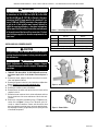
8. Refer to the instructions provided with the SIT Regulator Con-
version Kit, and Figure 1. Using a Torx T20 driver (with 1/4”
shank) or slotted screwdriver, remove and discard the three
pressure regulator mounting screws, pressure regulator tower,
the diaphragm assembly (if applicable) and the spring. Discard
all removed components.
IMPORTANT
The burner orifice provided in this kit are only for use
at elevations of 0 to 2,000 feet (610 M) in the USA
and 0 to 4,500 feet (0-1372 M) in Canada. At higher
elevations the BTU input must be de-rated by 4% for
every 1,000 feet (305 M) to maintain the proper ratio
of gas to air. If the installer must convert the unit to
adjust for varying altitudes, a deration information
sticker must be filled out by the installer and adhered
to the appliance at the time of the conversion. Contact
your local gas supplier for deration requirements for
your area.
Figure 1 - Valve Regulator Conversion
Figure 2 - Electronic Pilot
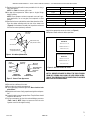
Figure 3 - Burner Orifice
Model Natural Gas
drill size*
Propane
drill size*
Aries35-C #48 (0.076”), Cat. No. J7910 #56 (0.046”), Cat. No. 62L37
Aries40-C #45 (0.082”), Cat. No. 39L66 #55 (0.052”), Cat. No. 19L52
Aries45-C #44 (0.086”), Cat. No. 60J80 #55 (0.052”), Cat. No. 19L52
* Standard size installed at factory
Table 2 - Burner Orifice Sizes, Elevation 0–4500 ft ( 0–1372 m)
Pilot
Orifice
Clip
Pilot
Orifice

900924-00NC 3
IHP.us.com
THIS APPLIANCE HAS BEEN CONVERTED TO:
INPUT BTU / HR - ##, ###
MANIFOLD PRESSURE - 3.5”
Orifice SIZE: ## (#.##”)
NATURAL GAS
THIS APPLIANCE HAS BEEN CONVERTED TO:
INPUT BTU / HR - ##, ###
MANIFOLD PRESSURE - 10”
ORIFICE SIZE: ## (#.##”)
PROPANE GAS
9. Replace the pilot orifice with the one provided in this kit using a
4mm allen wrench.
NOTE: See Table 2 for burner orifice sizes.
10. Use pipe joint compound or Teflon® tape on all pipe fittings
before installing.
NOTE: Ensure propane resistant compounds are used in pro-
pane applications, do not use pipe joint compounds on flare
fittings.
11. Retrieve the burner and hold the venturi tube above the orifice.
Place the shutter adjusting rod in the slot of the shutter arm
(Figure 4). Set the burner assembly into its position and secure
with the two screws previously removed.
INNOVATIVE HEARTH PRODUCTS • ARIES -C DIRECT VENT GAS FIREPLACES • GAS CONVERSION KIT INSTALLATION INSTRUCTIONS
3
12. Reinstall the sub floor with screws.
13. Reassemble the remaining components.
14. Turn on gas supply and test for gas leaks. Never check for leaks
with a flame!
15. Relight the main burner. Verify proper burner ignition and opera-
tion.
16. Inspect the pilot system for proper flame. The pilot flame should
engulf the flame sensor.
17. Using a manometer, test the inlet and manifold gas pressures
(Table 3 and 4). NOTE: Always test pressures with the valve
regulator control at the highest setting.
Burner Tube
Adjustment
Set-Screw
Air Shutter
Adjustment Rod Down
(Fully-Open Position)
Adjustment Rod Up
(Fully-Closed Position)
Figure 4 - Air shutter adjustment rod
Fuel Minimum Maximum
Natural Gas 5” WC / (1.25 kPa) 10.5” WC / (2.61 kPa)
Propane 11.0” WC / (2.74 kPa) 13.0” WC / (3.23 kPa)
Table 3 - Inlet Gas Supply Pressure
Fuel Pressure
Natural Gas 3.5” WC / (0.87 kPa)
Propane 10.0” WC / (2.49 kPa)
Table 4 - Manifold Gas Supply Pressure
18. Affix the appropriate conversion label (see Figure 6).
19. Replace facade and barrier before operation.
Figure 6 - Affix Gas Conversion Sticker
NOTE: A BARRIER DESIGNED TO REDUCE THE RISK OF BURNS
FROM HOT VIEWING GLASS SHALL BE USED DURING OPERA-
TION OF THIS FIREPLACE FOR THE PROTECTION OF CHILDREN
AND OTHER AT-RISK INDIVIDUALS.
Figure 5 - Burner Flame Appearance
No Blue Flame
Center
Soot at
Flame Tip
Dark Orange
Flame
IMPROPERLY
BURNING FLAME
Soot above
Flame Tip No Soot at
Flame Tip
PROPERLY
BURNING FLAME
Semi-Transparent
Yellow Flame
Blue Flame
Center

4
INNOVATIVE HEARTH PRODUCTS • ARIES -C DIRECT VENT GAS FIREPLACES • GAS CONVERSION KIT INSTALLATION INSTRUCTIONS
Printed in U.S.A. © 2018 Innovative Hearth Products
P/N 900924-00 Rev. NC 10/2018
Innovative Hearth Products (IHP) reserves the right to make changes at any time, without notice,
in design, materials, specifications, prices and also to discontinue colors, styles and products.
Consult your local distributor for fireplace code information.
1769 East Lawrence Street • Russellville, AL 35654
-
 1
1
-
 2
2
-
 3
3
-
 4
4


Astria Fireplaces Aries Instruction Sheet
- Catégorie
- Cheminées
- Taper
- Instruction Sheet
dans d''autres langues
- English: Astria Fireplaces Aries
Documents connexes
-
Astria Fireplaces Aries Instruction Sheet
-
-
-
-
-
-
-
-
-
Autres documents
-
Superior Fireplaces DRT4200 Mode d'emploi
-
-
-
-
-
-
Superior DRT2045 Installation And Operation Instructions Manual