
Instruction Manual

Preface
- i -
Thank you for purchasing this product.
Before using this product, read this document carefully so that you can use this product correctly and safely.
Preface

For safe usage
- ii -
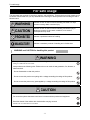
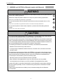
This document uses symbols for warnings, cautions, and prohibitions. These symbols and their meanings are
as follows. Please make sure you fully understand the meanings of these symbols before reading the rest of
this document.
For safe usage
WARNING
Indicates an item for which incorrect handling can result in a major
accident involving death or serious injury.
CAUTION
Indicates an item for which incorrect handling can lead to injury or
damage to property. Under certain conditions, more serious
consequences may result.
PROHIBITED
Indicates a prohibited method of handling.
MANDATORY
Indicates a mandatory method of handling and a forcible item.
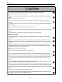
WARNING and CAUTION for handling this product
WARNING
Do not perform any work while the vehicle is running.
Doing so could result in an accident.
Always observe the following rules. Failure to do so can result in heat generation, fire, blowout, or
electrical shock.
- Do not disassemble or alter this product.
- Do not connect this product to anything with a voltage exceeding the ratings of this product.
- Do not connect the probe to any parts applied by a voltage exceeding the ratings of this product.
CAUTION
<Work environment>
Do not work anywhere that water could come in contact with the product and equipment.
Block the wheels of the vehicle with chocks before carrying out work.
Failure to do so could result in an accident.

For safe usage
- iii -
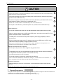
CAUTION
When working anywhere hardly visible, for example under the vehicle, always make the vehicle
starter switch (ignition switch) OFF to ensure that the vehicle cannot be moved.
Failure to do so could result in an accident.
When working near the engine compartment, be careful of the engine and other high-temperature
parts.
High-temperature parts can cause burns.
Do not route the cable of this product over the engine compartment, especially if the engine is
running.
Failure to follow this instruction could result in an accident by catching up the cable and clothes with the
belt and pulley.
Do not use this product in an extremely dusty environment.
The response of the LCD may be slow at the low temperature place. (Caution for the models with
LCD)
This phenomenon is attributed to the characteristics of the LCD and not a failure.
<Checking before use>
Inspect for adhesion of foreign materials to or pin breakage of each connector of this product
before use.
Before connecting the datalink cable to this product and the vehicle side diagnosis connector,
inspect to see if each connector is contaminated with foreign materials or the connector pins are
damaged.
Before using the SD memory card, inspect to see if any foreign materials are stuck in the SD
memory card slot or the contact surface of the SD memory card is contaminated with foreign
materials. (Caution for the models with LCD)
<Handling of the product and equipment>
Do not drop this product or subject it to a strong impact.
When connecting the datalink cable to this product and the vehicle side diagnosis connector or
disconnecting it from them, ensure correct orientation of the connector and gently put it straight in.
If the connector is connected in the wrong orientation, or put in or pulled out at the wrong angle, there is a
risk of damaging the connector terminal and this may cause malfunctioning of the vehicle and/or this
product.
When connecting the USB cable to this product and a PC or disconnecting it from them, ensure
correct orientation of the connector and gently put it straight in.
If the connector is connected in the wrong orientation, or put in or pulled out at the wrong angle, there is a
risk of damaging the connector terminal and this may cause malfunctioning of the PC and/or this product.
When pulling out the connector of datalink cable or USB cable, hold the connector section not the
cord.
Pulling on the cord section can break the lines in the cable.
Do not lift or drag this product by holding the cable connected to this product. When moving or
installing, move this product by holding with hands.

For safe usage
- iv -
The product shall be disposed in accordance with all applicable legislation for disposal of Electrical and Electronic
Equipment in each country and region. (e.g. WEEE Directive in EU)
Please contact our authorized distributor or our sales agent when disposing it.
CAUTION
Do not apply the load causing stress to the connector connected to this product.
Applying too much force could result in breaking the connector terminal and this may cause malfunctioning
of the vehicle, the PC and/or this product.
Do not insert anything other than an SD memory card in the SD memory card slot on this product.
(Caution for the models with LCD)
Do not turn the power of this product OFF or remove the SD memory card while the SD memory
card indicator is flashing. (Caution for the models with LCD)
Failure to do so results in failure of the SD memory card or loss of the data in it.
Do not pull out an SD memory card when power is on. (Caution for the models with LCD)
<Usage restrictions>
Do not use a datalink cable other than the dedicated datalink cable supplied with this product.
When you start this product only by USB power (BUS power), be careful not to set the PC to "low
power consumption mode" / "suspend mode".
The USB port to be connected to this product requires a power supply capability of 500 mA
current source.
As for connecting this product to the PC, directly connect it to the USB port on the PC or via a
USB hub that has the capability of supplying sufficient current.
Some types of USB hubs may have insufficient power supply capability for normal operation. (For
example, a hub on PC keyboard is not suitable for this connection.)
<Storage and maintenance of the product>
Do not expose this product to direct sunlight for long periods of time.
The backlight of the LCD may be deteriorated and its luminance could be reduced consequently
in a high humid environment. (Caution for the models with LCD)
Use and store this product in a dry environment.
Do not use solvents or thinners such as benzine when cleaning.
To do so could cause deformation, discoloration, cracking, etc., and also result in loss of functions. To
clean, wipe gently with a soft damp cloth with diluted neutral detergent.
<Disposal of the product>
When discarding the product or its accessories, contact authorized industrial waste-disposal
service.
Those who discard waste without authorization will be punished by law.
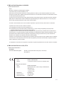
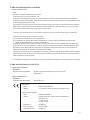
Disposal Requirements

For safe usage
- v -
WARNING and CAUTION for Bluetooth (models with Bluetooth)
WARNING
Do not use this product near medical devices or inside medical facilities as it may affect electronic
devices with medical applications.
Make sure to keep this product at least 22 cm away from persons wearing a pacemaker.
Radio wave could affect the performance of pacemaker.
Do not use this product near an automatic control device such as an automatic door or a fire
alarm.
Radio wave could effect its operation and result in an accident caused by malfunction.
Do not use this product in electric trains, airplanes, or places where flammable gasses are
present.
Failure to do so may result in accidents.
CAUTION
The communication range depends on any obstacles (i.e., human bodies, metal, walls) between
this product and the Bluetooth device, and the condition of the radio wave.
An antenna is built into this product. The sensitivity of the Bluetooth communication is maximized
when no obstacles exist between the connected Bluetooth device and the antenna of this product.
The communication distance becomes shorter should there be obstacles between the antenna of
the connected Bluetooth device and the built-in antenna of this product.
The following circumstances could affect the sensitivity of the Bluetooth communication.
- Obstacles such as human body, metal, wall, etc.
- In close proximity to established wireless networks, microwave ovens, and other devices that
emit radio waves.
Since Bluetooth devices and the wireless LAN (IEEE802.11 b/g) use the same frequency band
(2.4 GHz), radio wave interference could occur and cause degradation of communication speed,
noise and disconnection if a Bluetooth device is used near a wireless LAN equipped device.
To resolve poor communications, perform the following steps.
- Place this product as close to a Bluetooth device as possible.
- Keep a wireless LAN equipped device away from this product as much as possible.
- If communications do not improve, turn off any wireless LAN equipped devices nearby.
Use the USB cable for more data critical situation over the Bluetooth communication (wireless)
due to the greater possibility of loss of connection during data upload or download of the data
transmission.
Please note that we shall have no liability for any information leakage from the Bluetooth
communication.

For safe usage
- vi -
Japan, USA, Canada, Australia, New Zealand, EU (Europian Union), Malaysia, Indonesia
* In the countries other than those above, you cannot use the models with Bluetooth.
Microsoft, Windows
®
, Internet Explorer, Windows 10, Windows 8.1, Windows 7 are the trademarks or
registered trademarks of the Microsoft Corporation of the United States in the United States and other
countries.
Bluetooth
®
is the trademark or registered trademark of Bluetooth SIG, Inc. in the United State and other
countries.
SD Memory Card
TM
and SDHC Memory Card
TM
are the registered trademarks of Panasonic
Corporation, SanDisk Corporation in the United State and Toshiba Corporation.
Names of products and companies in this document are registered trademarks or trademarks of their
owners.
TRON, iTRON and
µiTRON are not the names for specific products and series of products.
TRON is an abbreviation of "The Real-time Operating System Nucleus".
µiTRON is an abbreviation of "Micro Industrial TRON".
The countries where you can use the models with Bluetooth
Trademarks

Table of contents
- vii -
1 Before Use
1-1 Product Configuration .......................................................................................................................... 1
Components............................................................................................................................................1
1-2 Names of the Parts .............................................................................................................................. 2
models with LCD ..................................................................................................................................... 2
1-3 Setup.................................................................................................................................................... 3
Required operating environment of the PC.............................................................................................3
Necessary Setup..................................................................................................................................... 4
1-4 Connection........................................................................................................................................... 5
Connecting to the vehicle........................................................................................................................ 5
Connecting to a PC .................................................................................................................................6
1-5 SD Memory Card ................................................................................................................................. 7
Inserting/removing an SD memory card..................................................................................................7
2 Basic Operations
2-1 Starting................................................................................................................................................. 8
2-2 Ending.................................................................................................................................................. 9
3 Indicator
3-1 Indicator ............................................................................................................................................. 10
4 Product Specifications
4-1 Specifications of This Product............................................................................................................ 11
5 Warranty
5-1 Warranty............................................................................................................................................. 12
Table of contents

1 Before Use
- 1 -
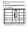
1 Before Use
Check that you have all of the following standard components before using this product.
Set Part Number: 95171-0110* (with LCD, with Bluetooth)
1-1 Product Configuration
Components
No. Part Name Illustration Part No. Q'ty
1 Main unit
with LCD
–1
2 Datalink Cable 95171-1284* 1
3 USB Cable 95171-1011* 1
4 USB Spacer 95171-1302* 1
5 SD memory card 95171-1324* 1
6 Instruction Manual (this document) – 1
NOTE
The last figure of a part No. is indicated with *. When you ask for information, make inquiries with the
9-digit part No. and part name.
T01856Z
T01857Z
T01871Z
T02747Z
T02715Z

1 Before Use
- 2 -
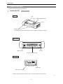
The names of the product parts are as follows:
1-2 Names of the Parts
models with LCD
Overall
LCD
A key
Up/Down/Right/Left keys
Indicators
* For detailed information about indicators, refer to "Chapter 3 Indicator/3-1 Indicator".
B key
* Rubber caps are provided for "USB connector", "DC jack" and "SD memory card slot".
T02517E
USB connector*
SD memory card slot*
Mode switch
DC jack*
Connector for datalink cable
Upper side
Right side

1 Before Use
- 3 -
You must carry out the setup necessary for use of this product.
.
For using this product, a PC with following operating environments is required.
•OS:
Microsoft Windows 7 (SP1) (32bit, 64bit) English version
Microsoft Windows 8.1 (32bit, 64bit) English version
Microsoft Windows 10 (32bit, 64bit) English version
• With USB 2.0 interface as standard
• Internet Explorer 11.0 or later version should be installed.
• Access to Internet is allowed. (Broadband internet connection is recommended)
Confirm the latest information in the following website.
http://www.ds3.denso.co.jp/dst-i/dst-i.html
1-3 Setup
Required operating environment of the PC
NOTE
If this product is used as the interface, the operating environment of the software on a PC side is
needed in addition to the above operating environment.

1 Before Use
- 4 -
For using this product, following setup is needed.
Installing DST-i setup software to a PC (all models)
A dedicated USB driver, the setup utility (DST-i configuration tool), etc. which is required for connecting this
product and a PC using a USB cable or Bluetooth shall be installed to the PC.
Installing the DST-i main unit software to this product (all models)
Install the DST-i main unit software to this product.
Installing Bluetooth driver software and Paring to a PC (models with Bluetooth)
For the models with Bluetooth, to connect this product with a PC through the Bluetooth communication function,
you must install the Bluetooth driver software to the PC beforehand.
In addition, you must execute pairing between the PC and this product.
1. Access the following website and setup the this product and the PC following the displayed
instructions.
http://www.ds3.denso.co.jp/dst-i/setup/
Necessary Setup
CAUTION
Do not connect this product with a PC using the USB cable before the DST-i setup software
installation to your PC is completed.
To install the DST-i setup software to a PC, log on with administrator privileges and close all running
applications before installation.
In installing the DST-i main unit software, execute the install by using the USB cable in the state that
this product and the PC are connected.
Do not execute the install in using Bluetooth communication.
Use of a Bluetooth driver software equipped as standard to the PC with Microsoft
®
Windows
®
operating system is recommended for use of a Bluetooth communication.
This information does not guarantee the connection between all of commercially available
Bluetooth modules and information terminals equipped with Bluetooth (e.g., PC and cellular
phone).
Use a Bluetooth module that is labeled with the Bluetooth logo mark and conforms to the Bluetooth
standard 2.0.
Total eight Bluetooth modules and information terminals having Bluetooth can execute paring with
this product. If ninth Bluetooth module or information terminal executes paring, first Bluetooth
module or information terminal will be cancelled.

1 Before Use
- 5 -
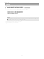
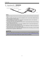
Use the datalink cable to connect this product with the vehicle.
Check the position of the diagnosis connector of the vehicle side in the repair manual of the vehicle.
1. First, connect this product and the datalink cable.
2. Next, connect the datalink cable to the vehicle side diagnosis connector.
1-4 Connection
Connecting to the vehicle
CAUTION
Perform the connection of step 1 and step 2 according to the order.
NOTE
The power supply of this product is turned ON by turning the mode switch ON after connected
with the vehicle.
[1] Connected to this product
Tighten with screws.
Notch (Center)
T02929E
[2] Connected to vehicle side diagnosis connector

1 Before Use
- 6 -
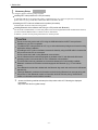
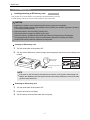
Use a USB cable to connect this product to a PC.
Connecting to a PC
NOTE
The power supply of this product is turned ON by turning the mode switch ON after connected with a
PC.
When the USB communication with the PC is established, the PC communication (USB) indicator on
this product lights or flashes in green.
When establishing the connection with the Bluetooth communication function on the models with
Bluetooth, USB cable connection is not needed.
If connecting with a PC with the Bluetooth communication, communication setup must be performed
with the DST-i configuration tool.
When the Bluetooth communication with the PC is established, the PC communication (Bluetooth)
indicator on this product lights or flashes in blue.
When connecting the model with Bluetooth to a PC with the USB cable, the USB communication has
the top priority in the communication between a PC.
When communication way is changed from USB to Bluetooth while communicating, remove the USB
cable with the PC application software finished.
CAUTION
You must install the DST-i setup software on your PC before you connect the USB cable to your PC.
Reference: Page 4 Installing DST-i setup software to a PC (all models) (Chapter 1 Before Use/Setup/Necessary Setup)
When the PC does not supply adequate power, please contact your distributor.
T02006E
USB cable
Connected to the USB connector into the PC

1 Before Use
- 7 -
This product can use an SD memory card inserting it into the SD memory card slot.
The SD memory card may be used to install software or store vehicle data.
Inserting an SD memory card
1. Turn the mode switch of this product OFF.
2. Turn the notch of SD memory card to the right and insert gently to the slot end until a clicking noise
is heard.
Removing an SD memory card
1. Turn the mode switch of this product OFF.
2. Push the SD memory card lightly.
3. The SD memory card is ejected a little. Pull out it gently.
1-5 SD Memory Card
Inserting/removing an SD memory card
CAUTION
Depending on software, some functions with SD memory cards are not available.
Refer to the instruction manual of the software to know whether your software supports the functions
or not and the handling method.
Use an SD memory card or an SDHC memory card.
This product does not support an SDXC memory card.
Use an SD memory card labeled with the SD logo mark and conforming to the SD standard.
The following brand SD memory cards are recommended: Panasonic, SanDisk and Toshiba
Not all the SD memory cards are supported on this product.
NOTE
If the notch on the SD memory card side face is set to the "Lock" position, data storage and
deletion are disabled by the write protect function (write inhibit). Make sure to unlock the write
protect function before use.
T02085E
Notch to be on
the right side
Confirm the logo mark of
the card.
SDHC
SD
Available card

2 Basic Operations
- 8 -
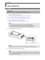
2 Basic Operations
1. Connect the datalink cable to this product.
Reference: Page 5 Connecting to the vehicle (Chapter 1 Before Use/Connection)
2. Connect the datalink cable to the vehicle side diagnosis connector.
Reference: Page 5 Connecting to the vehicle (Chapter 1 Before Use/Connection)
3. Connect this product and a PC with the USB cable.
Reference: Page 6 Connecting to a PC (Chapter 1 Before Use/Connection)
4. Turn the mode switch of this product ON.
5. Turn the vehicle starter switch (ignition switch) ON.
2-1 Starting
CAUTION
Perform the connection of step 1 and step 2 according to the order.
NOTE
If you do not use a PC, you do not need to connect with the USB cable.
If you use a model with Bluetooth and connect with a PC through the Bluetooth
communication function, you do not need to connect with the USB cable.
NOTE
When turning the mode switch ON, the power indicator of this product turns green.
NOTE
When the vehicle starter switch (ignition switch) position is OFF or ACC, communication with
the vehicle cannot be established. Turn the vehicle starter switch (ignition switch) ON or start
the engine when using this product.
T01897E
Mode switch

2 Basic Operations
- 9 -
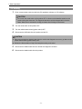
1. Finish communications with the vehicle by PC application software or LCD software.
2. Turn the mode switch of this product OFF.
3. Turn the vehicle starter switch (ignition switch) OFF.
4. Disconnect the USB cable from this product and the PC.
5. Disconnect the datalink cable from the vehicle side diagnosis connector.
6. Disconnect the datalink cable from this product.
2-2 Ending
CAUTION
Do not turn the mode switch of this product OFF or disconnect the datalink cable from this
product during the active test. The diagnosed actuators could be stopped still in the drive
status. Make sure to execute the ending procedure after finishing the active test.
CAUTION
When disconnecting the datalink cable from the vehicle side diagnosis connector, go after turn the
vehicle starter switch (ignition switch) OFF.
Perform the disconnection of step 5 and step 6 according to the order.

3 Indicator
- 10 -
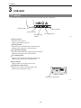
3 Indicator
The indicators of this product provide the following information by their illumination.
[Power] indicator
Shows the status of power.
Lights in green during power ON.
[Vehicle] indicator
Shows the status of communications with the vehicle.
Flashes in green during active communications.
[PC (Bluetooth)] indicator
Shows the status of Bluetooth communications with the PC.
Flashes in blue during active communications.
[PC (USB)] indicator
Shows the status of USB communications with the PC.
Flashes in green during active communications.
[Error] indicator
Lights or flashes in red when an error occurs.
[SD Memory Card] indicator
Shows the access status of the SD memory card.
Flashes in green during active access.
3-1 Indicator
T01900E
[Power] indicator
[Vehicle] indicator
[PC (USB)] indicator
[PC (Bluetooth)]
indicator
[Error] indicator
T01917E
[SD memory card] indicator

4 Product Specifications
- 11 -
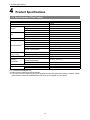
4 Product Specifications
*1 For models with Bluetooth only
*2 Some functions require the support software.
*3 This product can be turned on by the power supplied from the USB power (BUS power). However, vehicle
communication cannot be established when the power is not supplied from the vehicle.
4-1 Specifications of This Product
Item Specifications
OS
µiTRON
CPU 32-bit RISC microcomputer
Memory
Built-in Flash ROM 16 MB
SDRAM 16 MB
EEPROM 32 KB
LCD
Size 2.7 inch TFT color LCD
Resolution QVGA (320 x 240 dots)
Display color Max. 260000 colors
Input device Operation keys 6 keys
External interface
*2
USB USB 2.0 x 1
Bluetooth
*1
Bluetooth 2.0
SD memory card Slot x 1 (supporting SD and SDHC memory cards)
DC jack JEITA4 standard type
Vehicle communication
Dedicated connector (D-sub 25 pin) x 1
ISO9141, CAN
Main unit power
supply voltage
Vehicle power supply DC 6.5 to 32 V (Datalink cable)
USB power (BUS power)
DC 4.75 to 5.25 V
*3
Power consumption Normally 1.5 W (12 VDC), Max. 2.5 W (12 VDC)
Operating
environment
Operating temperature
[Storage temperature]
0 to 50°C [-10 to 60°C]
Operating humidity 35 to 85% (No condensation)
Dimensions 135 mm (W) x 70 mm (H) x 35 mm (D)
Weight
Model without Bluetooth Approx. 225 g
Model with Bluetooth Approx. 230 g

5 Warranty
- 12 -
5 Warranty
1. The warranty period of this set is two years after the purchase day. However accessories are not covered, main
body only.
2. Free repair warranty is applied only for the failure under proper operation conditions within the warranty period.
3. Non-free repair is applied to the following cases even if the valid warranty period remains.
• Failure or damage from fire and natural disaster.
• Failure or damage as a result of a falling during transportation and movement after purchase or from the
improper handling.
• Failure or damage caused from handling in a way contrary to proper operating methods and cautions described
in this document.
• Failure or damage from modification or liability for operations.
• Replacement of external parts such as the resin case.
4. We shall have no liability for any direct or indirect damage resulting from failure or use of this product.
5. For request of repair, please contact your distributor.
Data preservation
Recorded data in this product could be lost in repair. Please note that we shall have no liability for any damage and
data preservation derived in conjunction with data loss.
5-1 Warranty
La page est en cours de chargement...
La page est en cours de chargement...
La page est en cours de chargement...
La page est en cours de chargement...
La page est en cours de chargement...
La page est en cours de chargement...
La page est en cours de chargement...
La page est en cours de chargement...
-
 1
1
-
 2
2
-
 3
3
-
 4
4
-
 5
5
-
 6
6
-
 7
7
-
 8
8
-
 9
9
-
 10
10
-
 11
11
-
 12
12
-
 13
13
-
 14
14
-
 15
15
-
 16
16
-
 17
17
-
 18
18
-
 19
19
-
 20
20
-
 21
21
-
 22
22
-
 23
23
-
 24
24
-
 25
25
-
 26
26
-
 27
27
-
 28
28


dans d''autres langues
- English: Denso DST-I User manual
Documents connexes
Autres documents
-
Panasonic CF-U1 Manuel utilisateur
-
-
Hyundai Kona Manuel utilisateur
-
-
-
Samsung n100sp Manuel utilisateur
-
-
-