La page est en cours de chargement...

Pre - Installation Notes
Follow all naonal and local building and electrical
codes.
Transformer must be plugged into a GFCI outlet.
Transformer can support up to 12 was.
Do not cut any wires. Any extra wire length can be
coiled up.
Do not use extension cords.
Do not use within 10 feet of ponds, pools, or spas.
Cover the photocell sensor with dark tape to make
the lights work while tesng.
If using insulated wire staples to hold the wires in
place, be sure not to pierce or crush the wires.
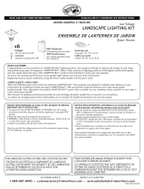
Step 1
Prepare the Transformer
1.1 Properly align the photocell plug with the transformer
receptacle and firmly push the plug into place.
1.2 Tighten the plasc nut by turning clockwise. If the
photocell is already aached, check to make sure
plasc nut is completely ght for a weatherproof seal.
Step 2
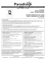
Mount the Transformer and Photocell
2.1 Use (4) #4 x ½“ screws (not supplied) to mount
transformer to an exterior wall surface or deck face a
minimum of 12” above ground level. Plug the
transformer into the GFCI outlet.
2.2 Mount the round photocell holder next to the
transformer with the supplied screw. Ensure the
locaon of the photocell can sense dusk and dawn.
2.3 Peel off the protecve film covering the adhesive on
the top surface of the round photocell holder. Align
the photocell and press firmly onto the adhesive.
2.4 To test the power supply during installaon,
temporarily cover the photocell sensor with dark
tape so the lights will come on during installaon.
Be sure to remove the tape for normal operaon.
(Locaon of Photocell Sensor shown in picture 2.3.)
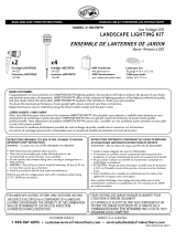
Step 3
Plug in Tee Connector
3.1 Run the 9’ power cable from the photocell to the
locaon of the first light fixture. If needed, the
power cable can fit through a 1/2” hole.
3.2 Plug the output connector from the photocell into
the supplied T-Connector. Press firmly unl the
connecon is fully engaged.
3.3 Connecon is fully engaged when there is minimal
gap between the output and Tee connectors.
3.4 Connect light fixtures per their instrucons.
3.5 Any unused Tee Connector terminals or spliers in
the system must be sealed using the aached cap.
12 Volt 12 Watt DC Transformer
INST#: XIS12WL-REV 1-15
Transformateur
Photocellule
Connecteur en T
Minimum 12 po au-dessus du sol
Photocellule
Capteur
Sortir
Connecteur
9 pi de
puissance
Câble
Pre - Installation Notes
Follow all naonal and local building and electrical
codes.
Transformer must be plugged into a GFCI outlet.
Transformer can support up to 12 was.
Do not cut any wires. Any extra wire length can be
coiled up.
Do not use extension cords.
Do not use within 10 feet of ponds, pools, or spas.
Cover the photocell sensor with dark tape to make
the lights work while tesng.
If using insulated wire staples to hold the wires in
place, be sure not to pierce or crush the wires.
Step 1
Prepare the Transformer
1.1 Properly align the photocell plug with the transformer
receptacle and firmly push the plug into place.
1.2 Tighten the plasc nut by turning clockwise. If the
photocell is already aached, check to make sure
plasc nut is completely ght for a weatherproof seal.
Step 2
Mount the Transformer and Photocell
2.1 Use (4) #4 x ½“ screws (not supplied) to mount
transformer to an exterior wall surface or deck face a
minimum of 12” above ground level. Plug the
transformer into the GFCI outlet.
2.2 Mount the round photocell holder next to the
transformer with the supplied screw. Ensure the
locaon of the photocell can sense dusk and dawn.
2.3 Peel off the protecve film covering the adhesive on
the top surface of the round photocell holder. Align
the photocell and press firmly onto the adhesive.
2.4 To test the power supply during installaon,
temporarily cover the photocell sensor with dark
tape so the lights will come on during installaon.
Be sure to remove the tape for normal operaon.
(Locaon of Photocell Sensor shown in picture 2.3.)
Step 3
Plug in Tee Connector
3.1 Run the 9’ power cable from the photocell to the
locaon of the first light fixture. If needed, the
power cable can fit through a 1/2” hole.
3.2 Plug the output connector from the photocell into
the supplied T-Connector. Press firmly unl the
connecon is fully engaged.
3.3 Connecon is fully engaged when there is minimal
gap between the output and Tee connectors.
3.4 Connect light fixtures per their instrucons.
3.5 Any unused Tee Connector terminals or spliers in
the system must be sealed using the aached cap.
12 Volt 12 Watt DC Transformer
INST#: XIS12WL-REV 1-15
Transformateur
Photocellule
Connecteur en T
Minimum 12 po au-dessus du sol
Photocellule
Capteur
Sortir
Connecteur
9 pi de
puissance
Câble
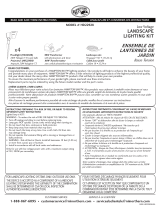
TRANSFORMATEUR DC 12 VOLTS 12 WATTS
INSTRUCTIONS D'INSTALLATION
Étape 1: Alignez correctement la fiche de la cellule photoélectrique avec la
prise du transformateur et poussez fermement la fiche en place (fig. 1).
Étape 2: Serrez l'écrou en plastique en le tournant dans le sens des aiguilles
d'une montre (fig. 2). Si la cellule photoélectrique est déjà fixée, assurez-vous
que l'écrou en plastique est complètement serré pour un joint étanche.
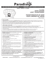
Étape 3: Utilisez (4) vis #4 x 1⁄2 po (non fournies) pour monter le
transformateur sur une surface de mur extérieur ou sur une terrasse à au
moins 12 po au-dessus du niveau du sol. Branchez le transformateur dans la
prise GFCI (fig. 3 et 4).
Étape 4: Montez le support de photocellule rond à côté du transformateur
avec la vis fournie (fig. 5). Assurez-vous que l'emplacement de la cellule
photoélectrique peut détecter le crépuscule et l'aube. N'installez pas le
capteur photo derrière des arbustes. Cela affectera le capteur photo. Le
capteur photo ne fonctionnera pas correctement s'il est installé trop près
d'une source lumineuse.
Étape 5: Retirez le film protecteur recouvrant l'adhésif sur la surface
supérieure du support de cellule photoélectrique rond. Alignez la cellule
photoélectrique et appuyez fermement sur l'adhésif (fig. 6).
Étape 6: Pour tester l'alimentation électrique pendant l'installation, couvrez
temporairement le capteur de la cellule photoélectrique avec du ruban
adhésif foncé afin que les lumières s'allument pendant l'installation. Assurez-
vous de retirer la bande pour un fonctionnement normal. (Emplacement du
capteur de cellule photoélectrique illustré à la fig. 6.)
Étape 7: Faites passer le câble d'alimentation de 9 pi de la cellule
photoélectrique à l'emplacement du premier luminaire. Si nécessaire, le
câble d'alimentation peut passer par un trou de 1/2 po (fig. 7).
Étape 8: Branchez le connecteur de sortie de la cellule photoélectrique dans
le connecteur en T fourni. Appuyez fermement jusqu'à ce que la connexion
soit complètement engagée (fig. 8).
Étape 9: La connexion est entièrement engagée lorsqu'il y a un écart
minimal entre la sortie et les connecteurs en T (fig. 9).
Étape 10: Connectez les luminaires selon leurs instructions.
Étape 11: Toutes les bornes ou répartiteurs de connecteur en T inutilisés
dans le système doivent être scellés à l'aide du capuchon joint (fig. 10).
Instructions d'installation
Pre - Installation Notes
Follow all naonal and local building and electrical
codes.
Transformer must be plugged into a GFCI outlet.
Transformer can support up to 12 was.
Do not cut any wires. Any extra wire length can be
coiled up.
Do not use extension cords.
Do not use within 10 feet of ponds, pools, or spas.
Cover the photocell sensor with dark tape to make
the lights work while tesng.
If using insulated wire staples to hold the wires in
place, be sure not to pierce or crush the wires.
Step 1
Prepare the Transformer
1.1 Properly align the photocell plug with the transformer
receptacle and firmly push the plug into place.
1.2 Tighten the plasc nut by turning clockwise. If the
photocell is already aached, check to make sure
plasc nut is completely ght for a weatherproof seal.
Step 2
Mount the Transformer and Photocell
2.1 Use (4) #4 x ½“ screws (not supplied) to mount
transformer to an exterior wall surface or deck face a
minimum of 12” above ground level. Plug the
transformer into the GFCI outlet.
2.2 Mount the round photocell holder next to the
transformer with the supplied screw. Ensure the
locaon of the photocell can sense dusk and dawn.
2.3 Peel off the protecve film covering the adhesive on
the top surface of the round photocell holder. Align
the photocell and press firmly onto the adhesive.
2.4 To test the power supply during installaon,
temporarily cover the photocell sensor with dark
tape so the lights will come on during installaon.
Be sure to remove the tape for normal operaon.
(Locaon of Photocell Sensor shown in picture 2.3.)
Step 3
Plug in Tee Connector
3.1 Run the 9’ power cable from the photocell to the
locaon of the first light fixture. If needed, the
power cable can fit through a 1/2” hole.
3.2 Plug the output connector from the photocell into
the supplied T-Connector. Press firmly unl the
connecon is fully engaged.
3.3 Connecon is fully engaged when there is minimal
gap between the output and Tee connectors.
3.4 Connect light fixtures per their instrucons.
3.5 Any unused Tee Connector terminals or spliers in
the system must be sealed using the aached cap.
12 Volt 12 Watt DC Transformer
INST#: XIS12WL-REV 1-15
Transformateur
Photocellule
Connecteur en T
Minimum 12 po au-dessus du sol
Photocellule
Capteur
Sortir
Connecteur
9 pi de
puissance
Câble
Préparation
• Respectez tous les codes nationaux et locaux du bâtiment et de l'électricité.
• Le transformateur doit être branché sur une prise GFCI marquée
«emplacement humide».
• Le transformateur peut supporter jusqu'à 12 watts. (30) lumières de 0,4
watts.
• Ne coupez aucun fil. Toute longueur de fil supplémentaire peut être enroulée.
• N'utilisez pas de rallonges.
• Ne pas utiliser à moins de 10 pieds des étangs, piscines ou spas.
• Couvrez le capteur de la cellule photoélectrique avec du ruban adhésif foncé
pour que les lumières fonctionnent pendant le test.
• Si vous utilisez des agrafes isolées pour maintenir les fils en place, assurez-
vous de ne pas percer ou écraser les fils.
• Il n'y a aucune pièce réparable à l'intérieur du bloc d'alimentation. Ne pas
désassembler.
fig. 1 fig. 2
LES DIAGRAMMES ET LES INSTRUCTIONS DE CETTE BROCHURE SONT À DES FINS D'ILLUSTRATION UNIQUEMENT ET NE SONT PAS DESTINÉS À REMPLACER UN PROFESSIONNEL AGRÉÉ. TOUTE CONSTRUCTION OU UTILISATION DU PRODUIT DOIT ÊTRE
CONFORME À TOUS LES CODES DE ZONAGE ET/OU DE CONSTRUCTION LOCAUX. LE CONSOMMATEUR ASSUME TOUS LES RISQUES ET RESPONSABILITÉS ASSOCIÉS À LA CONSTRUCTION OU À L'UTILISATION DE CE PRODUIT. LE CONSOMMATEUR OU
L'ENTREPRENEUR DOIT PRENDRE TOUTES LES MESURES NÉCESSAIRES POUR ASSURER LA SÉCURITÉ DE TOUTES LES PERSONNES IMPLIQUÉES DANS LE PROJET, Y COMPRIS, MAIS SANS S'Y LIMITER, LE PORT DE L'ÉQUIPEMENT DE SÉCURITÉ APPROPRIÉ.
À L'EXCEPTION DE CE QUI EST CONTENU DANS LA GARANTIE LIMITÉE ÉCRITE, LE GARANT NE FOURNIT AUCUNE AUTRE GARANTIE, EXPLICITE OU IMPLICITE, ET NE SERA PAS RESPONSABLE DES DOMMAGES, Y COMPRIS LES DOMMAGES INDIRECTS.
©2021 UFP Retail Solutions, LLC. Deckorators est une marque déposée de UFP Industries, Inc. aux États-Unis. Tous droits réservés.
68956 U.S. Highway 131, White Pigeon, MI 49099
13865 12/21
www.deckorators.com
Pre - Installation Notes
Follow all naonal and local building and electrical
codes.
Transformer must be plugged into a GFCI outlet.
Transformer can support up to 12 was.
Do not cut any wires. Any extra wire length can be
coiled up.
Do not use extension cords.
Do not use within 10 feet of ponds, pools, or spas.
Cover the photocell sensor with dark tape to make
the lights work while tesng.
If using insulated wire staples to hold the wires in
place, be sure not to pierce or crush the wires.
Step 1
Prepare the Transformer
1.1 Properly align the photocell plug with the transformer
receptacle and firmly push the plug into place.
1.2 Tighten the plasc nut by turning clockwise. If the
photocell is already aached, check to make sure
plasc nut is completely ght for a weatherproof seal.
Step 2
Mount the Transformer and Photocell
2.1 Use (4) #4 x ½“ screws (not supplied) to mount
transformer to an exterior wall surface or deck face a
minimum of 12” above ground level. Plug the
transformer into the GFCI outlet.
2.2 Mount the round photocell holder next to the
transformer with the supplied screw. Ensure the
locaon of the photocell can sense dusk and dawn.
2.3 Peel off the protecve film covering the adhesive on
the top surface of the round photocell holder. Align
the photocell and press firmly onto the adhesive.
2.4 To test the power supply during installaon,
temporarily cover the photocell sensor with dark
tape so the lights will come on during installaon.
Be sure to remove the tape for normal operaon.
(Locaon of Photocell Sensor shown in picture 2.3.)
Step 3
Plug in Tee Connector
3.1 Run the 9’ power cable from the photocell to the
locaon of the first light fixture. If needed, the
power cable can fit through a 1/2” hole.
3.2 Plug the output connector from the photocell into
the supplied T-Connector. Press firmly unl the
connecon is fully engaged.
3.3 Connecon is fully engaged when there is minimal
gap between the output and Tee connectors.
3.4 Connect light fixtures per their instrucons.
3.5 Any unused Tee Connector terminals or spliers in
the system must be sealed using the aached cap.
12 Volt 12 Watt DC Transformer
INST#: XIS12WL-REV 1-15
Transformateur
Photocellule
Connecteur en T
Minimum 12 po au-dessus du sol
Photocellule
Capteur
Sortir
Connecteur
9 pi de
puissance
Câble
fig. 9 fig. 10fig. 9 fig. 10
fig. 4
fig. 5 fig. 6
fig. 7 fig. 8
fig. 3
/