Sony VPL-CX80 Manuel utilisateur
- Catégorie
- Téléviseurs
- Taper
- Manuel utilisateur

Data Projector VPL-CX80
© 2004 Sony Corporation
2-178-203-11 (1)
Data Projector
GB
FR
ES
Operating Instructions
Mode d’emploi
Manual de instrucciones
VPL-CX80

GB
2
WARNING
To prevent fire or shock hazard, do
not expose the unit to rain or
moisture.
To avoid electrical shock, do not
open the cabinet. Refer servicing to
qualified personnel only.
For the customers in the USA
If you have any questions about this product,
you may call:
Sony Customer Information Service Center
1-800-222-7669 or http://www.sony.com/
The number below is for FCC related
matters only.
Declaration of Conformity
Trade Name: SONY
Model No.: VPL-CX80
Responsible Party: Sony Electronics Inc.
Address: 16450 W. Bernardo Dr, San Diego,
CA 92127 U.S.A.
Telephone Number: 858-942-2230
This device complies with Part 15 of the
FCC Rules. Operation is subject to the
following two conditions: (1) This device
may not cause harmful interference, and (2)
this device must accept any interference
received, including interference that may
cause undesired operation.
This equipment has been tested and found to
comply with the limits for a Class B digital
device, pursuant to Part 15 of the FCC
Rules. These limits are designed to provide
reasonable protection against harmful
interference in a residential installation.
This equipment generates, uses, and can
radiate radio frequency energy and, if not
installed and used in accordance with the
instructions, may cause harmful interference
to radio communications. However, there is
no guarantee that interference will not occur
in a particular installation. If this equipment
does cause harmful interference to radio or
television reception, which can be
determined by turning the equipment off and
on, the user is encouraged to try to correct
the interference by one or more of the
following measures:
- Reorient or relocate the receiving antenna.
- Increase the separation between the
equipment and receiver.
- Connect the equipment into an outlet on a
circuit different from that to which the
receiver is connected.
- Consult the dealer or an experienced radio/
TV technician for help.
You are cautioned that any changes or
modifications not expressly approved in this
manual could void your authority to operate
this equipment.
This product contains mercury.Disposal of
this product may be regulated if sold in the
United States. For disposal or recycling
information, please contact your local
authorities or Electronics Industries Alliance
(www.eiae.org http://www.eiae.org).
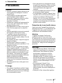
This symbol is intended to
alert the user to the presence
of uninsulated “dangerous
voltage” within the
product’s enclosure that may
be of sufficient magnitude to
constitute a risk of electric
shock to persons.
This symbol is intended to
alert the user to the presence
of important operating and
maintenance (servicing)
instructions in the literature
accompanying the
appliance.

3
GB
For the customers in Canada
This Class B digital apparatus complies with
Canadian ICES-003.
Voor de klanten in Nederland
Gooi de batterij niet weg
maar lever deze in als klein
chemisch afval (KCA).
The socket-outlet should be installed near
the equipment and be easily accessible.
CAUTION
RISK OF EXPLOSION IF BATTERY IS
REPLACED BY AN INCORRECT
TYPE.
DISPOSED OF USED BATTERIES
ACCORDING TO THE
INSTRUCTIONS.

Table of Contents
GB
4
Overview
Precautions .........................................6
Notes on Installation ..........................7
Unsuitable Installation .................7
Unsuitable Conditions ..................8
Usage in High Altitude .................8
Features ..............................................9
Location and Function of Controls .11
Top/Front/Left Side ....................11
Rear/Right Side/Bottom .............11
Control Panel ..............................12
Connector Panel .........................13
Remote Commander ...................14
Setting Up and Projecting
Installing the Projector .....................16
Connecting the Projector .................17
Connecting with a Computer .....17
Connecting with a VCR .............19
Projecting .........................................20
Turning Off the Power ...............22
Convenient Function
Selecting the Menu Language ..........23
Security Lock ...................................24
Other Functions ................................25
Switching from the Intelligent Auto-
setup Function to Manual
Adjustments ....................25
Controlling the Computer Using the
Supplied Remote
Commander (When Using
the USB Cable) ................25
Off & Go Function ......................25
Direct Power On/Off Function ...26
Effective Tools for Your
Presentation .....................26
Adjustments and Settings
Using the Menu
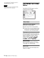
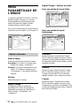
Using the MENU ..............................27
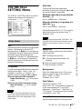
The PICTURE SETTING Menu ......29
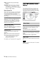
The INPUT SETTING Menu ...........30
The SET SETTING Menu ................32
The MENU SETTING Menu ...........34
The INSTALL SETTING Menu ......35
The INFORMATION Menu ............36
Maintenance
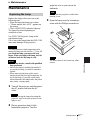
Maintenance .....................................37
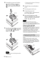
Replacing the Lamp ....................37
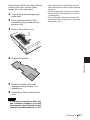
Cleaning the Air Filter ................38
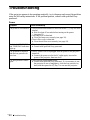
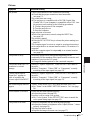
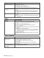
Troubleshooting ................................40
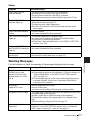
Warning Messages ......................43
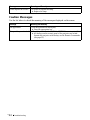
Caution Messages .......................44
Others
Specifications ...................................45
Installation Diagram .........................52
Floor Installation (Front
Projection) .......................52


GB
6 Precautions
B Overview
Precautions
On safety
• Check that the operating voltage of your
unit is identical with the voltage of your
local power supply.
• Should any liquid or solid object fall into
the cabinet, unplug the unit and have it
checked by qualified personnel before
operating it further.
• Unplug the unit from the wall outlet if it is
not to be used for several days.
• To disconnect the cord, pull it out by the
plug. Never pull the cord itself.
• The wall outlet should be near the unit and
easily accessible.
• The unit is not disconnected to the AC
power source (mains) as long as it is
connected to the wall outlet, even if the
unit itself has been turned off.
• Do not look into the lens while the lamp is
on.
• Do not place your hand or objects near the
ventilation holes. The air coming out is
hot.
• Be careful not to have your fingers caught
by the adjuster. The powered tilt adjuster
of this unit automatically extends when the
power is turned on, and is put away
automatically when the power is turned
off. Do not touch the unit while the
adjuster is in operation. Adjust the
powered tilt adjuster carefully after its
automatic operation is completed.
• Do not spread a cloth or paper under the
unit.
On illumination
• To obtain the best picture, the front of the
screen should not be exposed to direct
lighting or sunlight.
• Ceiling-mounted spot lighting is
recommended. Use a cover over
fluorescent lamps to avoid lowering the
contrast ratio.
• Cover any windows that face the screen
with opaque draperies.
• It is desirable to install the unit in a room
where floor and walls are not of light-
reflecting material. If the floor and walls
are of reflecting material, it is
recommended that the carpet and wall
paper be changed to a dark color.
On preventing internal heat build-
up
After you turn off the power with the I / 1
key, do not disconnect the unit from the wall
outlet while the cooling fan is still running.
Caution
The unit is equipped with ventilation holes
(intake) and ventilation holes (exhaust). Do
not block or place anything near these holes,
or internal heat build-up may occur, causing
picture degradation or damage to the
projector.
On cleaning
• To keep the cabinet looking new,
periodically clean it with a soft cloth.
Stubborn stains may be removed with a
cloth lightly dampened with a mild
detergent solution. Never use strong
solvents, such as thinner, benzene, or
abrasive cleansers, since these will
damage the cabinet.
• Avoid touching the lens. To remove dust
on the lens, use a soft dry cloth. Do not use
a damp cloth, detergent solution, or
thinner.
• Clean the filter at regular intervals.
On LCD data projector
• The LCD data projector is manufactured
using high-precision technology. You
may, however, see tiny black points and/or
bright points (red, blue, or green) that
continuously appear on the LCD data
projector. This is a normal result of the
manufacturing process and does not
indicate a malfunction.

7
GB
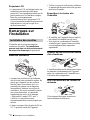
Notes on Installation
Overview
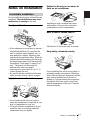
Notes on Installation
Do not install the projector in the following
situations. These installations may cause
malfunction or damage to the unit.
Poorly ventilated
• Allow adequate air circulation to prevent
internal heat build-up. Do not place the
unit on surfaces (rugs, blankets, etc.) or
near materials (curtains, draperies) that
may block the ventilation holes. When the
internal heat builds up due to the block-up,
the temperature sensor will function with
the message “High temp.! Lamp off in 1
min.” The power will be turned off
automatically after one minute.
• Leave space of more than 30 cm (11
7
/8
inches) around the unit.
• Be careful that the ventilation holes may
inhale tininess such as a piece of paper.
Highly heated and humid
• Avoid installing the unit in a location
where the temperature or humidity is very
high, or temperature is very low.
• To avoid moisture condensation, do not
install the unit in a location where the
temperature may rise rapidly.
Subject to direct cool or warm air
from an air-conditioner
Installing in such a location may cause
malfunction of the unit due to moisture
condensation or rise in temperature.
Near a heat or smoke sensor
Malfunction of the sensor may be caused.
Very dusty, extremely smoky
Avoid installing the unit in a very dusty or
extremely smoky environment. Otherwise,
the air filter will become obstructed, and this
may cause a malfunction of the unit or
damage it. Dust preventing the air passing
through the filter may cause a rise in the
internal temperature of the unit. Clean the
filter periodically.
Unsuitable Installation

GB
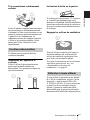
8 Notes on Installation
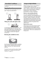
Do not use the projector under the following
conditions.
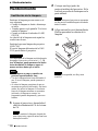
Toppling the unit
Avoid using as the unit topples over on its
side. It may cause malfunction.
Tilting the unit to the right or left
Avoid tilting the unit to an angle of 15°, and
avoid installing the unit in any way other
than placing on the floor or suspending from
the ceiling. Such installation may cause
color shading or shorten the lamp life
excessively.
Blocking the ventilation holes
Avoid using a thick-piled carpet or anything
that covers the ventilation holes (exhaust/
intake); otherwise, the internal heat may
build up.
For details on the ventilation holes (intake/
exhaust), see “Location and Function of
Controls” on page 11.
When using the projector at an altitude of
1,500 m or higher, turn on “High
Altitude Mode” in the INSTALL SETTING
menu. Failing to set this mode when using
the projector at high altitudes could have
adverse effects, such as reducing
the reliability of certain components.
Note on carrying the projector
The unit is manufactured using high-
precision technology. When transporting the
unit stored in the carrying case, do not drop
the unit or subject it to shock, as this may
cause damage. When storing the unit in the
carrying case, disconnect the AC power cord
and all other connecting cables, and store the
supplied accessories in a pocket of the
carrying case.
Note on the screen
When using a screen with an uneven surface,
stripes pattern may rarely appear on the
screen depending on the distance between
the screen and the projector or the zooming
magnifications. This is not a malfunction of
the projector.
Unsuitable Conditions Usage in High Altitude

9
GB
Features
Overview
Features
High brightness, high picture
quality
High brightness
Adopting Sony's unique new optical system
that incorporates newly developed LCD
panels provides a high-efficiency optical
system. It allows the 190 W UHP lamp to
give a light output of 3000ANSI lumen.
High picture quality
Three super-high-aperture 0.79-inch XGA
panels with approximately 790,000-pixel
micro-lens array, produce a resolution of
1024 × 768 dots (horizontal/vertical) for
RGB input, and 750 horizontal TV lines for
video input.
Quiet presentation environment
Low fan noise is achieved and offensive
sound to the ear is also reduced, allowing
you to run an optimum presentation even in
a quiet environment.
Easy setup and simple operation
Intelligent Auto-setup function
Simply press the power key, and the
projector automatically performs the setups
required before use. The projector opens the
lens protector, corrects the V Keystone,
detects a signal, and sets optimum
conditions for projection.
Powered zoom/focus equipped
The projector is equipped with a powered
zoom and powered focus lens, allowing you
to adjust the size and focus of an image with
the Remote Commander away from the
projector.
Short focal lens equipped
The projection distance is very short,
approximately 2.4 m (7.8 feet), when
projecting an 80-inch image, which allows
projection on a larger screen even in a
limited space.
Side Shot
The projector supports the Side Shot feature
(horizontal trapezoidal correction function),
enabling projection from the side of the
screen. Installation availability becomes
wider.
Off & Go feature
The cooling fan built in the projector will
work even after turning the power off and
the power cord is disconnected. This enables
you to move the projector to another location
immediately after turning it off.
Versatile installation capability
Capable of floor, ceiling or tilt
installation
In addition to the front floor or ceiling
installation, you can install the projector by
tilting it 90 degrees at the rear or 90 degrees
in front.
Direct Power On/Off function
The AC power of the entire system can be
directly turned on/off with a breaker or other
switch without pressing the power key on
the projector.
About this manual
The Illustrations indicated in this manual
may differ from those of this model in
specifications.

GB
10 Features
Security Functions
Security lock
This function makes it possible to project no
picture on the screen unless the required
password is entered when the projector is
turned on.
Panel key lock
This function locks all the operation keys on
the control panel of the projector, allowing
use of the keys on the Remote Commander.
This prevents the projector from operating
incorrectly.
..............................................................................................................................................................
• Windows is a registered trademark of Microsoft Corporation in the United States and/or other
countries.
• VGA, SVGA, XGA and SXGA are registered trademarks of the International Business
Machines Corporation, U.S.A.
• Kensington is a registered trademark of Kensington Technology Group.
• Macintosh is a registered trademark of Apple Computer, Inc.
• VESA is a registered trademark of Video Electronics Standard Association.
• Display Data Channel is a trademark of Video Electronics Standard Association.
• Side Shot is trademark of Sony Corporation.

11
GB
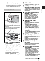
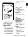
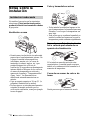
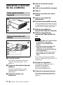
Location and Function of Controls
Overview
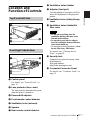
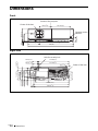
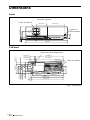
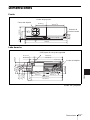
Location and
Function of Controls
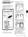
1 Control panel
For details, see “Control Panel” on
page 12.
2 Lens protector (lens cover)
The lens protector automatically opens
when the power is turned on.
3 Powered tilt adjuster
4 Front remote control detector
5 Ventilation holes (exhaust)
6 Speaker
7 Rear remote control detector
8 Ventilation holes (intake)
9 Adjuster (hind pad)
Turn the adjuster to the right or left for
minor tilt adjustment of the projected
picture.
q; Ventilation holes (intake)/Lamp
cover
qa Ventilation holes (intake)/Air
filter cover
• Do not place anything near the
ventilation holes as this may cause
internal heat build-up.
• Do not place your hand or objects
near the ventilation holes as this may
cause a heat build-up.
• To maintain optimal performance, clean
the air filter every 1000 hours.
For details, see “Cleaning the Air
Filter” on page 38.
qs Security lock
Connects to an optional security cable
(Kensington’s).
Web page address:
http://www.kensington.com/
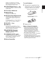
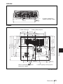
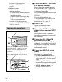
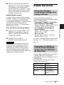
qd Connector/Connector Panel
For details, see “Connector Panel” on
page 13.
Top/Front/Left Side
Rear/Right Side/Bottom
1
2
3
4
6
5
7
8
q;
q
a
qs
qd
9
Notes

GB
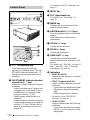
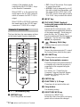
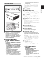
12 Location and Function of Controls
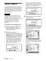
1 I / 1 (on/standby) key
Turns on the projector when the
projector is in standby mode. The ON/
STANDBY indicator around the I / 1
key lights in green when the power is
turned on.
2 ON/STANDBY indicator (located
around the
I / 1 key)
Lights up or flashes under the following
conditions:
– Lights in red when an AC power cord
is plugged into a wall outlet. Once in
standby mode, you can turn on the
projector with the I / 1 key.
– Lights in green when the power is
turned on.
– Flashes in green while the cooling fan
is running after the power is turned off
with the I / 1 key. The fan runs for
about 60 seconds after the power is
turned off.
For details on the I/1 indicators, see
page 22.
3 INPUT key
4 TILT adjustment key
For details, see “Projecting” on
page 20.
5 MENU key
Displays the on-screen menu. Press
again to clear the menu.
6 ENTER/Arrow(f/F/g/G) keys
Enter the settings of items in the menu
system.
Select the menu or make various
adjustments.
7 FOCUS +/– keys
Adjusts the picture focus.
8 ZOOM +/– keys
Adjusts the picture size.
9 SIDE SHOT +/– key
Adjusts the horizontal trapezoidal
distortion/H keystone correction of the
picture.
For details, see “Side Shot” on page 35
and ““Side Shot” and “V Keystone”
Adjustments” on page 56.
q; Indicators
• POWER SAVING
Lights when the projector is in power
saving mode.
• TEMP (Temperature)/FAN
Lights or flashes under the following
conditions:
– Lights when the temperature inside
the projector becomes unusually
high.
– Flashes when the fan is broken.
For details on the TEMP/FAN
indicator, see page 43.
• LAMP/COVER
Lights or flashes under the following
conditions:
– Lights when the lamp has reached
the end of its life or reaches a high
temperature.
Control Panel
FOCUS
Z
O
O
M
S
ID
E
S
H
O
T
P
O
W
E
R
ST
A
N
D
BY
T
E
M
P
/
F
A
N
LAMP/COVER
MENUINPUT
TILT
PUSH
ENTER
1
4
5
6
2
3
7
8
9
0

13
GB
Location and Function of Controls
Overview
– Flashes when the lamp cover or air
filter cover is not secured firmly.
For details on the LAMP/COVER and
TEMP/FAN indicator, see page 43.
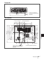
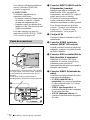
1 INPUT A connector (HD D-sub
15-pin, female)
Inputs a computer signal, video GBR
signal, component signal, or DTV signal
depending on equipment to be
connected.
Connects to the output connector of
equipment using the supplied cable or an
optional cable.
For details, see “Connecting with a
Computer” on page 17 and
“Connecting with a VCR” on page 19.
2 AC IN socket
Connects the supplied AC power cord.
3 AUDIO (stereo minijack)
connector (common INPUT A/B)
When listening to sound output from the
computer, connect to the audio output of
the computer.
4 USB connector (USB plug for
upstream, 4-pin)
Connect to the USB connector of a
computer. When you connect the
projector to the computer, you can
control the mouse function with the
supplied Remote Commander.
5 VIDEO IN (Video input)
connector
Connect to external video equipment
such as a VCR.
• S VIDEO (mini DIN 4-pin):
Connects to the S video output (Y/C
video output) of video equipment.
• VIDEO (phono type): Connects to
the composite video output of video
equipment.
• AUDIO (stereo minijack): Connects
to the audio output of the VCR.
6 INPUT B connector (HD D-sub
15-pin, female)
Connect to external equipment such as a
computer.
Connects to the monitor output of a
computer using an optional cable.
7 RS-232C connector (D-sub 9-
pin, female)
Connects to a computer to operate the
projector from the computer.
8 OUTPUT connector (HD D-sub
15-pin, female)
• MONITOR: Connect to the video
input connector of the monitor.
Outputs signals from the selected
channel and computer signals only
from among the signals from the
INPUT A or INPUT B.
• AUDIO (stereo minijack): Connects
to external active speakers. The
Connector Panel
VIDEOS VIDEO AUDIO
AUDIO
AUDIOMONITOR
INPUT A
VIDEO IN
OUTPUT
INPUT B
REMOTE RS-232C
PUSH SLIDE
1
2
VIDEO
S VIDEO
AUDIO
AUDIO
AUDIOMONITOR
INPUT A
INPUT A/B
VIDEO IN
OUTPUT
INPUT B
REMOTE
RS-232C
COVER
LOCK/UNLOCK
6
7
8
5
4
3
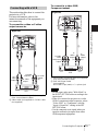
Open the cover when using the INPUT B or
VIDEO IN connector. To open the cover,
push the cover and slide it toward the right
until it locks.
To close the cover, press the cover to unlock
it and slide the cover toward the left.

GB
14 Location and Function of Controls
volume of the speakers can be
controlled by the VOLUME+/– keys
on the Remote Commander.
When INPUT A or B is selected, the
sound input to the AUDIO connector
which is common for INPUT A/B is
output.
When VIDEO or S VIDEO is selected,
the sound input to the AUDIO input
connector of VIDEO IN is output.
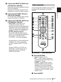
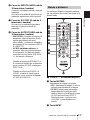
The keys that have the same names as those
on the control panel function identically.
1 I / 1 (on/standby) key
2 MUTING keys
Cut off the picture and sound.
• PIC: Cuts off the picture. Press again
to restore the picture.
• AUDIO: Press to temporarily cut off
the audio output from the speaker, and
the output on the AUDIO jack in the
OUTPUT section. Press again or press
VOLUME + key to restore the sound.
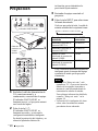
3 INPUT key
4 TILT/KEYSTONE (Vertical/
horizontal trapezoidal distortion
correction) key
Adjusts the tilt of the projector, or the
horizonal/vertical trapezoidal distortion
of the image manually. Each time you
press this key, the Tilt menu, the V
Keystone menus and Side Shot menu are
displayed. Use the arrow keys (M/m/
</,) for adjustment.
5 (Memory Stick) key
This key does not work in this unit.
6 FREEZE key
Freezes the picture projected. To cancel
the frozen picture, press the key again.
7 AIR SHOT key
This key does not work in this unit.
8 Keys that emulate a mouse
These keys function as mouse buttons of
a computer only when the projector is
connected to the computer using the
USB cable.
For details, see “Controlling the
Computer Using the Supplied Remote
Commander (When Using the USB
Cable)” on page 25.
9 ENTER key
q; FUNCTION 1, 2, 3 keys
These keys do not work in this unit.
qa Strap holder
For attaching a strap.
qs RESET/ESCAPE key
Functions as a RESET key.
Resets the value of an item to its factory
preset value or returns the enlarged
Remote Commander
MUTING
PIC
AUDIO
LENS
APA
AIR SHOT
INPUT
TILT/KEYSTONE
PJ NETWORK
ON
COMMAND
OFF
VOLUME
ENTER
FUNCTION
RM-PJM15
D ZOOM
CLICK
RESET/
ESCAPE
MENU/
TAB
R
1
2
3
FREEZE
PROJECTOR
RM-PJM17
1
2
3
4
8
a
8
b
8
c
9
q;
wa
w;
ql
qk
qj
qh
qg
qf
qd
qs
qa
6
7
5

15
GB
Location and Function of Controls
Overview
image to its original size. This key
functions when the menu or a setting
item is displayed on the screen.
qd D ZOOM (Digital Zoom) +/– key
Enlarges the image at a desired location
on the screen.
qf Arrow keys (M/m/</,)
qg MENU/TAB key
Functions as a MENU key.
qh APA (Auto Pixel Alignment) key
Automatically adjusts a picture to its
clearest while a signal is input from a
computer.
For details on APA, see “Smart APA” in
the SET SETTING menu on page 32.
qj VOLUME +/– keys
qk LENS key
Each time you press this key, Focus
adjustment menu and Zoom adjustment
menu are displayed alternately.
ql PJ/NETWORK (Projector/
Network) selector switch
Normally, set to “PJ”.
w; COMMAND ON/OFF switch
When this switch is set to OFF, no key
on the Remote Commander function.
This saves battery power.
wa Infrared transmitter
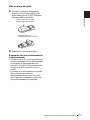
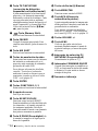
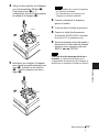
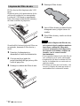
To install batteries
1 Push and slide to open the lid, then
install the two size AA (R6) batteries
(supplied) with the correct polarity.
2 Replace the lid.
Notes on Remote Commander
• Make sure that nothing obstructs the
infrared beam between the Remote
Commander and the remote control
detector on the projector. Direct the
Remote Commander toward the front or
rear remote control detector.
• The operation range is limited. The shorter
the distance between the Remote
Commander and the projector is, the wider
the angle within which the commander can
control the projector becomes.
Be sure to install the battery
from the
# side.
While pressing the lid, slide it.

GB
16 Installing the Projector
B Setting Up and Projecting
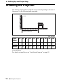
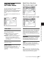
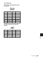
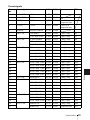
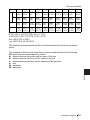
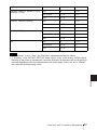
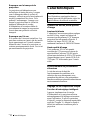
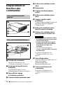
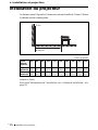
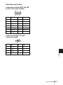
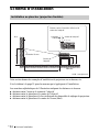
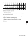
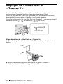
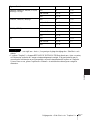
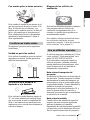
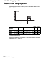
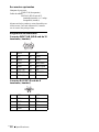
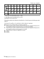
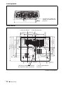
Installing the Projector
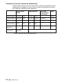
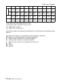
The distance between the lens and the screen varies depending on the size of
the screen. Use the following table as a guide.
There may be a slight difference between the actual value and the design value shown
in the table above.
For details on installation, see “Installation Diagram” on page 52.
Unit: m (feet)
Screen
size
(inches)
40 60 80 100 120 150 180 200 250 300
Minimum
Distance
1.2
(3.9)
1.8
(5.9)
2.4
(7.9)
3.0
(9.8)
3.6
(11.8)
4.5
(14.8)
5.4
(17.7)
6.0
(19.7)
7.5
(24.6)
9.0
(29.5)
Maximum
Distance
1.4
(4.6)
2.0
(6.6)
2.7
(8.9)
3.4
(11.2)
4.1
(13.5)
5.2
(17.1)
6.2
(20.3)
6.9
(22.6)
8.7
(28.5)
10.4
(34.1)
Distance between the screen and
the center of the lens
Screen

17
GB
Connecting the Projector
Setting Up and Projecting
Connecting the
Projector
When you connect the projector,
make sure to:
• Turn off all equipment before making any
connections.
• Use the proper cables for each connection.
• Insert the cable plugs firmly; loose
connections may increase noise and
reduce performance of picture signals.
When pulling out a cable, be sure to pull it
out from the plug, not the cable itself.
To connect the projector, refer to
the illustrations on the next and the
following pages.
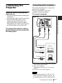
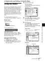
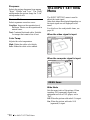
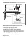
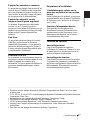
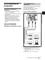
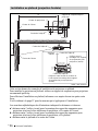
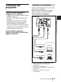
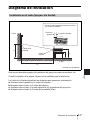
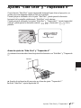
This section describes how to connect the
projector to a computer.
For more information, refer to the
computer’s instruction manual.
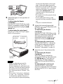
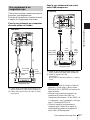
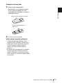
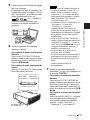
To connect a computer
1 Stereo audio connecting cable (not supplied)
(Use a no-resistance cable.)
2 USB cable (supplied)
(Connect the USB cable to use a wireless
mouse.)
3 HD D-sub 15-pin cable (supplied)
• The projector accepts VGA, SVGA, XGA,
SXGA and SXGA+ signals. However, we
recommend that you set the output mode of
Connecting with a Computer
Notes
VIDEOS VIDEO AUDIO
AUDIO
AUDIOMONITOR
INPUT A
VIDEO IN
OUTPUT
INPUT B
REMOTE RS-232C
123
to USB connector
Right side
to monitor output
Computer
to audio output

GB
18 Connecting the Projector
your computer to XGA mode for the external
monitor.
• If you set your computer, such as a notebook
type, to output the signal to both your
computer’s display and the external monitor,
the picture of the external monitor may not
appear properly. Set your computer to output
the signal to only the external monitor.
For details, refer to the computer’s
operating instructions supplied with your
computer.
On the USB function
When connecting the projector to a
computer by using the USB cable for the
first time, the computer recognizes the
USB
hu
man interface device (wireless mouse
function) automatically.
Recommended operating
environment
When you use the USB function, connect the
USB cable as illustrated above. The USB
function can be used on a computer loaded
with Windows 98, Windows 98 SE,
Windows ME, Windows 2000 or Windows
XP preinstall models.
• Your computer may not start correctly
when connected to the projector via the
USB cable. In this case, disconnect the
USB cable, restart the computer, then
connect the computer to the projector
using the USB cable.
• This projector is not guaranteed for
suspend, standby mode. When you use the
projector in suspend, standby mode,
disconnect the projector from the USB
port on the computer.
• Operations are not guaranteed for all the
recommended computer environments.
To connect a Macintosh computer
To connect a Macintosh computer equipped
with video output connector of a type having
two rows of pins, use a commercially
available plug adaptor. When you connect a
USB capable Macintosh computer using the
USB cable to the projector, wireless mouse
functions become available.
Notes

19
GB
Connecting the Projector
Setting Up and Projecting
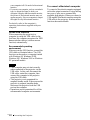
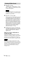
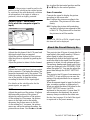
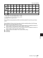
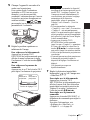
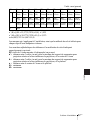
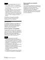
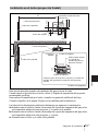
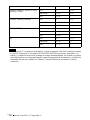
This section describes how to connect the
projector to a VCR.
For more information, refer to the
instruction manuals of the equipment you
are connecting.
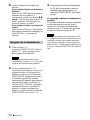
To connect to a video or S video
output connector
1 Stereo audio connecting cable (not supplied)
(Use a no-resistance cable.)
2 Video cable (not supplied) or S-Video cable
(not supplied)
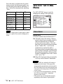
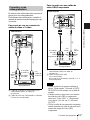
To connect to a video GBR/
Component output
1 Stereo audio connecting cable (not supplied)
(Use a no-resistance cable.)
2 SMF-402 Signal Cable
(not supplied)
HD D-sub 15-pin (male) ↔ 3 × phono jack
• Set the aspect ratio using “Wide Mode” in
the INPUT SETTING menu according to the
input signal.
• When you connect the projector to a video
GBR or component output connector, select
“Video GBR” or “Component” with the
“Input-A Signal Sel.” setting in the SET
SETTING menu.
• Use the composite sync signal when you
input the external sync signal from video
GBR/component equipment.
Connecting with a VCR
VIDEOS VIDEO AUDIO
AUDIO
AUDIOMONITOR
INPUT A
VIDEO IN
OUTPUT
INPUT B
REMOTE RS-232C
21
VCR
to S
video
output
Right side
to audio
output
(R)
to video
output
to audio
output (L)
Notes
VIDEOS VIDEO AUDIO
AUDIO
AUDIOMONITOR
INPUT A
VIDEO IN
OUTPUT
INPUT B
REMOTE RS-232C
21
Right side
to
audio
output
(R)
VCR
to video
GBR/
component
output
to
audio
output
(L)

GB
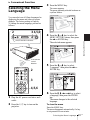
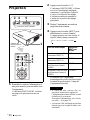
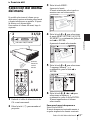
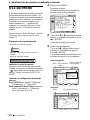
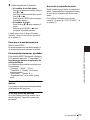
20 Projecting
Projecting
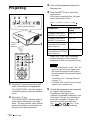
1 Plug the AC power cord into a wall
outlet, then connect all equipment.
The ON/STANDBY indicator lights in
red and the projector goes into standby
mode.
2 Press the I / 1 key.
The ON/STANDBY indicator lights in
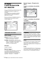
green and the Intelligent Auto-setup
starts. The lens protector opens, and the
powered tilt adjuster rises and stops at
the previously adjusted position.
3 Turn on the equipment connected to
the projector.
4 Press the INPUT key to select the
input source.
Each time you press the key, the input
signal switches as follows:
Smart APA (Auto Pixel Alignment)
adjusts the picture of the connected
equipment so that it is projected clearly.
• If “Auto Input Search” is set to “On,” the
projector searches for the signals from
the connected equipment and displays
the input channel where the input signals
are found.
For details, see “Auto Input Search”
on page 33.
• The Smart APA is effective for the input
signal from a computer only.
5 Switch the equipment to be connected
to output to the projector.
Depending on the type of your
computer, for example a notebook, or an
all-in-one LCD type, you may have to
switch the computer to output to the
projector by pressing certain keys
(e.g., , etc.), or by
changing your computer’s settings.
MENUINPUT
TILT
PUSH
ENTER
MUTING
PIC
AUDIO
LENS
APA
AIR SHOT
INPUT
TILT/KEYSTONE
PJ NETWORK
ON
COMMAND
OFF
VOLUME
MENU/
TAB
FREEZE
2
2
4
5
4
5
6
1
ON/STANDBY indicators
Rear remote
control
detector
To input from Press INPUT to
display
Computer connected to
the INPUT A connector
INPUT-A
Computer connected to
the INPUT B connector
INPUT-B
Video equipment
connected to the VIDEO
input connector
VIDEO
Video equipment
connected to the S VIDEO
input connector
S-VIDEO
Notes
t
INPUT-A
t
INPUT-B
t
VIDEO
t
S-VIDEO
VGA
LCD
//
,
La page est en cours de chargement...
La page est en cours de chargement...
La page est en cours de chargement...
La page est en cours de chargement...
La page est en cours de chargement...
La page est en cours de chargement...
La page est en cours de chargement...
La page est en cours de chargement...
La page est en cours de chargement...
La page est en cours de chargement...
La page est en cours de chargement...
La page est en cours de chargement...
La page est en cours de chargement...
La page est en cours de chargement...
La page est en cours de chargement...
La page est en cours de chargement...
La page est en cours de chargement...
La page est en cours de chargement...
La page est en cours de chargement...
La page est en cours de chargement...
La page est en cours de chargement...
La page est en cours de chargement...
La page est en cours de chargement...
La page est en cours de chargement...
La page est en cours de chargement...
La page est en cours de chargement...
La page est en cours de chargement...
La page est en cours de chargement...
La page est en cours de chargement...
La page est en cours de chargement...
La page est en cours de chargement...
La page est en cours de chargement...
La page est en cours de chargement...
La page est en cours de chargement...
La page est en cours de chargement...
La page est en cours de chargement...
La page est en cours de chargement...
La page est en cours de chargement...
La page est en cours de chargement...
La page est en cours de chargement...
La page est en cours de chargement...
La page est en cours de chargement...
La page est en cours de chargement...
La page est en cours de chargement...
La page est en cours de chargement...
La page est en cours de chargement...
La page est en cours de chargement...
La page est en cours de chargement...
La page est en cours de chargement...
La page est en cours de chargement...
La page est en cours de chargement...
La page est en cours de chargement...
La page est en cours de chargement...
La page est en cours de chargement...
La page est en cours de chargement...
La page est en cours de chargement...
La page est en cours de chargement...
La page est en cours de chargement...
La page est en cours de chargement...
La page est en cours de chargement...
La page est en cours de chargement...
La page est en cours de chargement...
La page est en cours de chargement...
La page est en cours de chargement...
La page est en cours de chargement...
La page est en cours de chargement...
La page est en cours de chargement...
La page est en cours de chargement...
La page est en cours de chargement...
La page est en cours de chargement...
La page est en cours de chargement...
La page est en cours de chargement...
La page est en cours de chargement...
La page est en cours de chargement...
La page est en cours de chargement...
La page est en cours de chargement...
La page est en cours de chargement...
La page est en cours de chargement...
La page est en cours de chargement...
La page est en cours de chargement...
La page est en cours de chargement...
La page est en cours de chargement...
La page est en cours de chargement...
La page est en cours de chargement...
La page est en cours de chargement...
La page est en cours de chargement...
La page est en cours de chargement...
La page est en cours de chargement...
La page est en cours de chargement...
La page est en cours de chargement...
La page est en cours de chargement...
La page est en cours de chargement...
La page est en cours de chargement...
La page est en cours de chargement...
La page est en cours de chargement...
La page est en cours de chargement...
La page est en cours de chargement...
La page est en cours de chargement...
La page est en cours de chargement...
La page est en cours de chargement...
La page est en cours de chargement...
La page est en cours de chargement...
La page est en cours de chargement...
La page est en cours de chargement...
La page est en cours de chargement...
La page est en cours de chargement...
La page est en cours de chargement...
La page est en cours de chargement...
La page est en cours de chargement...
La page est en cours de chargement...
La page est en cours de chargement...
La page est en cours de chargement...
La page est en cours de chargement...
La page est en cours de chargement...
La page est en cours de chargement...
La page est en cours de chargement...
La page est en cours de chargement...
La page est en cours de chargement...
La page est en cours de chargement...
La page est en cours de chargement...
La page est en cours de chargement...
La page est en cours de chargement...
La page est en cours de chargement...
La page est en cours de chargement...
La page est en cours de chargement...
La page est en cours de chargement...
La page est en cours de chargement...
La page est en cours de chargement...
La page est en cours de chargement...
La page est en cours de chargement...
La page est en cours de chargement...
La page est en cours de chargement...
La page est en cours de chargement...
La page est en cours de chargement...
La page est en cours de chargement...
La page est en cours de chargement...
La page est en cours de chargement...
La page est en cours de chargement...
La page est en cours de chargement...
La page est en cours de chargement...
La page est en cours de chargement...
La page est en cours de chargement...
La page est en cours de chargement...
La page est en cours de chargement...
La page est en cours de chargement...
La page est en cours de chargement...
La page est en cours de chargement...
La page est en cours de chargement...
La page est en cours de chargement...
La page est en cours de chargement...
La page est en cours de chargement...
La page est en cours de chargement...
La page est en cours de chargement...
La page est en cours de chargement...
La page est en cours de chargement...
La page est en cours de chargement...
La page est en cours de chargement...
La page est en cours de chargement...
La page est en cours de chargement...
La page est en cours de chargement...
La page est en cours de chargement...
La page est en cours de chargement...
La page est en cours de chargement...
La page est en cours de chargement...
-
 1
1
-
 2
2
-
 3
3
-
 4
4
-
 5
5
-
 6
6
-
 7
7
-
 8
8
-
 9
9
-
 10
10
-
 11
11
-
 12
12
-
 13
13
-
 14
14
-
 15
15
-
 16
16
-
 17
17
-
 18
18
-
 19
19
-
 20
20
-
 21
21
-
 22
22
-
 23
23
-
 24
24
-
 25
25
-
 26
26
-
 27
27
-
 28
28
-
 29
29
-
 30
30
-
 31
31
-
 32
32
-
 33
33
-
 34
34
-
 35
35
-
 36
36
-
 37
37
-
 38
38
-
 39
39
-
 40
40
-
 41
41
-
 42
42
-
 43
43
-
 44
44
-
 45
45
-
 46
46
-
 47
47
-
 48
48
-
 49
49
-
 50
50
-
 51
51
-
 52
52
-
 53
53
-
 54
54
-
 55
55
-
 56
56
-
 57
57
-
 58
58
-
 59
59
-
 60
60
-
 61
61
-
 62
62
-
 63
63
-
 64
64
-
 65
65
-
 66
66
-
 67
67
-
 68
68
-
 69
69
-
 70
70
-
 71
71
-
 72
72
-
 73
73
-
 74
74
-
 75
75
-
 76
76
-
 77
77
-
 78
78
-
 79
79
-
 80
80
-
 81
81
-
 82
82
-
 83
83
-
 84
84
-
 85
85
-
 86
86
-
 87
87
-
 88
88
-
 89
89
-
 90
90
-
 91
91
-
 92
92
-
 93
93
-
 94
94
-
 95
95
-
 96
96
-
 97
97
-
 98
98
-
 99
99
-
 100
100
-
 101
101
-
 102
102
-
 103
103
-
 104
104
-
 105
105
-
 106
106
-
 107
107
-
 108
108
-
 109
109
-
 110
110
-
 111
111
-
 112
112
-
 113
113
-
 114
114
-
 115
115
-
 116
116
-
 117
117
-
 118
118
-
 119
119
-
 120
120
-
 121
121
-
 122
122
-
 123
123
-
 124
124
-
 125
125
-
 126
126
-
 127
127
-
 128
128
-
 129
129
-
 130
130
-
 131
131
-
 132
132
-
 133
133
-
 134
134
-
 135
135
-
 136
136
-
 137
137
-
 138
138
-
 139
139
-
 140
140
-
 141
141
-
 142
142
-
 143
143
-
 144
144
-
 145
145
-
 146
146
-
 147
147
-
 148
148
-
 149
149
-
 150
150
-
 151
151
-
 152
152
-
 153
153
-
 154
154
-
 155
155
-
 156
156
-
 157
157
-
 158
158
-
 159
159
-
 160
160
-
 161
161
-
 162
162
-
 163
163
-
 164
164
-
 165
165
-
 166
166
-
 167
167
-
 168
168
-
 169
169
-
 170
170
-
 171
171
-
 172
172
-
 173
173
-
 174
174
-
 175
175
-
 176
176
-
 177
177
-
 178
178
-
 179
179
-
 180
180
-
 181
181
-
 182
182
-
 183
183
-
 184
184


Sony VPL-CX80 Manuel utilisateur
- Catégorie
- Téléviseurs
- Taper
- Manuel utilisateur
dans d''autres langues
- English: Sony VPL-CX80 User manual
- español: Sony VPL-CX80 Manual de usuario
