Bosch RGM8058UC Guide d'installation
- Catégorie
- Cuisinières
- Taper
- Guide d'installation
Ce manuel convient également à

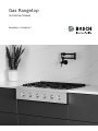
Installation Manual
Gas Rangetop
RGM8058UC, RGM8658UC

2
Table of Contents
Installation instructions
9 Safety Definitions ..................................................... 2
IMPORTANT SAFETY INSTRUCTIONS ........................ 3
Appliance Handling Safety ................................................. 4
Safety Codes and Standards ............................................. 4
Electric Safety ....................................................................... 4
Gas Safety ............................................................................. 4
Related Equipment Safety .................................................. 5
Conversion to Propane Gas ............................................... 5
High Altitude Installation ..................................................... 5
Before You Begin .......................................................... 6
Tools and Parts Needed ..................................................... 6
Parts Included ....................................................................... 6
Removing Packaging .......................................................... 6
General Information ............................................................. 7
Cabinet Requirements ......................................................... 7
Countertop Requirements .................................................. 7
Technical Data ...................................................................... 8
Installation Checklist ............................................................ 8
Installation Procedure .................................................. 8
Prepare Installation Space ................................................. 8
Connect Gas Supply ........................................................... 9
Install Appliance ................................................................ 10
Connect Electrical Supply ............................................... 10
Burner Cap Placement ..................................................... 11
Check the Installation ....................................................... 12
Test for Gas Leaks ............................................................ 12
Conversion to Propane Gas (LPG) ............................ 13
Technical Service ........................................................ 16
How to Obtain Warranty Service .................................... 16
Wiring Diagram for RGM8658UC ............................... 17
Wiring Diagram for RGM8058UC ............................... 18
9 Safety Definitions
Safety Defi nitions
9 WARNING
This indicates that death or serious injuries may
occur as a result of non-observance of this warning.
9 CAUTION
This indicates that minor or moderate injuries may
occur as a result of non-observance of this warning.
NOTICE: This indicates that damage to the appliance or
property may occur as a result of non-compliance with
this advisory.
Note: This alerts you to important information and/or
tips.

3
9 IMPORTANT SAFETY INSTRUCTIONS
READ AND SAVE THESE INSTRUCTIONS
IMPORTANT SAFET Y I NS T RUCT I ONSRE AD AND SAVE THESE INSTRUCTIONS
Gas Appliance Safety
²
'RQRWVWRUHRUXVHJDVROLQHRURWKHUIODPPDEOH
YDSRUVDQGOLTXLGVLQWKHYLFLQLW\RIWKLVRUDQ\
RWKHUDSSOLDQFH
²
:+$772'2,)<2860(//*$6
'RQRWWU\WROLJKWDQ\DSSOLDQFH
'RQRWWRXFKDQ\HOHFWULFDOVZLWFK
'RQRWXVHDQ\SKRQHLQ\RXUEXLOGLQJ
,PPHGLDWHO\FDOO\RXUJDVVXSSOLHUIURPD
QHLJKERU·VSKRQH)ROORZWKHJDVVXSSOLHU·V
LQVWUXFWLRQV
,I\RXFDQQRWUHDFK\RXUJDVVXSSOLHUFDOO
WKHILUHGHSDUWPHQW
²
,QVWDOODWLRQDQGVHUYLFHPXVWEHSHUIRUPHG
E\DTXDOLILHGLQVWDOOHUVHUYLFHDJHQF\RUWKH
JDVVXSSOLHU
:$51,1*,IWKHLQIRUPDWLRQLQWKHVHLQVWUXFWLRQV
LVQRWIROORZHGH[DFWO\DILUHRUH[SORVLRQPD\
UHVXOWFDXVLQJSURSHUW\GDPDJHSHUVRQDOLQMXU\
RUGHDWK

9 IMPORTANT SAFETY INSTRUCTIONS
READ AND SAVE THESE INSTRUCTIONS
4
IMPORTANT: THE APPLIANCE MUST BE INSTALLED BY
A QUALIFIED INSTALLER.
INSTALLER: LEAVE THESE INSTRUCTIONS WITH THE
APPLIANCE AFTER INSTALLATION IS COMPLETE.
IMPORTANT: SAVE FOR THE LOCAL INSPECTOR’S
USE.
WARNING
If the information in this manual is not followed exactly,
fire or shock may result causing property damage or
personal injury.
WARNING
Do not repair, replace or remove any part of the
appliance unless specifically recommended in the
manuals. Improper installation, service or maintenance
can cause injury or property damage. Refer to this
manual for guidance. All other servicing should be done
by an authorized servicer.
Improper installation is not covered by the warranty.
Appliance Handling Safety
Safety Codes and Standards
This appliance complies with one or more of the
following Standards:
ANSI Z21.1/ CSA 1.1Household Cooking Gas
Appliances
It is the responsibility of the owner and the installer to
determine if additional requirements and/or standards
apply to specific installations.
Installation must conform with local codes or, in the
absence of local codes, with the National Fuel Gas
Code, ANSI Z223.1/NFPA 54or, in Canada, the Natural
Gas and Propane Installation Code, CSA B149.1.
The appliance must be electrically grounded in
accordance with local codes or, in the absence of local
codes, with the National Electrical Code, NFPA 70latest
edition or, in Canada, the Canadian Electric Code, CSA
C22.1-02.
Electric Safety
WARNING
Before you plug in an electrical cord or turn on power
supply, make sure all controls are in the OFF position.
Be sure your appliance is properly installed and
grounded by a qualified technician. Installation, electrical
connections and grounding must comply with all
applicable codes.
Before installing, turn power OFF at the service panel.
Lock service panel to prevent power from being turned
ON accidentally.
For appliances equipped with a cord and plug, do not
cut or remove the ground prong. It must be plugged into
a matching grounding type receptacle to avoid electrical
shock. If there is any doubt as to whether the wall
receptacle is properly grounded, the customer should
have it checked by a qualified electrician.
Do not use an extension cord.
Do not use an adapter.
If required by the National Electrical Code (or Canadian
Electrical Code), this appliance must be installed on a
separate branch circuit.
The circuit breaker should have a contact separation of
at least 3mm on all poles.
Installer – show the owner the location of the circuit
breaker or fuse. Mark it for easy reference.
Refer to rating label for more information. See "How to
Obtain Warranty Service" under "Technical Service" for
rating label location.
Gas Safety
Install a gas shutoff valve near the appliance. It must be
easily accessible in an emergency.
Leak testing must be conducted by the installer
according to the instructions in this manual.
The appliance and its individual shutoff valve must be
disconnected from the gas supply piping system during
any pressure testing at pressures in excess of ½ psi
(3.5kPa).
The appliance must be isolated from the gas supply
piping system by closing its individual manual shutoff
valve during any pressure testing of the gas supply
piping system at test pressures equal to or less than
½ psi (3.5 kPa).
The minimum supply pressure must be 1" water column
above the manifold pressure printed on the rating label.
The maximum supply pressure must not exceed
14.0inches water column (34.9 Millibars).
IMPORTANT SAFETY NOTICE: Burning gas cooking fuel
generates some by-products which are on the list of
substances which are known by the State of California to
cause cancer or reproductive harm. To minimize
exposure to these substances, always operate this unit
according to the instructions contained in this booklet
and provide good ventilation.
Hidden surfaces may have sharp edges.
Use caution when reaching behind or
under appliance.

5
9 IMPORTANT SAFETY INSTRUCTIONS
READ AND SAVE THESE INSTRUCTIONS
Proposition 65Warning:
This product may contain a chemical known to the State
of California, which can cause cancer or reproductive
harm. Therefore, the packaging of your product may
bear the following label as required by California:
Related Equipment Safety
The appliance should only be used if installed by a
qualified technician in accordance with these installation
instructions and all applicable regulations and codes.
The manufacturer is not responsible for damages
resulting from incorrect installation.
Remove all tape and packaging before using the
appliance. Destroy the packaging after unpacking the
appliance. Never allow children to play with packaging
material.
Never modify or alter the construction of the appliance.
For example, do not remove leveling legs, panels, wire
covers or anti-tip brackets/screws.
To eliminate the risk of burns or fire by reaching over
heated surface units, cabinet storage space located
above the surface units should be avoided. If cabinet
storage is to be provided, the risk can be reduced by
installing a hood that projects horizontally a minimum of
5inches (127 mm) beyond the bottom of the cabinet.
Verify that cabinets above the cooktop are a maximum of
13" (330 mm) deep.
When installing a cooktop over a single oven, be sure to
follow both the oven’s and cooktop’s installation
manuals.
Ventilation Recommendations
We strongly recommend the installation of a ventilation
hood above this appliance. The hood must be installed
according to instructions furnished with the hood.
CAUTION
The appliance should not be installed with a ventilation
system that blows air downward toward the burners. This
type of ventilation system may cause ignition and
combustion problems with the gas cooking appliance
resulting in personal injury or unintended operation.
Conversion to Propane Gas
WARNING
Personal injury or death from electrical shock may occur
if the appliance is not installed by a qualified installer or
electrician.
Any additions, changes or conversions required in order
for this appliance to satisfactorily meet the application
needs must be made by a qualified technician.
High Altitude Installation
This appliance has been tested for operation up to an
altitude of 10,000ft (3,048m) elevation above sea level.
If desired, for altitudes above 2,000 ft (610 m) elevation
above sea level, adjustments may be made. Burners
should be checked at the lowest setting, if the flame is
not stable the simmer should be increased until the
flame is stable. This can be done by adjusting the
bypass screw in the valve. If flame performance is
satisfactory, adjustment will not be required. It is required
that a Certified Professional make the high altitude
adjustments during installation.
&DQFHUDQG5HSURGXFWLYH+DUPZZZ3:DUQLQJVFDJRY
67$7(2)&$/,)251,$352326,7,21:$51,1*
:$51,1*

6
Before You Begin
Before You Begin
Tools and Parts Needed
▯ Phillips head screwdriver
▯ Slotted screwdriver 1/8" (3,5 mm)
▯ Adjustable wrench
▯ Tongue and groove pliers
▯ Pencil
▯ Tape measure
Note: Additional materials may be necessary for
installation in solid surface countertops. Contact the
countertop manufacturer.
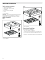
Parts Included
30”:
* Attached to the appliance.
36”:
* Attached to the appliance.
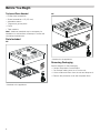
Removing Packaging
See the diagram on the packaging.
▯ If straps are present, cut the straps.
▯ Cut the tape making sure not to cut the unit.
▯ Lift the cardboard carton from the unit and dispose of.
▯ Remove the protective cover and the plastic films.

7
General Information
30”:
36”:
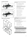
Cabinet Requirements
The minimum spaces that must be maintained when
installing the gas cooktop shall be:
* Minimum distance is 12" (305 mm), but the total
distance, left plus right, must be minimum 40"
(1016 mm).
Gas supply line and grounded outlet
X = Gas Supply Line
Y = Grounded Outlet
The positions of the gas supply line and the grounded
outlet should be:
Countertop Requirements
9 WARNING
To reduce the risk of ignition of surrounding
combustible materials, install at least 20" (508 mm)
from both sidewalls. Minimum distance is 12"
(305 mm), but the total distance, left plus right, must
be minimum 40" (1016mm).
The countertop must be level and horizontal. The stability
of the countertop must be maintained after the cut-out
has been made.
$
%
'
*
)
(
,
.
-
1
1
2
2
2
0
0
&
+
/
/
/
A 30": minimum 30" (762 mm)
36": minimum 36" (914 mm)
B minimum 20" (508 mm)*
C minimum 30" (762 mm) clearance between
the top of the cooking surface and the
bottom of the unprotected wood or metal
cabinet
D 30": minimum 30" (762 mm)
36": minimum 36" (914 mm)
E minimum 24" (610 mm)
F maximum 13" (330 mm)
G minimum 20" (508 mm)*
H 73/8" (187 mm)
I minimum 4" (102 mm)
J minimum 12" (305 mm)
K minimum 0" (0 mm)
L 8-12" (203-305 mm)
M 2-4" (51-101 mm)
N 24-28" (610-711 mm)
O 24-28" (610-711 mm)

8
Technical Data
30” (4burners):
36” (6burners):
Installation Checklist
Please refer to the pages following for complete
installation instructions. Use this checklist to verify that
you have completed each step of the installation
process. This can help you avoid mistakes.
Installation Procedure
Installation Procedure
An air curtain or other overhead range hood, which
operates by blowing a downward airflow onto a range,
shall not be used in conjunction with the gas range
unless the hood and range have been designed and
tested in accordance with ANSI Z21.1and listed by an
independent testing laboratory for combination use.
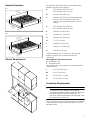
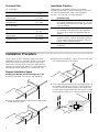
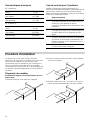
Prepare Installation Space
Prepare Installati on Space
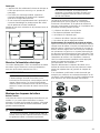
Installing the Bracket with Recess Depth up to 24”
1.
Measure the width of the slot for the appliance.
2.
Divide the measurement in two and trace the midline
on the furniture’s floor.
3.
Measure from the wall 21” (about 534 mm) and trace
a line perpendicular to the midline.
4.
Put the bracket approximately as in the figure below, in
the middle of the two lines (since it’s not necessary to
be more precise because the slot in the range top’s
floor provides enough clearance) and trace the center
of the bracket’s holes or fix it directly with the screws.
Total connected load, electric 0.001 A
0.1 W
Total connected load, gas
(natural gas)
47,000BTU/h
(13.7 kW)
Total connected load, gas
(propane gas)
47,000BTU/h
(13.7 kW)
Total connected load, electric 0.001 A
0.1 W
Total connected load, gas
(natural gas)
77,000BTU/h
(22.5 kW)
Total connected load, gas
(propane gas)
77,000BTU/h
(22.5 kW)
è
Installation step
Before installing the cooktop, be sure to verify
the cabinet dimensions are correct for your unit
and that the required electrical and gas connec-
tions are present.
Before installing the cooktop, make sure that
any opening in the wall behind the appliance
and in the floor under the appliance shall be
sealed.
Refer to the installation manual for content
regarding Safety, Cabinet Dimensions, Remov-
ing Packaging, Electrical Installation, Gas Con-
nection, and Customer Service.
Plug the cooktop into a properly configured
receptacle.

9
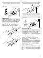
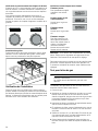
Installing the Bracket with Recess Depth over 24”
If the depth is more than 24” you can choose to install
the range top against the wall as in the previous
procedure and let the control panel go inside the
furniture. Or you can decide to align the control panel
with the rear side of the furniture and have a clearance
on the back part between the appliance and the wall, so:
1.
Measure the width of the slot for the appliance.
2.
Divide the measurement in two and trace the midline
on the furniture’s floor.
3.
Measure from front side of the furniture 3” (about
76 mm) and trace a line perpendicular to the midline.
4.
Put the bracket approximately as in the figure below, in
the middle of the two lines (since it’s not necessary to
be more precise because the slot in the range top’s
floor provides enough clearance) and trace the center
of the bracket’s holes or fix it directly with the screws.
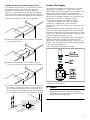
Connect Gas Supply
The appliance is shipped from the factory for use with
natural gas at a pressure of 5" of the water column.
When checking for proper operation of the regulator, the
inlet pressure must be at least 1" greater than the
operating (manifold) pressure above. When used with
natural gas, the pressure supplied to the regulator must
be between 6" and 10,5" of the water column.
To convert the appliance to propane gas see
“Conversion to propane gas (LPG)”. A qualified
technician or installer must do the conversion.
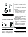
The gas inlet to the unit is located at the right rear of the
appliance.
Install the pressure regulator (supplied with unit) to gas
inlet. Postion the gasket (supplied with unit) in between
the inlet and the regulator. Position the regulator to have
it cap D (~ Page 15) easily accessible. Turn the nut on
gas inlet to hand tighten plus 1/3 turn.
Install the gas pipe to the regulator using Teflon tape or
pipe-joint compound (resistant to propane gas and
natural gas). Turn to hand tighten plus 1/3turn. Do not
exceed 1 turn for alignment, to prevent possible damage
to the gas pressure regulator.
Check inlet fittings and regulator for leaks.
* Attached to the appliance.
9 WARNING
Do not attempt any adjustment of the pressure
regulator, except when converting to propane.
Adjustments could lead to leaks or cause incorrect
gas pressure to the appliance.

10
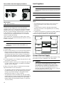
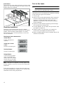
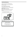
Side and Back View Gas Rangetop Installation
Gas Location
Connect the gas supply line to the unit pressure
regulator using a 1/2” flex gas line connector between
manual shut-off valve and pressure regulator. A metal
flex line or fixed metal pipe shall be used to connect gas
to the appliance. If a metal gas line cannot be used,
consult your local certified electrician or local electric
codes for proper grounding.
Check supply line connections for leaks using a soap
solution or non-corrosive leak detection fluid. Do not use
a flame of any sort.
9 WARNING
Install a gas shut off valve near the appliance. After
installation, it must be easily accessible in an
emergency.
1.
Turn on gas.
2.
Apply a soap solution or non-corrosive leak detection
fluid to all joints and fittings in the gas connection
between the shut-off valve and the cooktop. Include
gas fittings and joints in the cooktop if connections
may have been disturbed during installation. Bubbles
appearing around fittings and connections indicate a
leak.
3.
If a leak appears, turn off supply line gas shut-off valve
and tighten connections.
4.
Retest for leaks by turning on the supply line gas shut-
off valve. When leak check is complete (no bubbles
appear), test is complete.
5.
Wipe off all soap solution or detection fluid residue.
Important Notes for Gas Connection:
▯ The appliance and its individual gas shutoff valve must
be disconnected from the gas supply piping system
during any pressure testing of that system at test
pressures in excess of 1/2psi (3.5kPa).
▯ The appliance must be isolated from the gas supply
piping system by closing its individual manual shut-off
valve during any pressure testing of the gas supply
piping system at test pressures equal to or less than
1/2psi (3.5kPa).
Install Appliance
9 WARNING
Before you plug in an electrical cord or turn on
power supply, make sure all controls are in the OFF
position.
9 WARNING
Do not contact exposed regulator while placing
appliance in cabinetry.
Notes
▯ The appliance must sit securely in the cut-out and
must not be able to move around (e.g. during
cleaning).
▯ To help prevent cosmetic damage place plastic
shipping cover back over appliance prior to loading
into cabinetry.
▯ If additional construction is nearby the plastic shipping
cover can be used to preserve cosmetic finish.
Install the range top pushing it to the back wall.
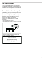
Connect Electrical Supply
The 120 V power cord is installed on gas rangetop. Plug
the power cord into a standard 120 V wall outlet.
9 WARNING
ELECTRICAL GROUNDING INSTRUCTIONS
This appliance is equipped with a three-prong
grounding plug to protect you against the risk of
shocks and it should be plugged directly into a
properly grounded receptacle. Do not cut or remove
the grounding prong from this plug.
A Gas connection
B Electrical connection
$
%

11
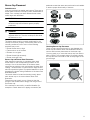
Burner Cap Placement
Sealed burners
Your new cooktop has sealed gas burners. There are no
burner parts under the cooktop to clean, disassemble or
adjust. Your cooktop has three different burner sizes:
small, large and dual-flame.
9 WARNING
To prevent flare-ups, do not use the cooktop without
all burner caps and all burner grates properly
positioned.
9 WARNING
To prevent burns, do not touch burner caps
orgrates while hot. Turn the cooktop off and allow
the burners to cool.
The burner parts must be correctly positioned for the
cooktop to function properly. If the burner parts are not
correctly positioned, one or more of the following
problems may occur:
▯ Burner flames are too high.
▯ Flames shoot out of burners.
▯ Burners do not ignite.
▯ Burner flames light unevenly.
▯ Burner emits gas odor.
Burner Cap and Burner Base Placement
After electrical connection is complete, place each
burner base on the corresponding location on the
cooktop. One of the three bars on the burner base
should line up with the notch and prevent the base from
rotating. The small hole or cutout near the edge should
also line up with the igniter. Pay special attention to avoid
damaging the igniter during installation of the base. See
Illustration below.
Once each base is located and resting evenly, place
each burner cap on its correct burner base. See
Illustration.
Place burner cap gently on top of base so that the
prongs of the burner base fit snugly into the groove of
the burner cap.
If the maintop is removed by a certified installer (for
example to check electrical or piping connection) the
panhead screws that were removed must be re-installed
to ensure proper functionality of burners.
Checking Burner Cap Placement
Check to make sure that there is no gap between the
burner cap and burner base. See illustration below for
correct and incorrect placements of the burner cap.
You may gently try to move the burner cap from side to
side to check if it is properly placed. If properly placed,
the cap will click from side to side as the prongs hit the
groove ridge.

12
Install Grates
First position the outer grates, followed by the the central
grate. If you only have two grates, the order in which you
position them is not relevant.
Check the Installation
Place each correct-sized burner cap in its seated,
notched position and check the operation of the electric
igniters. Check the flame characteristics. The flame
should be blue with a minimal yellow tip on the outer
cone of the flames.
Checking the flame characteristics
Note: If the flame is completely or mostly yellow, verify
that the regulator is set for the correct fuel. Retest after
adjustment.
Some yellow streaking is normal during the initial start-
up. Allow the appliance to operate for 4–5 minutes and
reevaluate before making adjustments.
Test for Gas Leaks
9 WARNING
RISK OF FIRE
Never check for gas leaks with a flame.
Leak testing is to be conducted by the installer according
to the instructions given in this section.
1.
Turn on gas.
2.
Apply a non-corrosive leak detection fluid. Include all
joints and fittings between the shutoff valve and the
appliance. Include gas fittings and joints in the
appliance if connections may have been disturbed
during installation.
3.
Inspect for leaks. Bubbles appearing around fittings
and connections indicate a leak.
4.
If a leak appears, turn off supply line gas shutoff valve
and tighten connections.
5.
Retest for leaks. Turn gas back on at supply line
shutoff valve and reapply leak detection fluid.
6.
When no bubbles appear, test is complete. Wipe off all
detection fluid residue.
Yellow flames:
Further adjustment is
required.
Yellow tips on outer
cones:
Normal for propane gas
Soft blue flames:
Normal for natural gas
Orange flames:
Can be normal if certain
types of humidifiers are
used in the home. Flames
should return to blue with-
out the humidifier running.

13
Conversion to Propane Gas (LPG)
Always provide adequate gas supply.
This appliance is shipped from the factory for use with
natural gas. Use this kit to convert the appliance for
propane gas use if necessary. Observe the following:
Ensure that the range is converted for use with the
appropriate gas before using it.
This appliance is designed to operate at a pressure of
10" of the water column when used with propane gas.
When checking for proper operation of the regulator, the
inlet pressure must be at least 1" greater than the
operating (manifold) pressure above. When converting
for propane gas use, the pressure supplied to the
regulator must be between 11" and 13" of the water
column.
The pressure regulator that is located in the inlet of the
range manifold must remain in the supply line.
Use a flexible metal appliance connector or rigid pipe to
connect the range to the gas supply. The connector
should have an inner diameter of 1/2” and be 5 ft
(1.5 m) or less in length. (Exception: Maximum connector
length in Massachusetts installations is 3 ft (0.9 m)). In
Canada, the connector must be single-wall metal and not
longer than 6 ft (1.8 m).
Save the orifices removed from the appliance for future
use.
9 CAUTION
The gas supply shall be shut off prior to
disconnecting the electrical power, before
proceeding with the conversion.
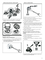
Parts included with propane gas nozzle set:
▯ 2x nozzle number 117
▯ 2x nozzle number 48
▯ 3x nozzle number 102
▯ 1x nozzle number 65
▯ 1x adhesive label
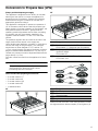
30”
36”
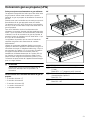
Make sure that the holes of the flame-spreader crowns
are aligned with the thermocouples (3) and igniters (4).
No. Designation
(
Dual-flame burner (18,000 BTU/ 5.3 kW)
LPG nozzles: 117 (external) and 48 (internal)
0
Small burner (5,000 BTU/ 1.5 kW)
OptiSim® feature
LPG nozzle: 65
8
Large burner (12,000 BTU/ 3.5 kW)
LPG nozzle: 102
No. Designation
(
Burner caps
0
Flame-spreader crowns
8
Thermocouples
@
Igniters

14
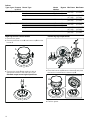
Orifices
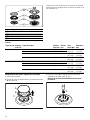
Replacing the main control nozzles
1.
Remove the grates.
2.
Remove the burner cover A and burner cup B from the
burner C.
3.
Remove the nozzle D and replace it with an
appropriate nozzle for the new type of gas.
Standard-output burner/high-output burner
Double-ring high-output burner
4.
Place the burner cup B onto the burner C and place
the burner cover A onto the burner cup B.
5.
Refit the grates.
Type of gas Pressure
in W.C.P.
Burner Type Nozzle
Number
Bypass Min Power Max Power
Natural gas 5” Dual-flame burner external 180(S4) Gap 1000 BTU
(0.3 kW)
18000 BTU
(5.3 kW)
Dual-flame burner internal 75 Gap
Large burner 152 Gap 2400 BTU
(0.7 kW)
12000 BTU
(3.5 kW)
Small burner 100 Gap 1000 BTU
(0.3 kW)
5000 BTU
(1.5 kW)
Liquid gas 10” Dual-flame burner external 117 55 1000 BTU
(0.3 kW)
18000 BTU
(5.3 kW)
Dual-flame burner internal 48 30
Large burner 102 45 2400 BTU
(0.7 kW)
12000 BTU
(3.5 kW)
Small burner 65 30 1000 BTU
(0.3 kW)
5000 BTU
(1.5 kW)
$
%
&
'
$
%
&

15
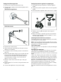
Setting the minimum gas flow
1.
Remove the control knob and knob ring.
2.
Turn the inner setting screw clockwise gently until it
bottoms out.
Small burner/large burner
Dual-flame burner:
3.
Replace the control knobs.
4.
Light each burner individually and check for flame
stability on low setting.
5.
If required, loosen the setting screw to increase the
gas flow.
6.
Ensure that the flame does not go out when the gas
flow is quickly changed between maximum and
minimum, and vice versa. The optimum setting is
achieved when the height of the small flame is
approx. 1/8" (3to 4 mm).
7.
Refit the control knob and knob ring for the gas
burner.
8.
Repeat steps 2to 8until all of the gas burners have
been set.
9.
Connect the appliance to the power supply.
Setting the pressure regulator for propane gas
1.
Use tongue and groove pliers to remove regulator
cap D.
2.
Unscrew the plastic regulator stem from the regulator
cap D.
3.
Invert the plastic regulator stem and screw it in tightly.
4.
Replace cover cap D and tighten with tongue &
groove pliers.
5.
When converting for propane gas use, the pressure
supplied to the regulator must be between 11" and
13" of the water column.
Checking functions after the conversion:
The flames must not go out when switching over swiftly
from the high to the low setting.
Note: Stick the adhesive label included with the nozzle
set over the rating plate of the appliance to document the
changeover to a different gas type.
Test for Gas Leaks
After the conversion it is important to verify the leakages.
~ Page 12
Conversion to natural gas
This appliance is shipped from the factory for use with
natural gas. If the appliance has been converted to
propane gas before, you have to convert it to natural gas
again.
Check the orifices for the right nozzles and, if required,
replace them. See "Replacing the main control nozzles".
Adjust the minimum gas flow. See "Setting the minimum
gas flow". The optimum setting is achieved when the
height of the small flame is approx. 1/8" (3to 4 mm).
Set the pressure regulator for natural gas. Turn the
spring plate the other way around as shown in "Setting
the pressure regulator for propane gas".
Save the orifices removed from the appliance for future
use.

16
Technical Service
Contact our Technical Service Department if your
appliance needs repair. Our Customer Service (see
below) will be happy to supply you with details how to
obtain a service repair.
How to Obtain Warranty Service
To obtain warranty service for your Product, you should
contact Bosch Customer Service at 1-800-944-2904to
schedule a repair.
Model (E) number and FD number
When you contact our service, please have the Model
(E) number and the FD number for your appliance
available.
You can find this information on the rating label
▯ on the back side of the appliance
▯ on the underside of the projecting control panel
Questions? Please contact us. We look forward to
hearing from you.
0DLQ6WUHHW6XLWH
,UYLQH&$
ZZZERVFKKRPHFRP

17
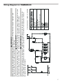
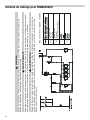
Wiring Diagram for RGM8658UC
.H\WRV\PEROVOHJHQGOH\HQGD
02
7HUPLQDOVWULS
%RUQLHU
%RUQHUD
$&
6SDUNLJQLWHU
$OOXPHXU
*HQHUDGRUGHFKLVSDV
/
1
:$51,1*
$9(57,66(0(17
$'9(57(1&,$
:KHQVHUYLFLQJWKHFRQWUROVODEHODOOZLUHVSULRUWRGLVFRQQHFWLRQ:LULQJHUURUVFDQFDXVHLPSURSHUDQG
GDQJHURXVRSHUDWLRQ9HULI\SURSHURSHUDWLRQDIWHUVHUYLFLQJ
(WLTXHWH]OHVILOVDYDQWGHGpFRQQHFWHUSRXUOHVFRQWUROHVGHVHUYLFH8QHHUUHXUGDQVOHILODJHSHXWSURYRTXHU
GHVRSpUDWLRQVGDQJHUHXVHVHWLQFRUUHFWHV9HULILH]ODFRQIRUPLWpGHO¶RSpUDWLRQDSUqVXQHQWUHWLHQ
0DUFDUWRGRVOHVFDEOHVDQWHVGHGHVFRQHFWDUDOUHDOL]DUHOPDQWHQLPLHQWRGHORVPDQGRV/RVHUURUHVGH
FRQH[LzQSXHGHQFDXVDUERSHUDFLRQHVLQDGHFXDGDV\SHOLJURVDV&RPSUREDUHOIXQFLRQDPLHQWRFRUUHFWR
GHVSXpVGHOPDQWHQLPLHQWR

18
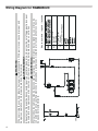
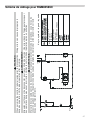
Wiring Diagram for RGM8058UC
:$51,1*
$9(57,66(0(17
$'9(57(1&,$
:KHQVHUYLFLQJWKHFRQWUROVODEHODOOZLUHVSULRUWRGLVFRQQHFWLRQ:LULQJHUURUVFDQFDXVHLPSURSHUDQG
GDQJHURXVRSHUDWLRQ9HULI\SURSHURSHUDWLRQDIWHUVHUYLFLQJ
(WLTXHWH]OHVILOVDYDQWGHGpFRQQHFWHUSRXUOHVFRQWUROHVGHVHUYLFH8QHHUUHXUGDQVOHILODJHSHXWSURYRTXHU
GHVRSpUDWLRQVGDQJHUHXVHVHWLQFRUUHFWHV9HULILH]ODFRQIRUPLWpGHO¶RSpUDWLRQDSUqVXQHQWUHWLHQ
0DUFDUWRGRVOHVFDEOHVDQWHVGHGHVFRQHFWDUDOUHDOL]DUHOPDQWHQLPLHQWRGHORVPDQGRV/RVHUURUHVGH
FRQH[LzQSXHGHQFDXVDUERSHUDFLRQHVLQDGHFXDGDV\SHOLJURVDV&RPSUREDUHOIXQFLRQDPLHQWRFRUUHFWR
GHVSXpVGHOPDQWHQLPLHQWR
.H\WRV\PEROVOHJHQGOH\HQGD
02
7HUPLQDOVWULS
%RUQLHU
%RUQHUD
$&
6SDUNLJQLWHU
$OOXPHXU
*HQHUDGRUGHFKLVSDV
/
1

19
Table des matières
Noti ce de montage
9 Définitions de sécurité ........................................... 19
CONSIGNES DE SÉCURITÉ IMPORTANTES ............. 20
Sécurité de manutention des appareils ........................ 21
Codes et normes de sécurité ......................................... 21
Sécurité électrique ............................................................ 21
Sécurité en matière de gaz ............................................. 21
Équipement de sécurité ................................................... 22
Conversion gaz au propane ............................................ 22
Installation à altitude élevée ............................................ 23
Avant de commencer .................................................. 24
Outils et pièces nécessaires ........................................... 24
Pièces comprises .............................................................. 24
Pour enlever l’emballage ................................................. 24
Informations générales ..................................................... 25
Exigences pour les placards ........................................... 25
Exigences pour le plan de travail ................................... 25
Caractéristiques techniques ........................................... 26
Liste de contrôle pour l'installation ................................ 26
Procédure d'installation ............................................. 26
Préparation des meubles ................................................ 26
Branchement du gaz ........................................................ 27
Pose de l'appareil ............................................................. 28
Brancher l'alimentation électrique .................................. 29
Montage des chapeaux de brûleur ............................... 29
Vérification de l'installation .............................................. 30
Test pour fuites de gaz .................................................... 30
Conversion gaz au propane (LPG) ............................ 31
Service technique ....................................................... 35
Comment bénéficier du service de garantie ............... 35
Schéma de câblage pour RGM8658UC ..................... 36
Schéma de câblage pour RGM8058UC ..................... 37
9 Définitions de sécurité
Défi nitions de sécurité
9 AVERTISSEMENT
Ceci indique que le non-respect de cet
avertissement peut entraîner des blessures graves,
voire la mort.
9 ATTENTION
Ceci indique que le non-respect de cet
avertissement peut entraîner des blessures légères
ou de gravité moyenne.
AVIS : Ceci indique que la non-conformité à cet avis de
sécurité peut entraîner des dégâts matériels ou
endommager l'appareil.
Remarque : Ceci vous signale des informations et/ou
indications importantes.

9 CONSIGNES DE SÉCURITÉ IMPORTANTES
LIRE ET CONSERVER CES INSTRUCTIONS
20
CONSI GNES DE SÉCURI TÉ IMPORTANTESLI RE ET CONS E RV E R CE S INSTRUCTIONS
Sécurité en mati ère de gaz
²
1HSDVFRQVHUYHURXXWLOLVHUGHOHVVHQFHRX
GDXWUHVOLTXLGHVRXYDSHXUVLQIODPPDEOHVj
SUR[LPLWpGHFHWDSSDUHLORXGHWRXWDXWUHDSSDUHLO
²
48()$,5(6,92863(5&(9(=81(2'(85'(*$=
1HSDVHVVD\HUGHPHWWUHXQDSSDUHLOVRXVWHQVLRQ
1HSDVWRXFKHUGLQWHUUXSWHXUGHFRXUDQWpOHFWULTXH
1HSDVXWLOLVHUGHWpOpSKRQHVGDQVOpGLILFH
&RPPXQLTXHULPPpGLDWHPHQWDYHFOHIRXUQLVVHXU
GHJD]GHSXLVODSSDUHLOWpOpSKRQLTXHGXQYRLVLQ
5HVSHFWHUOHVGLUHFWLYHVGXIRXUQLVVHXUGHJD]
6LOVDYqUHLPSRVVLEOHGHMRLQGUHOHIRXUQLVVHXUGH
JD]FRPPXQLTXHUDYHFOHVSRPSLHUV
²
8WLOLVHUOHVVHUYLFHVGXQLQVWDOODWHXURXGXQHDJHQFH
GHVHUYLFHVTXDOLILpVRXOHIRXUQLVVHXUGHJD]SRXU
SURFpGHUjOLQVWDOODWLRQHWDX[UpSDUDWLRQV
$9(57,66(0(176LOHVGLUHFWLYHVQHVRQWSDV
VXLYLHVjODOHWWUHLO\DXQULVTXHGLQFHQGLHRX
GH[SORVLRQSRXYDQWHQWUDvQHUGHVGRPPDJHV
PDWpULDX[GHVEOHVVXUHVRXXQGpFqV
La page charge ...
La page charge ...
La page charge ...
La page charge ...
La page charge ...
La page charge ...
La page charge ...
La page charge ...
La page charge ...
La page charge ...
La page charge ...
La page charge ...
La page charge ...
La page charge ...
La page charge ...
La page charge ...
La page charge ...
La page charge ...
La page charge ...
La page charge ...
-
 1
1
-
 2
2
-
 3
3
-
 4
4
-
 5
5
-
 6
6
-
 7
7
-
 8
8
-
 9
9
-
 10
10
-
 11
11
-
 12
12
-
 13
13
-
 14
14
-
 15
15
-
 16
16
-
 17
17
-
 18
18
-
 19
19
-
 20
20
-
 21
21
-
 22
22
-
 23
23
-
 24
24
-
 25
25
-
 26
26
-
 27
27
-
 28
28
-
 29
29
-
 30
30
-
 31
31
-
 32
32
-
 33
33
-
 34
34
-
 35
35
-
 36
36
-
 37
37
-
 38
38
-
 39
39
-
 40
40


Bosch RGM8058UC Guide d'installation
- Catégorie
- Cuisinières
- Taper
- Guide d'installation
- Ce manuel convient également à
dans d''autres langues
- italiano: Bosch RGM8058UC Guida d'installazione
- English: Bosch RGM8058UC Installation guide
Documents connexes
-
Bosch HGS8655UC Guide d'installation
-
Bosch HDS8645U Guide d'installation
-
Bosch NGM8057UC Manuel utilisateur
-
-
Bosch NGMP077UC Le manuel du propriétaire
-
Bosch Benchmark NGMP077UC Mode d'emploi
-
-
-
Bosch NGM8046UC LP Conversion Installation
-