Installation Manual
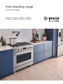
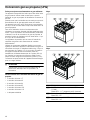
Free-standing range
HDS8055U, HDS8055C, HDS8045U, HDS8045C,
HDS8655U, HDS8655C, HDS8645U, HDS8645C


3
ö Installation Instructions
9 Safety Definitions ..................................................... 3
IMPORTANT SAFETY INSTRUCTIONS ........................ 4
Appliance Handling Safety ................................................. 5
Safety Codes and Standards ............................................. 5
Electric Safety ....................................................................... 5
Gas Safety ............................................................................. 6
Propane Gas Installation ..................................................... 6
Related Equipment Safety .................................................. 6
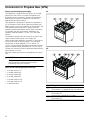
Conversion to Propane Gas ............................................... 7
High Altitude Installation ..................................................... 7
Before You Begin .......................................................... 8
Tools and Parts Needed ..................................................... 8
Parts Included ....................................................................... 8
Removing Packaging .......................................................... 8
General Information ............................................................. 9
Cabinet Requirements ......................................................... 9
Technical Data ................................................................... 10
Installation Checklist ......................................................... 11
Installation Procedure ................................................ 11
How to Remove the Oven Door ..................................... 11
Fitting the Rear Vent Trim ................................................ 12
Fitting the Adjustable Feet ............................................... 12
Connect Gas Supply ........................................................ 13
Install Appliance ................................................................ 14
Connect Electrical Supply ............................................... 16
Burner Cap Placement ..................................................... 20
Check the Installation ....................................................... 21
Test for Gas Leaks ............................................................ 21
Conversion to Propane Gas (LPG) ............................ 22
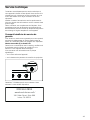
Technical Service ........................................................ 25
How to Obtain Warranty Service .................................... 25
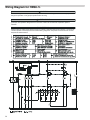
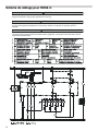
Wiring Diagram for HDS8..5. ...................................... 26
9 Safety Definitions
Safety Definitions
9 WARNING
This indicates that death or serious injuries may
occur as a result of non-observance of this warning.
9 CAUTION
This indicates that minor or moderate injuries may
occur as a result of non-observance of this warning.
NOTICE: This indicates that damage to the appliance or
property may occur as a result of non-compliance with
this advisory.
Note: This alerts you to important information and/or
tips.

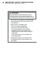
9 IMPORTANT SAFETY INSTRUCTIONS
READ AND SAVE THESE INSTRUCTIONS
4
IMPORTANT SAFET Y I NS T RUCT I ONSRE AD AND SAVE THESE INSTRUCTIONS
Gas Appli ance Safety
²
'RQRWVWRUHRUXVHJDVROLQHRURWKHUIODPPDEOH
YDSRUVDQGOLTXLGVLQWKHYLFLQLW\RIWKLVRUDQ\
RWKHUDSSOLDQFH
²
:+$772'2,)<2860(//*$6
'RQRWWU\WROLJKWDQ\DSSOLDQFH
'RQRWWRXFKDQ\HOHFWULFDOVZLWFK
'RQRWXVHDQ\SKRQHLQ\RXUEXLOGLQJ
,PPHGLDWHO\FDOO\RXUJDVVXSSOLHUIURPD
QHLJKERU·VSKRQH)ROORZWKHJDVVXSSOLHU·V
LQVWUXFWLRQV
,I\RXFDQQRWUHDFK\RXUJDVVXSSOLHUFDOO
WKHILUHGHSDUWPHQW
²
,QVWDOODWLRQDQGVHUYLFHPXVWEHSHUIRUPHG
E\DTXDOLILHGLQVWDOOHUVHUYLFHDJHQF\RUWKH
JDVVXSSOLHU
,IWKHLQIRUPDWLRQLQWKHVHLQVWUXFWLRQVLVQRW
IROORZHGH[DFWO\DILUHRUH[SORVLRQPD\UHVXOW
FDXVLQJSURSHUW\GDPDJHSHUVRQDOLQMXU\RUGHDWK
:$51,1*

5
9 IMPORTANT SAFETY INSTRUCTIONS
READ AND SAVE THESE INSTRUCTIONS
IMPORTANT: THE APPLIANCE MUST BE INSTALLED BY
A QUALIFIED INSTALLER.
INSTALLER: LEAVE THESE INSTRUCTIONS WITH THE
APPLIANCE AFTER INSTALLATION IS COMPLETE.
IMPORTANT: SAVE FOR THE LOCAL INSPECTOR’S
USE.
WARNING
If the information in this manual is not followed exactly,
fire or shock may result causing property damage or
personal injury.
WARNING
Do not repair, replace or remove any part of the
appliance unless specifically recommended in the
manuals. Improper installation, service or maintenance
can cause injury or property damage. Refer to this
manual for guidance. All other servicing should be done
by an authorized service provider.
Improper installation is not covered by the warranty.
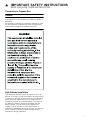
WARNING
TIP OVER HAZARD
Appliance Handling Safety
Wear gloves to avoid cutting fingers on sharp edges
during Installation.
Unit is heavy and requires at least two persons or proper
equipment to move.
Do not lift appliance by the oven door handle. Remove
the oven door for easier handling and installation See the
section "Removing/Replacing the Oven Door".
Do not use the oven for storage.
Safety Codes and Standards
This appliance complies with one or more of the
following standards:
▯ UL 858, The Standard for the Safety of Household
Electric Ranges
▯ ANSI Z21.1/CSA 1.1Household Cooking Gas
Appliances
▯ CAN/CSA-C22.2No. 61Household Cooking Ranges
It is the responsibility of the owner and the installer to
determine whether additional requirements and/or
standards apply to specific installations.
Installation must conform with local codes or, in the
absence of local codes, with the National Fuel Gas
Code, ANSI Z223.1/NFPA 54or, in Canada, the Natural
Gas and Propane Installation Code, CSA B149.1.
The appliance must be electrically grounded in
accordance with local codes or, in the absence of local
codes, with the National Electrical Code, NFPA 70latest
edition or, in Canada, the Canadian Electric Code, CSA
C22.1-02.
Electric Safety
WARNING
Before you plug in an electrical cord or turn on power
supply, make sure all controls are in the OFF position.
Be sure your appliance is properly installed and
grounded by a qualified technician. Installation, electrical
connections and grounding must comply with all
applicable codes.
Before installing, turn power OFF at the service panel.
Lock service panel to prevent power from being turned
ON accidentally.
For appliances equipped with a cord and plug, do not
cut or remove the ground prong. It must be plugged into
a matching grounding type receptacle to avoid electrical
shock. If there is any doubt as to whether the wall
receptacle is properly grounded, the customer should
have it checked by a qualified electrician.
Do not use an extension cord.
A child or adult can tip the
range over and be killed.
Install the anti-tip device
to the structure and/or the
range. Verify the anti-tip
device has been properly
installed and engaged.
Engage the range to the
anti-tip device. Ensure the
anti-tip device is re-
engaged when the range
is moved.
Re-engage the anti-tip device if the range is moved.
Do not operate the range without the anti-tip device
in place and engaged.
See installation instructions for details.
Failure to follow the instructions in this manual can
result in death or serious burns to children and
adults.
Check for proper installation and use of the anti-tip
bracket. Carefully tip the range forward pulling from
the back to ensure that the anti-tip bracket engages
the range leg and prevents tip-over. The range
should not move more than 1” (2.5cm).
Hidden surfaces may have sharp edges.
Use caution when reaching behind or
under appliance.

9 IMPORTANT SAFETY INSTRUCTIONS
READ AND SAVE THESE INSTRUCTIONS
6
Do not use an adapter.
If required by the National Electrical Code (or Canadian
Electrical Code), this appliance must be installed on a
separate branch circuit.
The circuit breaker should have a contact separation of
at least 3mm on all poles.
Installer – show the owner the location of the circuit
breaker or fuse. Mark it for easy reference.
Refer to rating label for more information. See "How to
Obtain Warranty Service" under "Technical Service" for
rating label location.
Gas Safety
Install a gas shutoff valve near the appliance. It must be
easily accessible in an emergency.
Leak testing must be conducted by the installer
according to the instructions in this manual.
The appliance and its individual shutoff valve must be
disconnected from the gas supply piping system during
any pressure testing at pressures in excess of ½ psi
(3.5kPa).
The appliance must be isolated from the gas supply
piping system by closing its individual manual shutoff
valve during any pressure testing of the gas supply
piping system at test pressures equal to or less than
½ psi (3.5 kPa).
The minimum supply pressure must be 1" water column
above the manifold pressure printed on the rating label.
The maximum supply pressure must not exceed
14.0inches water column (34.9 Millibars).
IMPORTANT SAFETY NOTICE: Burning gas cooking fuel
generates some by-products which are on the list of
substances which are known by the State of California to
cause cancer or reproductive harm. To minimize
exposure to these substances, always operate this unit
according to the instructions contained in this booklet
and provide good ventilation.
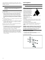
Proposition 65Warning:
This product may contain a chemical known to the State
of California, which can cause cancer or reproductive
harm. Therefore, the packaging of your product may
bear the following label as required by California:
Propane Gas Installation
The propane gas tank must be equipped with its own
high pressure regulator. In addition, the regulator
supplied with this unit must also be used.
The appliance is shipped from the factory for use with
natural gas. It must be converted for use with propane. A
qualified technician or installer must do the conversion.
This appliance has been certified for safe operation up to
a height of 10,000 ft. Exception: To use it with propane
gas, the appliance must be converted in accordance with
the propane conversion instructions.
For Massachusetts installations:
▯ Installation must be performed by a qualified or
licensed contractor, plumber or gas fitter qualified or
licensed by the state, province or region where this
appliance is being installed.
▯ Shut-off valve must be a “T” handle gas cock.
▯ Flexible gas connector must not be longer than
36 inches.
Installer - show the owner where the gas shut-off valve is
located.
Related Equipment Safety
The appliance should only be used if installed by a
qualified technician in accordance with these installation
instructions and all applicable regulations and codes.
The manufacturer is not responsible for damages
resulting from incorrect installation.
Remove all tape and packaging before using the
appliance. Destroy the packaging after unpacking the
appliance. Never allow children to play with packaging
material.
Never modify or alter the construction of the appliance.
For example, do not remove leveling legs, panels, wire
covers or anti-tip brackets/screws.
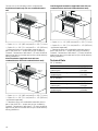
To eliminate the risk of burns or fire by reaching over
heated surface units, cabinet storage space located
above the surface units should be avoided. If cabinet
storage is to be provided, the risk can be reduced by
installing a hood that projects horizontally a minimum of
5inches (127 mm) beyond the bottom of the cabinet.
Verify that cabinets above the cooktop are a maximum of
13" (330 mm) deep.
When installing a cooktop over a single oven, be sure to
follow both the oven’s and cooktop’s installation
manuals.
Ventilation Recommendations
We strongly recommend the installation of a ventilation
hood above this appliance. The hood must be installed
according to instructions furnished with the hood.
CAUTION
The appliance should not be installed with a ventilation
system that blows air downward toward the burners. This
type of ventilation system may cause ignition and
combustion problems with the gas cooking appliance
resulting in personal injury or unintended operation.
&DQFHUDQG5HSURGXFWLYH+DUPZZZ3:DUQLQJVFDJRY
67$7(2)&$/,)251,$352326,7,21:$51,1*
:$51,1*

7
9 IMPORTANT SAFETY INSTRUCTIONS
READ AND SAVE THESE INSTRUCTIONS
Conversion to Propane Gas
WARNING
Personal injury or death from electrical shock may occur
if the appliance is not installed by a qualified installer or
electrician.
Any additions, changes or conversions required in order
for this appliance to satisfactorily meet the application
needs must be made by a qualified technician.
High Altitude Installation
This appliance has been tested for operation up to an
altitude of 10,000ft (3,048m) elevation above sea level.
If desired, for altitudes above 2,000 ft (610 m) elevation
above sea level, adjustments may be made. Burners
should be checked at the lowest setting, if the flame is
not stable the simmer should be increased until the
flame is stable. This can be done by adjusting the
bypass screw in the valve. If flame performance is
satisfactory, adjustment will not be required. It is required
that a Certified Professional make the high altitude
adjustments during installation.

8
Before You Begin
Before You Begin
Tools and Parts Needed
▯ Phillips head screwdriver
▯ Slotted screwdriver 1/8" (3,5 mm)
▯ Adjustable wrench
▯ Tongue and groove pliers
▯ Socket or flat wrench 3/8” (10mm) or tongs
▯ Socket or flat wrench 7/8” (22mm) or tongs
▯ Drill with 5/16" (8mm) bit
▯ Pencil
▯ Tape measure
Only needed for appliances without power cord:
▯ Tube hexagonal wrench with nut head 3/8” (10mm)
▯ Tube hexagonal wrench with nut head 5/16” (8mm)
▯ Power Supply Cord (only for USA)
Note: Additional materials may be necessary for
installation in solid surface countertops. Contact the
countertop manufacturer.
Parts Included
30”:
36”:
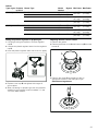
Removing Packaging
See the diagram on the packaging.
▯ If straps are present, cut the straps.
▯ Cut plastic down back of unit making sure not to cut
the unit.
▯ Remove plastic film.
▯ Lift the cardboard carton from the top of the range and
dispose of.
▯ Remove the corner posts, making sure that any other
packing materials running between the corner posts
are also removed.
▯ Remove all internal packaging and tape.
▯ The rear vent trim is nested in the styrofoam
packaging for shipping purposes. Do not throw away.
[[ [
[[ [

9
General Information
30”:
36”:
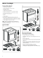
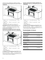
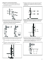
Cabinet Requirements
X = Grounded Outlet
Y = Gas Supply Line
The minimum spaces that must be maintained when
installing the gas cooktop shall be:
èʌʓʘ
èʌʓʘ
ʎʓʘ
ʐʓʘ
èʔ
ʌʚ
èʌʓʘ
ʐʓʘ
²ʐʓʘ
²
èʋʓʘ
²æʓʘ
²
èʌʓʘ
ʌʓʘ
ʎʓʘ
ʐʓʘ
èʔ
èʋʓʘ
èèʓʘ
²èæʓʘ
²
ʐʓʘ
²ʐʓʘ
²
ʎʚ
B minimum 18" (457 mm)
C minimum 30" (762 mm) clearance between
the top of the cooking surface and the
bottom of the unprotected wood or metal
cabinet
D 30": minimum 30" (762 mm)
36": minimum 36" (914 mm)
E minimum 25" (635 mm)
F maximum 13" (330 mm)
G 30": minimum 30" (762 mm)
36": minimum 36" (914 mm)
Zero clearance between adjacent
combustible construction below the
countertop surface and sides of the
appliance.
H 35"6/16- 36"10/16(898- 930 mm)
I 11" (279 mm)
J 7" (178 mm)
K 6" (150 mm)
L 11" (279 mm)
'
&
%
+
-
,
.
*
(
)
/
/
/
[
\

10
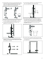
Choose one of the following built-in configurations.
Installation allowed only with non combustible back
wall
▯ Option 1: A >= 12'' (305 mm) and B >= 28'' (711 mm)
▯ Option 2: A >= 28'' (711 mm) and B >= 12'' (305 mm)
* Clearances from non-combustible materials are not
part of the ANSI Z21.1scope and are not certified by
“Intertek”. Clearances of less than 3'' (76 mm) should be
approved by the local codes and/or by the local authority
having jurisdiction.
Island Installation (applicable both with non
combustible back wall and combustible back wall)
▯ Option 1: A >= 12'' (305 mm) and B >= 28'' (711 mm)
▯ Option 2: A >= 28'' (711 mm) and B >= 12'' (305 mm)
* purchased separately
** Clearances from non-combustible materials are not
part of the ANSI Z21.1scope and are not certified by
“Intertek”. Clearances of less than 3'' (76 mm) should be
approved by the local codes and/or by the local authority
having jurisdiction.
Low Backguard Installation (applicable both with non
combustible back wall and combustible back wall)
▯ Option 1: A >= 12'' (305 mm) and B >= 28'' (711 mm)
▯ Option 2: A >= 28'' (711 mm) and B >= 12'' (305 mm)
* purchased separately
** Clearances from non-combustible materials are not
part of the ANSI Z21.1scope and are not certified by
“Intertek”. Clearances of less than 3'' (76 mm) should be
approved by the local codes and/or by the local authority
having jurisdiction.
Technical Data
30” (5burners):
36” (6burners):
%
$
PLQ
%
$
Total connected load electric 1 A (120 W)
Total connected load gas
(natural gas)
48,000BTU/h
(14.1 kW)
Total connected load gas
(propane gas)
48,000BTU/h
(14.1 kW)
Total connected load electric 1 A (120 W)
Total connected load gas
(natural gas)
63,000BTU/h
(18.4 kW)
Total connected load gas
(propane gas)
63,000BTU/h
(18.4 kW)
%
$

11
Installation Checklist
Please refer to the pages following for complete
installation instructions. Use this checklist to verify that
you have completed each step of the installation
process. This can help you avoid mistakes.
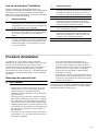
Installation Procedure
Installati on Procedure
An air curtain or other overhead range hood, which
operates by blowing a downward airflow onto a range,
shall not be used in conjunction with the gas range
unless the hood and range have been designed and
tested in accordance with ANSI Z21.1and listed by an
independent testing laboratory for combination use.
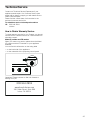
How to Remove the Oven Door
9 WARNING
▯ Make sure the oven is cool and the power to the
oven has been turned off before removing the
door. Failure to do so could result in electrical
shock or burns.
▯ The oven door is heavy and parts of it are fragile.
Use both hands to remove the oven door. The
door front is glass. Handle carefully to avoid
breaking.
▯ Grasp only the side of the oven door. Do not
grasp the handle as it may swing in your hand
and cause damage or injury.
▯ Failure to grasp the oven door firmly and properly
could result in personal injury or product damage.
▯ To avoid injury from the hinge bracket snapping
closed, make sure that both levers are securely in
place before removing the door. Also, do not
force the door open or closed – this could
damage the hinge or result in injury.
▯ Do not place the removed door down on sharp or
pointed objects as this could break the glass. Lay
on a flat, smooth surface, positioned so that the
door cannot fall over.
To avoid injury or damage, make sure that you read the
above WARNING before attempting to remove the oven
door.
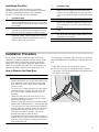
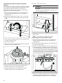
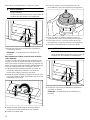
1.
Open the oven door to its fully open position.
2.
Lock the two hinges on the left and right using the
locking pin. The locking pins must be fully inserted into
the holes in the hinges.
è
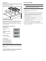
Installation step
Before installing the range, be sure to verify the
cabinet dimensions are correct for your unit and
that the required electrical and gas connections
are present.
Before installing the range, make sure that any
opening in the wall behind the appliance and in
the floor under the appliance shall be sealed.
Refer to the installation manual for content
regarding Safety, Cabinet Dimensions, Remov-
ing Packaging, Electrical Installation, Gas Con-
nection, and Customer Service.
Removing the oven door prior to installation
reduces the unit weight and makes the range
easier to move. Additionally, the removal of the
oven door provides access to handholds for lift-
ing.
Fitting the adjustable feet.
Move the range (2people needed) into place in
front of the installation opening, leaving the bot-
tom packaging on the unit to avoid damaging
flooring.
Plug the range into a properly configured recep-
tacle.
Protect the flooring from damage, then slide the
unit all the way into place, making sure to route
the power cord correctly.
Reinstall the oven door.
è
Installation step

12
3.
Close the oven door until it catches on the hinge stop
levers, locking the hinges at the correct angle for door
removal. The door can be removed when it is pulled
up from the open position by about 8 inches
(203 mm). This takes the tension off the spring-loaded
hinges so that the door can be easily lifted out.
9 CAUTION
RISK OF PINCHING
Closing the door by 8" (203 mm) takes the
pressure off the spring. If this is not done, the
door can still be removed but the latch will now
slam shut and will pinch or cut your hand.
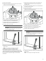
4.
The door is heavy. Use both hands to firmly grip it by
the sides. Do not grip the door by the handle. Keeping
the angle of the door the same, lift the door straight up
approximately 3/4" (19 mm) to unhook the hinges
from the slots, and then pull it out towards you until the
hinges are clear of the oven housing.
5.
Place the door in a convenient and stable location for
cleaning.
6.
Refit the door in the reverse order in which it was
removed.
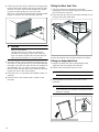
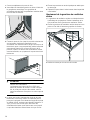
Fitting the Rear Vent Trim
1.
The rear vent trim is nested in the styrofoam
packaging. Remove the packaging and the protective
film from the rear vent trim.
2.
Place the rear vent trim into the holes intended for this
purpose using the dowel pins.
3.
Insert and tighten the enclosed screws from below.
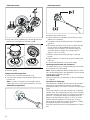
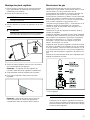
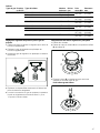
Fitting the Adjustable Feet
1.
Remove all parts that are not permanently fixed,
especially the pan supports and burners.
2.
Remove the accessories from the oven.
9 CAUTION
Protect the floor.
3.
Tilt the appliance and put it to the floor on the
backside.
9 CAUTION
Do not use the door handle or projecting control
panel for carrying.
´

13
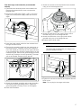
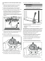
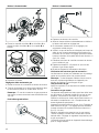
4.
Screw the adjustable feet into the mounting holes on
the underside of the appliance.
Note: If the appliance needs to be moved again,
screw the adjustable feet in fully.
5.
Carefully move the appliance back on the feets.
6.
Turn the adjustable feet to align the appliance.
Note: Measure the installation height of the cabinetry
and adjust appliance height accordingly prior to
placing appliance in cabinetry.
Connect Gas Supply
The appliance is shipped from the factory for use with
natural gas at a pressure of 5" of the water column.
When checking for proper operation of the regulator, the
inlet pressure must be at least 1" greater than the
operating (manifold) pressure above. When used with
natural gas, the pressure supplied to the regulator must
be between 6" and 10,5" of the water column.
To convert the appliance to propane gas see
“Conversion to propane gas (LPG)”. A qualified
technician or installer must do the conversion.
Use a flexible gas pipe with a length of at least 5 ft
(1.5 m).
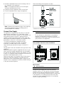
The gas inlet to the unit is located at the right rear of the
appliance.
Install the pressure regulator (supplied with unit) to gas
inlet. Postion the gasket (supplied with unit) in between
the inlet and the regulator. Position the regulator to have
it cap D (~ Page 23) easily accessible. Turn the nut on
gas inlet to hand tighten plus 1/3 turn.
Install the gas pipe to the regulator using Teflon tape or
pipe-joint compound (resistant to propane gas and
natural gas). Turn to hand tighten plus 1/3turn. Do not
exceed 1 turn for alignment, to prevent possible damage
to the gas pressure regulator.
Check inlet fittings and regulator for leaks.
* Attached to the appliance.
9 WARNING
Do not attempt any adjustment of the pressure
regulator, except when converting to propane.
Adjustments could lead to leaks or cause incorrect
gas pressure to the appliance.
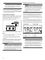
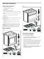
Side and Back View Gas Cooker Installation
Gas Location
Connect the gas supply line to the unit pressure
regulator using a 1/2” flex gas line connector between
manual shut-off valve and pressure regulator. A metal
flex line or fixed metal pipe shall be used to connect gas
to the appliance. If a metal gas line cannot be used,
consult your local certified electrician or local electric
codes for proper grounding.
A Gas connection
B Electrical connection
%
$

14
Check supply line connections for leaks using a soap
solution or non-corrosive leak detection fluid. Do not use
a flame of any sort.
9 WARNING
Install a gas shut off valve near the appliance. After
installation, it must be easily accessible in an
emergency.
1.
Turn on gas.
2.
Apply a soap solution or non-corrosive leak detection
fluid to all joints and fittings in the gas connection
between the shut-off valve and the cooktop. Include
gas fittings and joints in the cooktop if connections
may have been disturbed during installation. Bubbles
appearing around fittings and connections indicate a
leak.
3.
If a leak appears, turn off supply line gas shut-off valve
and tighten connections.
4.
Retest for leaks by turning on the supply line gas shut-
off valve. When leak check is complete (no bubbles
appear), test is complete.
5.
Wipe off all soap solution or detection fluid residue.
Important Notes for Gas Connection:
▯ The appliance and its individual gas shutoff valve must
be disconnected from the gas supply piping system
during any pressure testing of that system at test
pressures in excess of 1/2psi (3.5kPa).
▯ The appliance must be isolated from the gas supply
piping system by closing its individual manual shut-off
valve during any pressure testing of the gas supply
piping system at test pressures equal to or less than
1/2psi (3.5kPa).
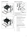
Install Appliance
9 WARNING
TIP OVER HAZARD
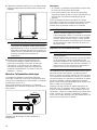
Installing the anti-tip bracket
1.
Ensure that the electrical connection and the gas
connection are in the correct position.
2.
Assemble the bracket.
A child or adult can tip the
range over and be killed.
Install the anti-tip device
to the structure and/or the
range. Verify the anti-tip
device has been properly
installed and engaged.
Engage the range to the
anti-tip device. Ensure the
anti-tip device is re-
engaged when the range
is moved.
Re-engage the anti-tip device if the range is moved.
Do not operate the range without the anti-tip device
in place and engaged.
See installation instructions for details.
Failure to follow the instructions in this manual can
result in death or serious burns to children and
adults.
Check for proper installation and use of the anti-tip
bracket. Carefully tip the range forward pulling from
the back to ensure that the anti-tip bracket engages
the range leg and prevents tip-over. The range
should not move more than 1” (2.5cm).

15
3.
Align the base of the hook of the bracket with the base
on the slot of the rear wall fastening bracket. Align the
base of the fastening bracket with the ground and
tighten the screws to fix the measurements.
4.
For wall mounting, proceed with steps 5–7and 10.
For floor mounting, proceed with steps 8–9and 10.
5.
Use the specified distance from the side of the
appliance to the bracket holes.
6.
Move the bracket onto the wall and fix with the two
washers and screws. A qualified technician must verify
suitability of the materials in accordance with the type
and condition of the wall.
7.
Use the following distances for the distance from the
side of the appliance to the bracket holes.
8.
After having positioned and leveled the appliance,
move the bracket close to the rear of the appliance
and anchor it to the floor with the two washers and
screws. A qualified technician must verify suitability of
the materials in accordance with the type and
condition of the floor.
9.
Push the cooker towards the wall, and at the same
time, insert the bracket in the plate fastened to the rear
of the appliance.
çʓʘ
èʚ
ʎʓʘ
ʌʚ

16
9 WARNING
The rear vent trim has 3/16” (5 mm) standoffs to
keep the appliance slightly off of the back wall.
Do not remove or tamper with standoffs due to
potential temperature issues.
10.
Check for proper installation and use of the anti-tip
bracket. Carefully tip the range forward pulling from
the back to ensure that the anti-tip bracket engages
the range leg and prevents tip-over. The range should
not move more than 1” (2.5cm).
Connect Electrical Supply
The Dual Fuel slide in range may be connected using an
electric range cord or using a flexible conduit electrical
connection. The length must be at least 1,5 m.
For technical specifications see the rating label on the
underside of the projecting control panel.
Do not use multiple outlets, extension leads or adapters.
Notes
▯ In Canada, the range is shipped from the factory with
the range cord already installed.
▯ We recommend that only qualified persons add a
power cord or make electrical connections to this
appliance.
For installations other than those in Canada, connect the
range cord at the terminal block. Access the terminal
block by removing the cover in the lower right-hand
corner of the range back panel.
9 WARNING
ELECTRICAL GROUNDING INSTRUCTIONS
This appliance (HDS8..5C) is equipped with a four-
prong grounding plug for your protection against
shock hazard and should be plugged directly into a
properly grounded receptacle. Do not cut or remove
the grounding prong from this plug.
Preparation for Power Connection
9 WARNING
WARNING
Risk of Electric Shock or Fire. Grounding through
the neutral conductor is prohibited for new branch-
circuit installations (1996NEC), mobile homes, and
recreational vehicles, or in an area where local
codes prohibit grounding through the neutral
conductor.
For installations where grounding through the neutral
conductor is prohibited: (a) disconnect the link from the
neutral, (b) use grounding terminal or lead to ground
unit, (c) connect neutral terminal to lead branch circuit
neutral in the usual manner. When the appliance is to be
connected by means of a cord kit, use 4-conductor cord
for this purpose.
Use only cord kits rated 208/240 volts, 50 amperes, with
ring or fork type connector and labelled "For use with
ranges”. Use only flexible conduit with wires with ring or
fork type connectors. Strain relief provided with the cord
must be installed per instructions included with the cord.
9 WARNING
WARNING
To prevent electrical shock, the grounding prong on
the range cord should not be cut or removed under
any circumstances. It must be plugged into a
matching grounding type receptacle and connected
to a correctly polarized 240-Volt circuit. If there is
any doubt as to whether the wall receptacle is
properly grounded, have it checked by a qualified
electrician.
3-Wire Hookup 4-Wire Hookup
R= Red
W = White
GS = Grounding Strip
B = Black
R= Red
W = White
G = Green
B = Black
*6
:
%
5
*
%
:
5

17
Four-wire range cord connection (recommended
method)
1.
Disconnect the electrical power at the breaker box.
Remove the terminal block cover to expose the
terminal block.
2.
Remove the metal plate. Rotate it 180° to have the
lager hole for the power supply cable and mount it
again.
3.
Insert the power supply cable into the terminal block
through the bottom hole.
4.
Remove the grounding strap from the center post on
the terminal block. Therefore remove the hexagonal
nut of the neutral pin. Remove the fork type connector
of the groundling link. Mount the hexagonal nut on the
neutral pin again. Remove the green hexagonal screw
and the ring connector from the grounding. The strap
will not be needed. Remove it from the unit.
5.
Attach the insulated grounding wire to the grounding
hole with the green grounding screw. Tighten the
green hexagonal nut firmly, but do not overtighten.
6.
Insert the flat washer.
7.
Attach the red wire to the left junction block terminal
using one of the hexagonal nuts.
8.
Attach the white wire to the center junction block
terminal using one of the hexagonal nuts.
9.
Attach the black wire to the right junction block
terminal using one of the hexagonal nuts.
10.
Properly secure strain relief.
9 WARNING
WARNING
The strain relief provided with your range cord
must be installed correctly.
11.
Tighten all connections securely and replace terminal
block cover.
Note: Do not plug in the range at this time.

18
Connecting the three-wire range cord (alternate
method)
The four-wire connection (above) is preferred, but where
local codes and ordinances permit grounding through
the neutral and where conversion to four-wire is
impractical, the unit can be connected to the power
supply via a three-wire connection.
1.
Disconnect the electrical power at the breaker box.
Remove the terminal block cover to expose the
terminal block.
2.
Remove the metal plate. Rotate it 180° to have the
lager hole for the power supply cable and mount it
again.
3.
Insert the power supply cable into the terminal block
through the bottom hole.
4.
Insert the flat washer.
5.
Attach the red wire to the left junction block terminal
using one of the hexagonal nuts.
6.
Attach the white wire to the center junction block
terminal using one of the hexagonal nuts.
7.
Attach the black wire to the right junction block
terminal using one of the hexagonal nuts.
8.
Properly secure strain relief.
9 WARNING
WARNING
The strain relief provided with your range cord
must be installed correctly.
9.
Tighten all connections securely and replace terminal
block cover.
Note: Do not plug in the range at this time.
Connecting the four-wire flexible conduit
1.
Disconnect the electrical power at the breaker box.
Remove the terminal block cover to expose the
terminal block.
2.
Insert the power supply cable into the terminal block
through the bottom hole.
3.
Remove the grounding strap from the center post on
the terminal block. Therefore remove the hexagonal
nut of the neutral pin. Remove the fork type connector
of the groundling link. Mount the hexagonal nut on the
neutral pin again. Remove the green hexagonal screw
and the ring connector from the grounding. The strap
will not be needed. Remove it from the unit.
4.
Attach the insulated grounding wire to the grounding
hole with the green grounding screw. Tighten the
green hexagonal nut firmly, but do not overtighten.

19
5.
Insert the flat washer.
6.
Attach the red wire to the left junction block terminal
using one of the hexagonal nuts.
7.
Attach the white wire to the center junction block
terminal using one of the hexagonal nuts.
8.
Attach the black wire to the right junction block
terminal using one of the hexagonal nuts.
9.
Properly secure strain relief.
9 WARNING
WARNING
The strain relief provided with your range cord
must be installed correctly.
10.
Tighten all connections securely and replace terminal
block cover.
Note: Do not plug in the range at this time.
Connecting the three-wire flexible conduit
The four-wire connection is preferred, but where local
codes and ordinances permit grounding through neutral
and/or conversion to four-wire is impractical, the unit can
be connected to the power supply via a three-wire
connection.
1.
Disconnect the electrical power at the breaker box.
Remove the terminal block cover to expose the
terminal block.
2.
Insert the power supply cable into the terminal block
through the bottom hole.
3.
Insert the flat washer.
4.
Attach the red wire to the left junction block terminal
using one of the hexagonal nuts.
5.
Attach the white wire to the center junction block
terminal using one of the hexagonal nuts.
6.
Attach the black wire to the right junction block
terminal using one of the hexagonal nuts.
7.
Properly secure strain relief.
9 WARNING
WARNING
The strain relief provided with your range cord
must be installed correctly.
8.
Tighten all connections securely and replace terminal
block cover.
Note: Do not plug in the range at this time.

20
Burner Cap Placement
Sealed burners
Your new cooktop has sealed gas burners. There are no
burner parts under the cooktop to clean, disassemble or
adjust. Your cooktop has three different burner sizes:
small, large and dual-flame.
9 WARNING
To prevent flare-ups, do not use the cooktop without
all burner caps and all burner grates properly
positioned.
9 WARNING
To prevent burns, do not touch burner caps
orgrates while hot. Turn the cooktop off and allow
the burners to cool.
The burner parts must be correctly positioned for the
cooktop to function properly. If the burner parts are not
correctly positioned, one or more of the following
problems may occur:
▯ Burner flames are too high.
▯ Flames shoot out of burners.
▯ Burners do not ignite.
▯ Burner flames light unevenly.
▯ Burner emits gas odor.
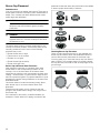
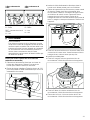
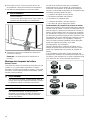
Burner Cap and Burner Base Placement
After electrical connection is complete, place each
burner base on the corresponding location on the
cooktop. One of the three bars on the burner base
should line up with the notch and prevent the base from
rotating. The small hole or cutout near the edge should
also line up with the igniter. Pay special attention to avoid
damaging the igniter during installation of the base. See
Illustration below.
Once each base is located and resting evenly, place
each burner cap on its correct burner base. See
Illustration.
Place burner cap gently on top of base so that the
prongs of the burner base fit snugly into the groove of
the burner cap.
If the maintop is removed by a certified installer (for
example to check electrical or piping connection) the
panhead screws that were removed must be re-installed
to ensure proper functionality of burners.
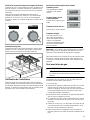
Checking Burner Cap Placement
Check to make sure that there is no gap between the
burner cap and burner base. See illustration below for
correct and incorrect placements of the burner cap.
You may gently try to move the burner cap from side to
side to check if it is properly placed. If properly placed,
the cap will click from side to side as the prongs hit the
groove ridge.
La page charge ...
La page charge ...
La page charge ...
La page charge ...
La page charge ...
La page charge ...
La page charge ...
La page charge ...
La page charge ...
La page charge ...
La page charge ...
La page charge ...
La page charge ...
La page charge ...
La page charge ...
La page charge ...
La page charge ...
La page charge ...
La page charge ...
La page charge ...
La page charge ...
La page charge ...
La page charge ...
La page charge ...
La page charge ...
La page charge ...
La page charge ...
La page charge ...
La page charge ...
La page charge ...
La page charge ...
La page charge ...
-
 1
1
-
 2
2
-
 3
3
-
 4
4
-
 5
5
-
 6
6
-
 7
7
-
 8
8
-
 9
9
-
 10
10
-
 11
11
-
 12
12
-
 13
13
-
 14
14
-
 15
15
-
 16
16
-
 17
17
-
 18
18
-
 19
19
-
 20
20
-
 21
21
-
 22
22
-
 23
23
-
 24
24
-
 25
25
-
 26
26
-
 27
27
-
 28
28
-
 29
29
-
 30
30
-
 31
31
-
 32
32
-
 33
33
-
 34
34
-
 35
35
-
 36
36
-
 37
37
-
 38
38
-
 39
39
-
 40
40
-
 41
41
-
 42
42
-
 43
43
-
 44
44
-
 45
45
-
 46
46
-
 47
47
-
 48
48
-
 49
49
-
 50
50
-
 51
51
-
 52
52


Bosch HDS8045U Guide d'installation
- Catégorie
- Cuisinières
- Taper
- Guide d'installation
dans d''autres langues
- italiano: Bosch HDS8045U Guida d'installazione
- English: Bosch HDS8045U Installation guide