
Installation Instructions
Instructions de montage
Instrucciones de montaje
Document No. 129-307
January 21, 2013
OpenAir™ GMA Series
Rotary spring return actuator
Servomoteur à action angulaire avec ressort de rappel
Accionador giratorio de retorno por muelle
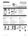
Contents Contenu Contenido
a
b
i
e
g
h
d
c
4.8 x 13
DIN 7981
f
EA0879R3
MANUAL
OVERRIDE
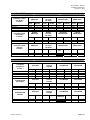
a. Actuator
b. Self-centering shaft adapter
c. Position indicator
d. Shaft adapter locking clip
e. Position indicator adapter
f. Mounting bracket
g. Mounting screws
h. 3 mm hex wrench
i. Auxiliary switch adjustment tool
Hints/Warnings Indications/Mise en garde Indicaciones/Consejos
Keep these instructions together
with the actuator or with the plant
documentation!
Warning:
Do not open the actuator.
Spring preload
Factory set preload: 5°.
Unload by power or mechanical.
For additional information, see
Technical Instructions
EA GMA-1 (155-315P25).
Cette instruction est à conserver avec le
servomoteur ou avec la documentation de
l’installation !
Attention :
Le servomoteur ne doit pas être ouvert.
Précontrainte du ressort
Précontrainte réglée à l’usine : 5°
Remise à zéro électrique ou mécanique.
Pour tout renseignement supplémentaire,
consulter la feuille technique
EA GMA-1 (155-315P25).
¡Conserve las instrucciones con el
accionador o con la documentación de
la planta!
Precaución :
No abra el accionador.
Carga previa del muelle
Valor de fábrica de carga previa: 5°
Vuelta a cero eléctrica o mecánica.
Para más información, véase la hoja
de instrucciones técnicas
EA GMA-1 (155-315P25).
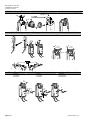
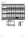
Mounting Position Position de montage Posición de montaje
2A
1A
1
1B
2B
EA0880R1
MANUAL
OVERRIDE
MANUAL
OVERRIDE
EA1045R3
< 45
< 45
90
ASK75.3U
ASK75.3U
IP 54 NEMA 3R
Item Number: 129-307-04, Rev. CA Page 1 of 7

Document No. 129-307
Installation Instructions
January 21, 2013
Limits for Angular Rotation Limites de l’angle de rotation Límites de rotación angular
0
90
90
2
d
1
3
X = steps
X 5
X = 3
0
5
10
15
...
EA1035R1
Shaft Mounting Montage sur l’axe des volets Montaje sobre el eje
f
6
5
2
3
3'
4
4'
1
g
f
EA0884R2
10 mm
7
7'
7.5-9 lb-ft
(10-12 Nm)
7.5-9 lb-ft
(10-12 Nm)
EA0883R2
Manual Override Positionnement manuel Reposición manual
• winding • locking • releasing
• positionner • verrouiller • déverrouiller
• posicionar • enganchar • desenganchar
1
2
3
5
6
7
8
4
HOLD
90º
3 mm
h
x 7-3/4 = 90º
EA0882R2
Page 2 of 7 Siemens Industry, Inc.

Document No. 129-307
Installation Instructions
January 21, 2013
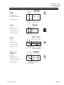
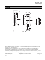
Wiring Diagrams Schémas de raccordement Diagramas de cableado
GMA12x
24 Vac/dc
2-position control
Commande tout ou rien
Control a 2 puntos
M
SWITCH
A
SWITCH
B
DUAL AUXILIARY
SWITCHES
S1
S4
S2 S3 S5 S6
2
1
EA0864R1
NEUTRAL N.C. N.O. N.C. N.O.
COMMON
SUPPLY
COMMON
Class 2
GMA22x
120 Vac
2-position control
Commande tout ou rien
Control a 2 puntos
M
SWITCH
A
SWITCH
B
DUAL AUXILIARY
SWITCHES
S1
S4
S2 S3 S5 S6
4
3
EA0955R1
NEUTRAL N.C. N.O. N.C. N.O.
COMMON
LINE
COMMON
GMA13x
24 Vac/dc
3-position control
Commande 3 points
Control a 3 puntos
M
1000 OHMS
0% 100%
P1
0 TO 100%
P1 TO P2
P3
100 TO 0%
P2 TO P3
P2
COMMON
FEEDBACK POTENTIOMETER
DUAL AUXILIARY SWITCHES
NEUTRALSUPPLY
S2 S1 S3
N.C.CCWCW N.O.
SWITCH A
COMMON
S5 S4 S6
N.C. N.O.
SWITCH B
COMMON
1
6
7
2
EA0873R1
Class 2
GMA15x (2-10V)
GMA16x (0-10V)
24 Vac/dc
Modulating control
Commande progressive
Control continuo
SWITCH
A
SWITCH
B
DUAL AUXILIARY
SWITCHES
S1
S4
S2 S3 S5 S6
EA0867R1
N.C. N.O. N.C. N.O.
COMMON COMMON
M
NEUTRALSUPPLY
OUTPUTINPUT
1
8
9
2
Class 2
Siemens Industry, Inc. Page 3 of 7

Document No. 129-307
Installation Instructions
January 21, 2013
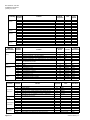
Connecting
Standard
Symbol
Function
Terminal
Designation
Color
Color
Symbol
1 Supply (SP) G Red RD
2 System Neutral G0 Black BK
6 Control signal clockwise Y1 Violet VT
7 Control signal counterclockwise Y2 Orange OG
8 Input Signal: 0-10 Vdc (GMA16x) or 2-10 Vdc (GMA15x) Y Gray GY
24 Vac/dc
Actuator
9 Position Output: 0-10 Vdc (GMA16x) or 2-10 Vdc (GMA15x) U Pink PK
3 Line L Black BK 120 Vac
Actuator
4 Neutral N White WH
S1 Switch A Common Q11 Gray/red GYRD
S2 Switch A N.C. Q12 Gray/blue GYBU
S3 Switch A N.O. Q14 Gray/pink GYPK
S4 Switch B Common Q21 Black/red BKRD
S5 Switch B N.C. Q22 Black/blue BKBU
Auxiliary
Switches
S6 Switch B N.O. Q24 Black/pink BKPK
P1 Feedback Potentiometer 0 to 100% P1 - P2 a White/red WHRD
P2 Feedback Potentiometer Common b White/blue WHBU
Position
indicator
P3 Feedback Potentiometer 100 to 0% P3 - P2 c White/pink WHPK
Câbles de
raccordement
Symbole
Standard
Fonction
Connexion
Bornes
Couleur
Couleur
Abbreviation
1 Alimentation (SP) G Rouge RD
2 Neutre (SN) G0 Noir BK
6 Signal de commande – sens des aiguilles Y1 Violet VT
7 Signal de commande – sens contraire des aiguilles Y2 Orange OG
8 Signal de commande 0…10 V (GMA16x) ou 2…10 V- (GMA15x) Y Gris GY
Servomoteur
24 V~/-
9 Sortie 0 …10 V- (GMA16x) ou 2-10 V- (GMA15x)
pour indicateur de position
U Rose
PK
3 Secteur L Noir BK Servomoteurs
120 V~
4 Neutre N Blanc WH
S1 Commutateur A Commun Q11 Gris/rouge GYRD
S2 Commutateur A N.F. Q12 Gris/bleu GYBU
S3 Commutateur A N.O. Q14 Gris/rose GYPK
S4 Commutateur B Commun Q21 Noir/rouge BKRD
S5 Commutateur B N.F. Q22 Noir/bleu BKBU
commutateurs
auxiliaires
S6 Commutateur B N.O. Q24 Noir/rose BKPK
P1 Potentiomètre réaction 0…100% P1 - P2 a Blanc/rouge WHRD
P2 Potentiomètre réaction Commun b Blanc/bleu WHBU
Indicateur de
position
P3 Potentiomètre réaction 100…0% P3 - P2 c Blanc/rose
WHPK
Conexión
Símbolo
estándar
Función
Terminal
designado
Color
Color
Abreviatura
1 Suministro de corriente (SP) G Rojo RD
2 Sistema neutral G0 Negro BK
6 Señal de control-sentido de las agujas del rejol Y1 Violeta VT
7 Señal de control - sentido contrario a las agujas del reloj Y2 Naranja OG
8 Señal de entrada 0 a 10 V (GMA16x) o 2 a 10V (GMA15x) Y Gris GY
Accionador
24V ca/cc
9 Salida de 0 a 10V cc (GMA16x) o 2 a 10V cc (GMA15x)
para indicador de posición
U Rosado PK
3 Línea L Negro BK Accionador
120V ca
4 Neutro N Blanco WH
S1 Conmutador A Común Q11 Gris/rojo GYRD
S2 Conmutador A N.C. Q12 Gris/azul GYBU
S3 Conmutador A N.A. Q14 Gris/rosado GYPK
S4 Conmutador B Común Q21 Negro/rojo BKRD
S5 Conmutador B N.C. Q22 Negro/azul BKBU
Conmutadores
auxiliares
S6 Conmutador B N.A. Q24 Negro/rosado BKPK
P1 Potenciómetro de realimentación 0 a 100% P1 - P2 a Blanco/rojo WHRD
P2 Potenciómetro de realimentación común b Blanco/azul WHBU
Indicador de
posición
P3 Potenciómetro de realimentación 100 a 0% P3 - P2 c Blanco/rosado WHPK
Page 4 of 7 Siemens Industry, Inc.

Document No. 129-307
Installation Instructions
January 21, 2013
Siemens Industry, Inc. Page 5 of 7
Retrofit Wiring
Siemens
GMA Series
Belimo
LF Series
NF Series
Honeywell
MS7505 Series
Johnson
M9208 Series
Modulating Control
(0 to 10 Vdc)
Function
Color Number Color Number Color Number Color Number
Supply (24V) Red 1 Red 2 Red 1 Red 2
Common Black 2 Black 1 Black 2 Black 1
0(2) to 10 Vdc Input Gray 8 White 3 White 3 Gray 3
0(2) to 10 Vdc Feedback Pink 9 Orange 5 Blue 5 Orange 4
Siemens
GMA Series
Belimo
LF Series
NF Series
Honeywell
MS8105 Series
Johnson
M9208 Series
2-Position Control
(24 Vac/Vdc)
Function
Color Number Color Number Color Number Color Number
Supply (24V) Red 1 Red 2 Red 1 Red 2
Common Black 2 Black 1 Black 2 Black 1
Siemens
GMA Series
Belimo
LF Series
NF Series
Honeywell
MS4105 Series
Johnson
M9208 Series
2-Position Control
(120 Vac)
Function
Color Number Color Number
Terminal
Only
Number Color Number
Line (120V) Black 3 Black 2 1 Black 2
Neutral White 4 White 1 2 White 1
Postcâblage
Siemens
Série GMA
Belimo
Série LF
Série NF
Honeywell
Série MS7505
Johnson
Série M9208
Commande
progressive
(0…10 V-)
Couleur Numéro Couleur Numéro Couleur Numéro Couleur Numéro
Alimentation (24 V) Rouge 1 Rouge 2 Rouge 1 Rouge 2
Commun Noir 2 Noir 1 Noir 2 Noir 1
Entrée 0(2)…10 V- Gris 8 Blanc 3 Blanc 3 Gris 3
Retroaction 0(2)…10 V- Rose 9 Orange 5 Bleu 5 Orange 4
Siemens
Série GMA
Belimo
Série LF
Série NF
Honeywell
Série MS8105
Johnson
Série M9208
Commande TOR
(24 Vac/Vdc)
Couleur Numéro Couleur Numéro Couleur Numéro Couleur Numéro
Alimentation (24 V) Rouge 1 Rouge 2 Rouge 1 Rouge 2
Commun Noir 2 Noir 1 Noir 2 Noir 1
Siemens
Série GMA
Belimo
Série LF
Série NF
Honeywell
Série MS4105
Johnson
Série M9208
Commande TOR
(120 Vac)
Couleur Numéro Couleur Numéro
Terminal
seulement
Numéro Couleur Numéro
Alimentation (120 V) Noir 3 Noir 2 1 Noir 2
Neutre Blanc 4 Blanc 1 2 Blanc 1
La page est en cours de chargement...

Document No. 129-307
Installation Instructions
January 21, 2013
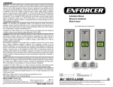
Dimensions
(Continued)
Dimensions Dimensiones
min. 1/2
(12)
5-9/16
(141)
8-3/8
(212)
1-11/16
(42)
1-3/16
(30)
1-3/16
(30)
1/8
(3)
min. 4
(100)
min. 6
(150)
min.2-3/8
(60)
min. 4
(100)
EA0877R2
3 ft
(900)
2-3/8
(60)
1/2" NSPT
1/2
(12)
3/4
(19)
47.5˚ 47.5˚
min. 4
(100)
3.25
(83)
25/32
(20)
7-1/16
(180)
5mm
Ø
EA0876R1
Information in this publication is based on current specifications. The company reserves the right to make changes in specifications and models as design
improvements are introduced. OpenAir is a trademark of Siemens Schweiz, AG. Other product or company names mentioned herein may be the trademarks of
their respective owners. © 2013 Siemens Industry, Inc.
Les informations contenues dans ce document sont basées sur les caractéristiques les plus récentes. Nous nous réservons le droit de modifier ces
caractéristiques, de même que les modèles, à mesure que des évolutions techniques sont introduites. OpenAir est une marque de Siemens Schweiz, AG. Tout
autre nom de produit ou de société mentionné dans ce document peut être la marque de son propriétaire respectif. ©2013 Siemens Industry, Inc.
Este documento ha sido preparado en base a especificaciones actuales. La compañía se reserva el derecho de modificar las especificaciones, así como los
modelos, a medida que se incorporen nuevas mejoras técnicas. OpenAir es marca registrada de Siemens Schweiz, AG. Los nombres de otros productos o
compañías aquí mencionados serán las marcas de sus respectivos propietarios. © 2013 Siemens Industry, Inc.
Siemens Industry, Inc.
Building Technologies Division
1000 Deerfield Parkway
Buffalo Grove, IL 60089-4513
USA
+1-847-215-1000
Your feedback is important to us. If you have
comments about this document, please send them to
sbt_technical[email protected]
Document No. 129-307
Printed in the USA
Page 7 of 7
-
 1
1
-
 2
2
-
 3
3
-
 4
4
-
 5
5
-
 6
6
-
 7
7


Siemens Building Technologies GMA131.1P Guide d'installation
- Taper
- Guide d'installation
- Ce manuel convient également à
dans d''autres langues
Autres documents
-
Siemens GPC166.1P Damper Actuator Manuel utilisateur
-
-
Carel Blast Chiller pCO3 Small Technical Leaflet
-
-
Honeywell N05XX Le manuel du propriétaire
-
sauter AVM 322-R Assembly Instructions
-
OJ Electronics OJ-Zone-Module-M Mode d'emploi
-
ENFORCER SD-7623-GSTQ Guide d'installation
-
SBC PCS1 Le manuel du propriétaire
-
 ENFORCER SD-7103GC-PTQ Guide d'installation
