ATTENTION
IF YOU HAVE ANY PROBLEMS OR QUESTIONS, EMAIL
OR CALL CUSTOMER SERVICE BEFORE YOU RETURN
THIS PRODUCT TO THE STORE WHERE IT WAS PURCHASED.
For Customer Service: email: par[email protected]
in English Call: 866-661-1218
in Spanish Call: 866-661-1218
in French Call: 866-374-9203
ATENCIÓN
SI TIENE ALGÚN PROBLEMA O PREGUNTAS,
ENVÍE UN MENSAJE DE CORREO ELECTRÓNICO O LLAME AL SERVICIO
DE ATENCIÓN AL CLIENTE ANTES DE DEVOLVER
ESTE PRODUCTO A LA TIENDA EN LA QUE LO COMPRÓ.
Servicio de atención al cliente: Correo electrónico: par[email protected]
Línea para llamadas en inglés: 866-661-1218
Línea para llamadas en español: 866-661-1218
Línea para llamadas en francés: 866-374-9203
STOP
STOP
PARE
PARE
ATTENTION
SI VOUS AVEZ DES PROBLÈMES OU QUESTIONS,
ENVOYEZ UN COURRIEL AU SERVICE À LA CLIENTÈLE OU APPELEZ LE
SERVICE À LA CLIENTÈLE AVANT DE RETOURNER
CE PRODUIT OÙ VOUS L’AVEZ ACHETÉ.
Pour le service à la clientèle : courriel : par[email protected]
pour le service en anglais, composez le 866-661-1218
pour le service en espagnol, composez le 866-661-1218
pour le service en français, composez le 866-374-9203
ARRÊT
ARRÊT
INSTRUCTION MANUAL ENCLOSED
MANUEL D’INSTRUCTION À L’INTÉRIEUR
MANUAL DE INSTRUCCIONES ADJUNTO
INSTRUCTION MANUAL ENCLOSED
MANUEL D’INSTRUCTION À L’INTÉRIEUR
MANUAL DE INSTRUCCIONES ADJUNTO

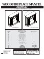
PARTS LIST
PART
A Hearth/Base
B Left Front Panel
C Right Front Panel
D Center Front Panel
E Left Side Panel
F Right Side Panel
G Mantel/Top
P Top Corner Extension
Q “L” Corner Brace
HARDWARE
L
Bolt 1/4” x 1 1/4”
M Washer
N Wood Dowel
E-1
DESCRIPTION
QUANTITY
1
1
1
1
1
1
1
1
1
30+1 extra
30+1 extra
26+1 extra
Z Touch-Up Pen
1
E-mail: [email protected]
In English call: 866-661-1218
In French call: 866-374-9203
In Spanish call: 866-661-1218
For Customer Service:
33445
Wall Mantel
Corner Mantel
ASSEMBLY INSTRUCTIONS
WOOD FIREPLACE MANTEL
23DM537
V1.0

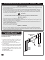
PLEASE READ AND FOLLOW ALL SAFETY TIPS
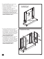
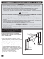
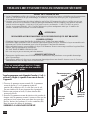
For a complete tight fit every bolt
should have a flat washer.
All panels are labeled Left and Right as viewed
from the front of unit.
1. Locate the Center Front Panel (D), Right Front
Panel (C) and Left Front Panel (B) and set out
face down on a scratch-free surface.
2. Insert one Wood Dowel (N) into each of the
pre-drilled holes.
3. Push the Right Front Panel and Left Front Panel
snug to the Center Panel. Make sure the Wood
Dowels are seated in the pre-drilled holes. Insert
Bolts (L) and Washers (M) into the holes in the
mounting blocks.
HAND TIGHTEN ONLY.
E-2
Center Front
Panel
Left
Front
Panel
Right
Front
Panel
N
N
N
N
C
B
D
L
M
GETTING STARTED
1. Before assembly, carefully use scissors or utility knife to cut and unwrap all parts. Make sure you do
not discard the hardware.
HELPFUL HINTS
6RPHVWHSVDUHPRUHHDVLO\KDQGOHGZLWKWZRDGXOWV
Attach the fireplace insert to the completed wood mantel last. Install insert in from the back of the
fireplace so as not to scratch the hearth/base.
8VHFDUHLQDVVHPEOLQJ\RXUQHZfireplace, take your time and use the hardware provided and a
quality Phillips head screwdriver.
NEVER OVER TIGHTEN BOL76
CARE & CLEANING
1. Dust your fireplace regularly with a soft non-lint producing cloth or household dusting product.
2. You can clean your fireplace with a gentle non-abrasive household cleaner. Make sure to dry your
fireplace immediately with a soft cloth or towel.
2. Make sure that you have all the parts listed. If you are missing any parts please email Customer
6HUYLFHSDUWV#WZLQVWDUKRPHFRPor call 1-866-661-1218 in English, 1-866-374-9203 in French
RULQ6SDQLVK Please identify the parts you need and model number. Make sure
to include your name and address.
'RQRWVLWRQDQ\SDUWRIWKHPDQWHO
CAUTION:
DO NOT MOVE MANTEL OR INSERT WHILE PLUGGED INTO POWER SUPPLY.
V1.0

E-3
A
E
Hearth/Base
Completed Front
Panel Assembly
Completed Assembly
Left
Side
Panel
F
Right
Side
Panel
L
L
M
M
M
N
N
N
N
N
N
N
N
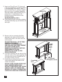
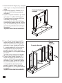
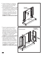
4. Locate Hearth/Base (A) and set out
¿QLVKHGVLGHXSRQWKHÀRRU
,QVHUWRQH:RRG'RZHO1LQWRHDFK
RIWKHSUHGULOOHGKROHV
$WWDFKWKHFRPSOHWHG)URQWSDQHO
DVVHPEO\IURPVWHSWRWKH
Hearth/Base (A). Make sure the dowels
DUHVHDWHGLQWRWKHSUHGULOOHGKROHVLQ
WKH+HDUWK%DVH8VLQJ%ROWV/DQG
:DVKHUV0DWWDFKSDQHOVWKURXJK
SUHGULOOHGKROHVLQWKHPRXQWLQJEORFNV
HAND TIGHTEN ONLY.
/RFDWH/HIW6LGH3DQHO(LQVHUWRQH
:RRG'RZHO1LQWRHDFKRIWKH
SUHGULOOHGKROHV$WWDFKWKH6LGH3DQHO
WR+HDUWK%DVH$DQGWKHFRPSOHWHG
front assembly. Then use Bolts (L) and
:DVKHUV0WKURXJKWKHSUHGULOOHG
KROHVLQWKHPRXQWLQJEORFNV
HAND TIGHTEN ONLY.
/RFDWH5LJKW6LGH3DQHO)LQVHUWRQH
:RRG'RZHO1LQWRHDFKRIWKH
SUHGULOOHGKROHV$WWDFKWKH6LGH3DQHO
WR+HDUWK%DVH$DQGWKHFRPSOHWHG
front assembly. Then use Bolts (L) and
:DVKHUV0WKURXJKWKHSUHGULOOHG
KROHVLQWKHPRXQWLQJEORFNV
HAND TIGHTEN ONLY.
L
V1.0

Completed
Unit
E-4
Install
Insert
From
Back
Electric
Fireplace Insert
11. Remove the two mounting brackets
attached to the back of the Left and
Right Front panels. Set aside with the
wood screws.
12. Lift insert carefully into the back of the
unit and center in the insert opening. Do
not drag insert across Hearth/Base (A)
as it may scratch your unit.
13. Install the mounting brackets to hold
insert flush against the inside of the
mantel front panel.
PLEASE READ ALL “ELECTRIC
FIREPLACE INSERT”
INSTRUCTIONS PRIOR TO
INSTALLING ELECTRIC INSERT
IN YOUR COMPLETED
FIREPLACE MANTEL. INSTALL
THE INSERT IN YOUR
FIREPLACE CLOSE TO ITS
FINAL POSITION.
MOVE YOUR COMPLETED UNIT
ONLY SHORT DISTANCES.
MOVE COMPLETED UNIT WITH
GREAT CARE. IT TAKES TWO
PEOPLE TO MOVE COMPLETED
UNIT INTO ITS FINAL POSITION.
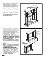
G
N
N
N
N
N
N
N
N
L
M
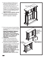
Mantel/Top
Completed
Assembly
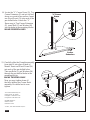
10. Using Phillips head screwdriver tighten
all Bolts alternating top and bottom, left
and right.
9. Insert one Wood Dowel (N) into each
of the pre-drilled holes on the top edges
of the Assembly from step 8. Then
locate Mantel/Top (G) and lay finished
side up on top of completed assembly.
From the inside, attach Mantel/Top (G)
using Bolts (L) and Washers (M)
through the pre-drilled holes in the
mounting blocks.
HAND TIGHTEN ONLY.
V1.0

E-5
Twin-Star International, Inc.
Delray Beach, FL 33445
In English: 1-866-661-1218
In Spanish: 1-866-661-1218
Model# 23DM537
Made in China
Printed in China
© 2010, Twin-Star International, Inc.
N
N
N
N
L
M
L
M
M
L
HAND TIGHTEN ONLY.
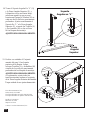
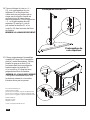
P
Top
Corner
Extension
Q
“L”Corner
Brace
14. Locate the “L” Corner Brace (Q), Top
Corner Extension (P) and set out face
down on a scratch-free surface. Insert
one Wood Dowel (N) into each of the
pre-drilled holes. Attach the “L”
Brace snug to Top Corner Extension
(P), insert Bolt (L) and Washer (M)
into the holes in the mounting blocks.
15. Carefully slide the Complete assembly
from step 14 into place at back of
Mantel. Insert one Wood Dowel (N)
into each of the pre-drilled holes.
Then use Bolts (L) and Washers (M)
through the pre-drillled holes in the
mounting blocks.
HAND TIGHTEN ONLY.
Now you may tighten down all
the bolts holding the Corner Back
assembly. Be careful not to over
tighten.
V1.0

LISTA DE PIEZAS
Pieza
Descripción
Cantidad
PIEZAS
Base Del Hogar
Panel Delantero Izquierdo
Panel Delantero Derecho
Panel Delantero Central
Panel Lateral Izquierdo
Panel Lateral Derecho
Repisa/Parte Supeiror
Tornillo De 1/4” X 1 1/4”
Arandela
Espiga De Madera
30+1 adicional
30+1 adicional
26+1 adicional
S-1
Fabricado en China
Impreso en China
Correo electrónico: [email protected]
Línea para llamadas en inglés: 866-661-1218
Línea para llamadas en francés: 866-374-9203
Línea para llamadas en español: 866-661-1218
Servicio de atención al cliente:
ATENCIÓN
Requiere Un Hogar Eléctrico
Para Chimenea Con Calentador
33445
23DM537
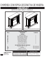
CHIMENEA CON REPISA DECORATIVA DE MADERA
INSTRUCCIONES PARA EL MONTAJE
Repisa De Chimenea De Pared
Repisa De Chimenea De Esquina
P
Q
Pieza Angular Superior
Soporte Angular En "L"
Bolígrafo Para Retocar 1Z
ELEMENTOS PARA EL MONTAJE
V1.0

S-2
LEA TODOS LOS CONSEJOS PRÁCTICOS DE SEGURIDAD
COMIENZO
CONSEJOS PRÁCTICOS
3DUDUHDOL]DUDOJXQRVSDVRVOHUHFRPHQGDPRVTXHVROLFLWHD\XGDDSHUVRQDVDGXOWDV
&RORTXHHOKRJDUHOpFWULFRXQDYH]TXHKD\DWHUPLQDGRGHPRQWDUODUHSLVDGHFRUDWLYDGHPDGHUD
LQVWDOHHOKRJDUHOpFWULFRGHVGHODSDUWHSRVWHULRUGHODFKLPHQHDDILQGHHYLWDUTXHVHGDxHODEDVH
GHOKRJDU
7yPHVHHOWLHPSRQHFHVDULRSDUDDUPDUODFKLPHQHDKiJDORFRQFXLGDGR\XWLOLFHORVHOHPHQWRVGH
PRQWDMHSURYLVWRVDVtFRPRXQGHVWRUQLOODGRU3KLOOLSVGHEXHQDFDOLGDG
/(5(&20(1'$02648(12$-867('(0$6,$'2/267251,//26
1RVHVLHQWHVREUHQLQJXQDSDUWHODUHSLVDGHODFKLPHQHD
CUIDADO Y LIMPIEZA
4XLWHHOSROYRGHODFKLPHQHDGHIRUPDUHJXODUFRQXQSDxRVXDYHTXHQRGHMHSHOXVDRELHQXWLOLFH
XQSURGXFWRGHOLPSLH]D
$VLPLVPRSXHGHDSOLFDUXQOLPSLDGRUQRDEUDVLYR5HFXHUGHVHFDUODFKLPHQHDLQPHGLDWDPHQWHFRQ
XQSDxRRWRDOODVXDYH
1$QWHVGHFRPHQ]DUFRQHOPRQWDMHXWLOLFHODVWLMHUDVRXQDQDYDMDSDUDFRUWDUHOHQYROWRULR&21
08&+2&8,'$'2\DFRQWLQXDFLyQH[WUDLJDWRGDVODVSLH]DV7HQJDFXLGDGRGHQRDUURMDUORV
HOHPHQWRVTXHXWLOL]DUiHQHOPRQWDMHGHODXQLGDG
&RQWUROHTXHHVWpQWRGDVODVSLH]DVGHODOLVWD
6LOHIDOWDDOJXQDSLH]DHQYtHXQPHQVDMHGHFRUUHR
HOHFWUyQLFRROODPHD6HUYLFLRVGHDWHQFLyQDOFOLHQWH3DUWV#WZLQVWDUKRPHFRPROODPHDO
OtQHDHQLQJOpVOtQHDHQIUDQFpVOtQHDHQHVSDxRO
'HVFULEDODVSLH]DVTXHQHFHVLWD\HOQ~PHURGHOPRGHOR1RVHROYLGHGHFRORFDU
VXQRPEUH\GLUHFFLyQ
PRECAUCIÓN:
NO MUEVA LA REPISA NI EL HOGAR MIENTRAS ESTÁN CONECTADOS AL SUMINISTRO DE ENERGÍA.
Panel Delantero
Central
Panel
Delantero
Izquierdo
Panel
Delantero
Derecho
7RPHHO3DQHO'HODQWHUR&HQWUDO'HO3DQHO
'HODQWHUR'HUHFKR&\HO3DQHO'HODQWHUR,]TXLHUGR
%\FROyTXHORVFRQODFDUDKDFLDDEDMRVREUHOD
VXSHUILFLHVLQPDUFDV
,QVHUWHXQD(VSLJD'H0DGHUD1HQFDGDXQRGH
ORVRULILFLRVSUHYLDPHQWHSHUIRUDGRV
$MXVWHFRUUHFWDPHQWHHO3DQHO'HODQWHUR'HUHFKR
\HO3DQHO'HODQWHUR,]TXLHUGRDO3DQHO&HQWUDO
&RPSUXHEHTXHODV(VSLJDV'H0DGHUDHVWpQELHQ
FRORFDGDVHQORVRULILFLRVFRUUHVSRQGLHQWHV,QVHUWH
XQ7RUQLOORV/\XQD$UDQGHODV0HQORV
RULILFLRVGHORVEORTXHVGHPRQWDMH
AJUSTE SÓLO MANUALMENTE.
A fin de que los tornillos queden
debidam ente ajustados, deberá colocarles
una arandela plana.
Si observa la parte delantera de los paneles,
comprobará que en los lados se indica Izquierda
(Left) y Derecha (Right).
V1.0
N
N
N
N
C
B
D
L
M

S-3
Base Del Hogar
Panel
Lateral
Izquierdo
Panel
Lateral
Derecho
Conjunto Delantero
Armado
4. Tome la Base Del Hogar (A) y colóquela
sobre el piso con la parte terminada hacia
arriba.
5. Inserte una Espiga De Madera (N) en
cada uno de los orificios previamente
perforados.
6. Ajuste el conjunto Delantero, que armó
en el paso 3, a la Base Del Hogar (A).
Compruebe que las espigas estén bien
colocadas en los orificios
correspondientes de la Base del Hogar.
Para ajustar los paneles, pase un Tornillos
(L) y una Arandelas (M) por los orificios
previamente perforados de los bloques
de montaje.
AJUSTE SÓLO MANUALMENTE.
8. Tome el Panel Lateral Derecho (F) e
inserte una Espiga De Madera (N) en
cada uno de los orificios previamente
perforados. Luego, coloque un Tornillos
(L) y una Arandelas (M) en los orificios
correspondientes de los bloques de
montaje. Ajuste el Panel Lateral a la
Base Del Hogar (A) y al conjunto delantero
ya armado.
AJUSTE SÓLO MANUALMENTE.
Conjunto Armado
7. Tome el Panel Lateral Izquierdo (E) e
inserte una Espiga De Madera (N) en
cada uno de los orificios previamente
perforados. Luego, coloque un Tornillos
(L) y una Arandelas (M) en los orificios
correspondientes de los bloques de
montaje. Ajuste el Panel Lateral a la
Base Del Hogar (A) y al conjunto delantero
ya armado.
AJUSTE SÓLO MANUALMENTE.
V1.0
E
F
L
L
M
M
N
N
N
N
A
M
N
N
N
N
L

Unidad
Terminada
S-4
Instalar El
Hogar Desde
La Parte
Posterior
Hogar Eléctrico
Para Chimenea
Levante el hogar cuidadosamente,
colóquelo en la parte posterior de la
unidad y céntrelo en la abertura de la
chimenea. No empuje el hogar desde su
Base dado que la unidad se puede dañar.
Coloque los soportes de montaje de
modo que el hogar se encuentre nivelado
con respecto a la parte interior del panel
frontal de la repisa.
11. Quite los dos soportes de montaje fijados
en la parte trasera de los paneles izquierdo
y derecho. Coloque a un lado los tornillos
para madera.
12.
13.
LEA ATENTAMENTE TODAS LAS
INSTRUCCIONES DEL “HOGAR
ELÉCTRICO” ANTES DE SU
INSTALACIÓN EN LA CHIMENEA
DECORATIVA. UBIQUE EL HOGAR
ELÉCTRICO EN LA POSICIÓN
DEFINITIVA DENTRO DE LA
CHIMENEA.
MUEVA LA UNIDAD COMPLETA
SÓLO EN DISTANCIAS CORTAS.
MUEVA LA UNIDAD COMPLETA
CON MUCHO CUIDADO. SE
NECESITAN DOS PERSONAS PARA
DESPLAZAR LA UNIDAD
COMPLETA AL LUGAR
DEFINITIVO QUE VA A OCUPAR.
10. Utilizando un destornillador Phillips
(cruciforme), apriete todos los pernos,
alternando entre la parte superior e
inferior, la izquierda y la derecha.
Conjunto Armado
Repisa/Parte Superior
9. Inserte una Espiga De Madera (N) en
cada uno de los orificios previamente
perforados del borde superior del
Conjunto que armó en el paso 8. Luego,
tome la Repisa/Parte Superior (G) y
colóquela, con el lado acabado hacia
arrinba, sobre el conjunto armado. Desde
el interior, ajuste la Repisa colocando un
Tornillos (L) y una Arandelas (M) en los
orificios previamente perforados de los
bloques de montaje.
APRIETELOS SOLAMENTE A MANO.
G
N
N
N
N
N
N
N
N
L
M
V1.0

S-5
Twin-Star International, Inc.
Delray Beach, FL 33445
Línea para llamadas en inglés: 866-661-1218
Línea para llamadas en español: 866-661-1218
Modelo N° 23DM537
Fabricado en China
Impreso en China
© 2010, Twin-Star International, Inc.
Soporte
Angular en "L"
Pieza
Angular
Superior
AJUSTE SÓLO MANUALMENTE.
A continuación, ajuste todos los
tornillos mientras sostiene el conjunto
de la Pieza Angular Posterior del mueble.
Tenga cuidado de no ajustar demasiado.
AJUSTE SÓLO MANUALMENTE.
15. Deslice con cuidado el Conjunto
armado del paso 14 en la parte
posterior de la Repisa. Luego,
coloque Tornillos (L) y Arandelas (M)
a través de los orificios previamente
perforados de los bloques de montaje.
14. Tome el Soporte Angular En “L” (Q)
y la Pieza Angular Superior (P), y
colóquelos con la cara hacia abajo,
sobre una superficie que no raye.
Inserte una Espiga De Madera (N) en
cada uno de los orificios previamente
perforados. Ajuste correctamente el
Soporte En “L” a la Pieza Angular
Superior (P), e inserte los Tornillo (L)
y las Arandela (M) en los orificios
de los bloques de montaje.
N
N
N
N
L
M
L
M
M
L
P
Q
V1.0

LISTE DES PIÈCES
Pièce Description Quantité
PIÈCES
A Âtre/Base 1
B Panneau avant de gauche 1
C Panneau avant de droite 1
D Panneau avant central 1
L Boulon 1/4” X 1 1/4” 30+1 extra
30+1 extra
M
Rondelle
N Goujon en bois 26+1 extra
Z Crayon pour retouches 1
F-1
Requiert un foyer électrique
encastrable avec chauffage
courriel : [email protected]
pour le service en anglais, composez le 866-661-1218
pour le service en français, composez le 866-374-9203
pour le service en espagnol, composez le 866-661-1218
Pour le service à la clientèle :
Twin-Star International, Inc.
Delray Beach, FL 33445
Fabriqué en Chine
Imprimé en Chine
E Panneau de gauche 1
F
G
Panneau de droite
Manteau/Dessus
1
1
P1
Q1
QUINCAILLERIE
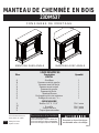
MANTEAU DE CHEMINÉE EN BOIS
23DM537
CONSIGNES DE MONTAGE
MANTEAU SANS ANGLE MANTEAU AVEC ANGLE
Prolongation du coin supérieur
Écharpe de coin en « L »
V1.0

VEUILLEZ LIRE ET SUIVRE TOUS LES CONSEILS DE SÉCURITÉ
F-2
Panneau
avant de
droite
Panneau
avant de
gauche
Panneau avant
central
AVANT DE COMMENCER
1. Avant l’installation, utilisez des ciseaux ou un couteau universel pour couper et déballer tous les composants.
Faites ATTENTION de ne pas endommager le manteau. Assurez-vous de ne pas jeter la quincaillerie
d’installation incluse.
2. Assurez-vous d’avoir toutes les pièces indiquées sur la liste. S'il manque des pièces, veuillez envoyer un
courriel au service à la clientèle à l’adresse
[email protected] ou composez les numéros suivants :
pour le service en anglais : 1-866-661-1218; pour le service en français : 1-866-374-9203 ou pour le
service en espagnol-866-661-1218.
Veuillez indiquer les pièces manquantes ainsi que le numéro de
modèle. Assurez-vous d’inclure vos nom et adresse.
CONSEILS UTILES
&ertaines étapes seront plus faciles à réaliser avec l’aide d’un autre adulte.
La dernière étape consistera à lier le manteau entièrement monté au foyer. installez le foyer encastrable en le
déposant par l’arrière du manteau pour éviter d’égratigner l’âtre/base du manteau.
Faites attention lorsque vous assemblez le foyer et le manteau. 3renez votre temps et utilisez la quincaillerie
fournie, ainsi qu’un tournevis cruciforme.
NE 3AS T5O3 SE55E5 LES %O8LONS.
SOINS ET NETTOYAGE
1.epoussetez régulièrement votre FO<E5 avec un chiffon doux non pelucheux ou un produit domestique
pour l’époussetage.
2.Vous pouvez nettoyer le foyer avec un nettoyant domestique doux non abrasif. Assurez-vous de l’essuyer
immédiatement avec un linge doux ou une serviette.
Ne vous asseyez pas sur aucune partie du manteau.
ATTENTION
NE PAS DÉPLACER LE MANTEAU OU LE FOYER TANT QU’IL EST BRANCHÉ.
1.Trouvez le panneau avant central (D), le panneau
avant de droite (&) et le panneau avant de
gauche (%) et déposez-les, le c{té fini vers le sol,
sur une surface où ils ne pourront être égratignés.
3.3oussez les panneaux avant de droite et de gauche de
chaque c{té du panneau central. Assurez-vous que les
goujons en bois soient bien assis dans les trous pré-
percés. Insérez les boulons (L) et les rondelles (M)
dans les trous des blocs de montage.
SERRER À LA MAIN SEULEMENT.
2.Insérez un goujon en bois (N) dans chacun des
trous pré-percés.
Tous les panneaux sont étiquetés Gauche (« Left »)
et Droit (« Right ») à partir d’une vue de face de
l’appareil.
Pour un assemblage sans jeu, chaque
boulon devrait comporter une rondelle
plate.
V1.0
N
N
N
N
C
B
D
L
M

F-3
Âtre/Base
Panneau
de gauche
Panneau
de droite
Panneau
avant monté
4. Trouvez l’âtre/base (A) et déposez le
côté fini, vers le haut, sur le plancher.
5. Insérez un goujon en bois (N) dans
chacun des trous pré-percés.
6. Fixez le panneau avant, assemblé à l’étape
3, sur l’âtre/base (A). Assurez-vous que
les goujons sont bien assis dans les trous
pré-percés de l’âtre/base. Avec les
boulons (L) et les rondelles (M), fixez
les panneaux en glissant les boulons et
les rondelles dans les trous pré-percés
des blocs de montage.
SERRER À LA MAIN SEULEMENT.
7. Trouvez le panneau de gauche (E) et
insérez un goujon en bois (N) dans
chacun des trous pré-percés. Glissez
ensuite un boulons (L) et une rondelles
(M) dans les trous pré-percés des blocs
de montage. Attachez le panneau latéral
à l’âtre/base (A). Terminez ensuite
l’assemblage de la partie avant.
SERRER À LA MAIN SEULEMENT.
8. Trouvez le panneau de droite (F) et
insérez un goujon en bois (N) dans
chacun des trous pré-percés. Glissez
ensuite un boulons (L) et une rondelles
(M) dans les trous pré-percés des blocs
de montage. Attachez le panneau latéral
à l’âtre/base (A). Terminez ensuite
l’assemblage de la partie avant.
SERRER À LA MAIN SEULEMENT.
Panneau monté
V1.0
E
F
L
L
M
M
N
N
N
N
A
M
N
N
N
N
L

F-4
Installer le
foyer
encastrable
par l’arrière
Foyer encastrable
électrique
Unité
assemblée
11. Retirez les deux brides de montage fixées à
l’arrière des panneaux avant de gauche et de
droite. Mettez-les de côté, avec les vis à bois.
12. Soulevez doucement le foyer encastrable
pour le déposer par l’arrière du manteau,
dans le centre de l’ouverture de celui-ci. Ne
pas tirer le foyer encastrable sur la âtre/base
(A) car cela pourrait égratigner la base du
manteau.
13. Installez les brides de montage pour ainsi
garder le foyer encastrable à égalité avec
l’intérieur du manteau.
VEUILLEZ LIRE TOUTES LES
INSTRUCTIONS D’INSTALLATION
DU FOYER ÉLECTRIQUE
ENCASTRABLE AVANT
D’INSTALLER LE FOYER DANS LE
MANTEAU, UNE FOIS CELUI-CI
ASSEMBLÉ. INSTALLEZ LE FOYER
DANS L’ESPACE PRÉVU, PRÈS DE
SA POSITION FINALE.
NE DÉPLACEZ LE FOYER
ENTIÈREMENT MONTÉ QUE
SUR DE COURTES DISTANCES.
DÉPLACEZ L’UNITÉ MONTÉE
AVEC SOIN. IL FAUT DEUX
PERSONNES POUR DÉPLACER
L’UNITÉ MONTÉE ET LA
METTRE EN PLACE.
Manteau
assemblé
Manteau/Dessus
10. Avec un tournevis cruciforme, serrez tous
les goujons, en alternant entre le haut et le
bas, la gauche et la droite.
9. Insérez un goujon en bois (N) dans chacun
des trous pré-percés de la bordure
supérieure du panneau assemblé à l’étape
8.Trouvez ensuite le manteau/dessus (G).
Déposez le côté fini du manteau sur le
dessus du panneau entièrement monté.
De l’intérieur, fixez le manteau à l’aide
d’un boulons (L) et d’une rondelles (M),
en les insérant dans les trous pré-percés
des blocs de montage.
SERRER À LA MAIN SEULEMENT.
G
N
N
N
N
N
N
N
N
L
M
V1.0

F-5
Twin-Star International, Inc.
Delray Beach, FL 33445
pour le service en anglais, composez le 866-661-1218
pour le service en français, composez le 866-374-9203
pour le service en espagnol, composez le 866-661-1218
Modèle 23DM537
Fabriqué en Chine
Imprimé en Chine
© 2010, Twin-Star International, Inc.
15. Glisser soigneusement l’assemblage
complété à l’étape 14 et le mettre en
place à l’arrière du manteau. Utiliser
ensuite les goujon en bois (N) et
les insérer dans les trous prépercés.
Insérer ensuite les boulons (L)
et les rondelles (M) dans les trous
prépercés des blocs de fixation.
SERRER À LA MAIN SEULEMENT.
Vous pouvez maintenant serrer tous
les boulons retenant le coin arrière.
Attention de ne pas trop serrer.
14. Trouver écharpe de coin en « L »
(Q), et la prolongation du coin
supérieur (P) et les placer face
contre terre sur une surface qui ne
risque pas de s’érafler. Insérer un
goujon en bois (N) dans chacun
des trous prépercés. Unir le support en
« L » et la prolongation du coin
supérieur (P) sans qu’il y ait de
jeu, insérer les boulon (L) et les
rondelle (M) dans les trous des blocs
de fixation.
SERRER À LA MAIN SEULEMENT.
Prolongation du
coin supérieur
Écharpe de coin en «L»
N
N
N
N
L
M
L
M
M
L
P
Q
V1.0
-
 1
1
-
 2
2
-
 3
3
-
 4
4
-
 5
5
-
 6
6
-
 7
7
-
 8
8
-
 9
9
-
 10
10
-
 11
11
-
 12
12
-
 13
13
-
 14
14
-
 15
15
-
 16
16


Twin-Star International 23DM537 Assembly Instructions Manual
- Taper
- Assembly Instructions Manual
- Ce manuel convient également à
dans d''autres langues
- English: Twin-Star International 23DM537
- español: Twin-Star International 23DM537
Documents connexes
-
Twin-Star International 18RM2233 Assembly Instructions Manual
-
-
-
-
-
-
-
-
-