
1
Stagnoli s.r.l. - Via Mantova Traversa 1, 105 a/b
25017 Lonato - Brescia - Italia
tel (+39) 030.9139511 fax (+39) 030.9139580
www.stagnoli.com
IT
EN
FR
Moving Ideas.
ISTRUZIONI LANTERNA SEMAFORICA CHRONOS
CHRONOS
INSTRUCTIONS FEU DE CIRCULATION CHRONOS
INSTRUCTIONS CHRONOS TRAFFIC LIGHT

2
www.stagnoli.com
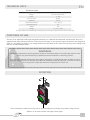
ROTAZIONE
DATI TECNICI
FINALITÀ D’UTILIZZO
AVVERTENZE
Chronos è una lanterna semaforica orientabile progettata esclusivamente per ambiti residenziali e industriali. Poi-
chè è dotato di un’elettronica multitensione, sarà necessario solamente cablare il semaforo (come da schema di
pagina 4). È possibile alimentarlo con tensioni comprese tra i 24 ed i 230V AC/DC senza alcun settaggio della
tensione utilizzata. Chronos è grado d’isolamento IP66.
DATI TECNICI
Corrente max. * 0.028 - 0.1 A
Alimentazione * da 24 a 230 V ac/dc
Potenza * 2 - 5W
Ore di lavoro 50’000
Luminosità 122 Lux
Temperatura operativa -20 / +55 [°C]
Livello di protezione IP 66
Rotazione 180°
Peso 1.5 - 2.5 - 3.5 Kg
* Il dato si riferisce alla singola luce, supponendo che in un semaforo si accende una sola luce alla volta.
L’installazione, la manutenzione ed in particolare l’accesso alle parti interne del semaforo devono
essere svolte solo ed esclusivamente da personale qualicato ed in assenza di corrente.
Questo manuale di istruzioni contiene importanti informazioni riguardanti la sicurezza: leggere atten-
tamente tutte le istruzioni prima di procedere all’installazione. Stagnoli non si assume alcuna respon-
sabilità per danni dovuti ad usi impropri, erronei ed irragionevoli del prodotto. Conservare con cura
questo manuale anche per utilizzi futuri.
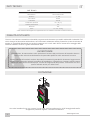
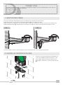
Una volta installato il tutto, per ruotare il corpo sarà sufciente allentare le viti di ssaggio delle staffe.
Scegliere la posizione migliore e serrarle nuovamente.
IT

3
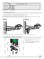
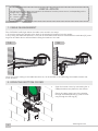
1. PASSAGGIO CAVO
Il semaforo CHRONOS dà la possibilità di far passare il cavo in due modi:
1.A: dal muro all’apertura sul retro della staffa [A] e poi dentro al corpo
1.B: utilizzando l’apposito preforo, praticare un foro sulla staffa, e montare un passacavo standard PG12 [B],
facendo attenzione a montare il pressacavo prima di ssare la staffa al muro
A
B
1.A
1.B
Una volta denito il passaggio del cavo ssare la staffa al muro tramite le apposite viti e tasselli.
INFORMAZIONI UTILI
Le dimensioni del caso variano in base alla distanza dalla sorgente di alimentazione, quindi alla ca-
duta di tensione, Stagnoli consiglia:
00 - 50 mt: 0,5-0,75 mm
50 - 100 mt: 0,75 -1 mm
>100 mt : 1 - 1,5 mm
2. APRIRE COPERCHIO INFERIORE
Aprire il coperchio inferiore svitando le 4 viti a
croce poste sul fondo.
Far passare il cavo che esce dalla staffa at-
traverso l’apposito foro [C] ed eventualemnte
attraverso l’anello OR [D].
D
C

4
www.stagnoli.com
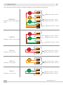
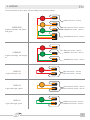
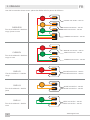
3. CABLAGGIO
ROSSO 24V AC/DC - 230 AC
GIALLO 24V AC/DC - 230 AC
VERDE 24V AC/DC - 230 AC
COMUNE 24V AC/DC - 230 AC
CHR3LRGV
CHR2LRV
CHR1LR
CHR1LG
CHR1LV
ROSSO 24V AC/DC - 230 AC
VERDE 24V AC/DC - 230 AC
COMUNE 24V AC/DC - 230 AC
ROSSO 24V AC/DC - 230 AC
ROSSO 24V AC/DC - 230 AC
GIALLO 24V AC/DC - 230 AC
GIALLO 24V AC/DC - 230 AC
VERDE 24V AC/DC - 230 AC
VERDE 24V AC/DC - 230 AC
Una volta aperto coperchio inferiore eseguire il cablaggio in base al modello di riferimento.
Semaforo a 3 luci, rosso giallo e
verde
Semaforo a 2 luci, rosso e verde
Semaforo a 1 luci, rosso
Semaforo a 1 luci, giallo
Semaforo a 1 luci, verde
IT

5
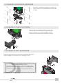
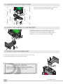
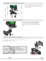
4. CHIUSURA COPERCHIO INFERIORE
6. FISSARE STAFFA SUPERIORE
Fissare la staffa superiore al coperchio ricordandosi di montare
l’anello OR [G] e poi procedere con il ssaggio a muro.
G
Terminato il cablaggio richiudere il coperchio fa-
cendo attenzione al riposizionamento dell’anello
OR [D]
D
5. FISSAGGIO CORPO SU STAFFA
Chiuso il coperchio inferiore ssare il corpo sulla
staffa inferiore, precedentemente ssata (Pag. 3),
tramite l’apposita vite autolettante[E], facendo
attenzione al riposizionamento dell’anello OR [F]
F
E
INFORMAZIONI UTILI
Per avere compelto accesso a tutti e 4 i fori della staffa
superiore sarà sufciente allentare le viti autolettanti sia
superiore che inferiore e ruotare il corpo del semaforo.

X61Axxx REV. 19-04 2019
DICHIARAZIONE DI CONFORMITÀ
Dichiarazione CE: Stagnoli dichiara che questo prodotto è conforme ai requisiti essenziali della direttive
vigenti. Su richiesta è disponibile la copia conforme all’originale della dichiarazione di conformità.
I componenti dell’imballo, cartone o plastiche, possono essere riciclati attraverso la raccolta differenziata.
Nel caso di smaltimento del prodotto invece occorre fare molta attenzione ai componenti che possono con-
tenere sostanze inquinanti quali schede elettroniche, batterie dei radiocomandi etc., che devono essere
recuperati o smaltiti nei centri appositi o presso le ditte autorizzate. In questo caso occorre fare riferimento
alle speciche normative vigenti nel luogo di smaltimento. NON DISPERDERE NELL’AMBIENTE.
Il simbolo del cestino barrato riportato sull’apparecchio indica che il prodotto, alla ne della propria
vita utile, dovendo essere trattato separatamente dai riuti domestici, deve essere conferito in un
centro di raccolta differenziata per apparecchiature elettriche ed elettroniche oppure riconsegnato
al rivenditore al momento dell’acquisto di una nuova apparecchiatura equivalente.
L’utente è responsabile del conferimento dell’apparecchio a ne vita alle appropriate strutture di raccolta.
L’adeguata raccolta differenziata per l’avvio successivo dell’apparecchio dismesso al riciclaggio, al trat-
tamento e allo smaltimento ambientalmente compatibile contribuisce ad evitare possibili effetti negativi
sull’ambiente e sulla salute e favorisce il riciclo dei materiali di cui è composto il prodotto. Per informazioni
più dettagliate inerenti i sistemi di raccolta disponibili, rivolgersi al servizio locale di smaltimento riuti, o al
negozio in cui è stato effettuato l’acquisto.
SMALTIMENTO

7
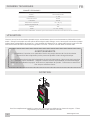
ROTATION
TECHNICAL DATA
PURPOSES OF USE
WARNINGS
Chronos is an adjustable trafc light designed exclusively for residential and industrial environments. Since it is
equipped with multi-voltage electronics, it will only be necessary to wire the trafc light (as shown in the diagram at
page 4). It is possible to supply it at a voltage between 24 and 230V AC/DC without any setting of the voltage used.
Chronos is IP66 insulation class.
TECHNICAL DATA
Electrical current max. * 0.028 - 0.1 A
Voltage * from 24 to 230 V ac/dc
Power * 2 - 5W
Hours of service 50,000
Brightness 122 Lux
Operation temperature -20 / +55 [°C]
IP protection level 66
Rotation 180°
Weight 1.5 - 2.5 - 3.5 Kg
* The gure refers to the individual light, assuming that only one light is switched on at a time in a trafc light.
Installation, maintenance and in particular access to the internal parts of the trafc light must be carri-
ed out only and exclusively by qualied personnel and with no electricity present.
This instruction manual includes important safety information: read all instructions carefully before in-
stallation. Stagnoli does not assume any liability for damage caused by improper, incorrect or unwise
use of the product. Keep this manual in a safe place for future use.
Once completely installed, the body can be rotated simply by loosening the brackets’ xing screws.
Adjust it to the best position and tighten them again.
EN

8
www.stagnoli.com
1. CABLE MANAGEMENT
The CHRONOS trafc light allows the cable to be routed in two ways:
1.A: from the wall to the opening at the back of the bracket [A] and then into the casing
1.B: by using the dedicated pre-hole, cut a hole in the bracket, and mount a standard PG12 cable duct [B], ensu-
ring that the cable duct is mounted before xing the bracket to the wall
A
B
1.A
1.B
Once the correct routing of the cable has been set, x the bracket to the wall using the suitable screws and
screw anchors.
USEFUL ADVICE
The dimensions of the case are based on the distance from the power source, so depending on the
voltage drop, Stagnoli recommends:
00 - 50 mt: 0,5-0,75 mm
50 - 100 mt: 0,75 -1 mm
>100 mt : 1 - 1,5 mm
2. OPEN THE BOTTOM COVER
Open the bottom cover by unscrewing the 4
Phillips head screws placed on the bottom.
Route the cable coming out of the bracket
through the dedicated hole [C] and if neces-
sary through the OR ring [D].
D
C

9
3. WIRING
RED 24V AC/DC - 230 AC
YELLOW 24V AC/DC - 230 AC
GREEN 24V AC/DC - 230 AC
SHARED 24V AC/DC - 230 AC
CHR3LRGV
CHR2LRV
CHR1LR
CHR1LG
CHR1LV
RED 24V AC/DC - 230 AC
GREEN 24V AC/DC - 230 AC
SHARED 24V AC/DC - 230 AC
RED 24V AC/DC - 230 AC
RED 24V AC/DC - 230 AC
YELLOW 24V AC/DC - 230 AC
YELLOW 24V AC/DC - 230 AC
GREEN 24V AC/DC - 230 AC
GREEN 24V AC/DC - 230 AC
Once the bottom cover is open, wire according to the reference pattern
3 lights trafc light, red yellow
and green
2 lights trafc light, red and gre-
en
1 light trafc light, red
1 light trafc light, yellow
1 light trafc light, green
EN

10
www.stagnoli.com
4. CLOSING THE BOTTOM COVER
6. FIXING THE UPPER BRACKET
Fix the upper bracket to the cover being sure to t the OR ring
[G] and then proceed with the xing to the wall.
G
When the wiring is nished, close the cover ensu-
ring that the OR ring is repositioned [D]
D
5. FIXING THE CASING TO THE BRACKET
When the bottom cover is closed, fasten the body
to the lower bracked previously xed (Page 9), by
means of the special self-tapping screw [E], paying
attention to the repositioning of the OR ring [F]
F
E
USEFUL ADVICE
To have complete access to all 4 holes of the upper
bracket, simply loosen the self-tapping screws at the top
and bottom and turn the trafc light casing.

X61Axxx REV. 19-04 2019
DECLARATION OF CONFORMITY
EC Declaration: Stagnoli declares that this product complies with the essential requirements of the directi-
ves in force. A certied copy of the original declaration of conformity is available upon request.
Packaging components, such as cardboard or plastics, can be recycled through separate collection. When
disposing of the product, instead, it is necessary to pay great attention to the components which may con-
tain polluting substances such as electronic boards, remote control batteries, etc., which must be recycled
or disposed of in the designated centres or by authorised companies. In this case, please refer to the speci-
c regulations in force at the location of disposal. DO NOT DISPOSE IN THE ENVIRONMENT.
The crossed-out wheeled bin symbol on the device indicates that the product, at the end of its
useful life, must be treated separately from household waste, must be disposed of at a dedicated
waste collection centre for electrical and electronic equipment or returned to the retailer when
purchasing new equivalent equipment.
The user is responsible for handing over the appliance to the appropriate collection facilities at the end of
its life. Adequate separate collection for subsequent recycling, treatment and environmentally compatible
disposal of the discarded device helps to avoid possible negative effects on the environment and health
and promotes the recycling of the materials of which the product is made. For more detailed information
about the available collection systems, please contact your local waste disposal service or the retailer whe-
re you purchased the product.
DISPOSAL

12
www.stagnoli.com
ROTATION
DONNÉES TECHNIQUES
UTILISATION
AVERTISSEMENTS
Chronos est un feu de circulation ajustable conçu exclusivement pour les environnements résidentiels et indu-
striels. Puisqu’il est équipé avec des pièces électroniques multi-voltages, vous n’aurez qu’à le brancher (comme
indiqué dans le diagramme de la page 4). Il est possible de l’alimenter à un voltage allent de 24 à 230 V AC/DC
sans avoir besoin de faire la moindre conguration à cet effet. Chronos est isolé selon la classe IP66.
DONNÉES TECHNIQUES
Courant électrique max. * 0.028 - 0.1 A
Tension * de 24 à 230 V ac/dc
Puissane * 2 - 5W
Heures de service 50 000
Luminosité 122 Lux
Températures d’opération -20 / +55 [°C]
Niveau de protection IP 66
Rotation 180°
Poids 1.5 - 2.5 - 3.5 Kg
* La valeur réfère à une lumière individuelle, assumant qu’une seule lumière est activée à la fois dans un feu de circulation.
L’installation, l’entretien et en particulier l’accès aux parties internes du feu de circulation
doivent être faits uniquement par du personnel qualié et sans charge électrique.
Ce manuel d’instruction inclus des informations de sécurité importantes : lisez toutes les inscrutions
avec attention avant l’installation. Stagnoli n’assume aucune responsabilité pour des dommages
causés par une utilisation impropre, incorrecte ou imprudente du produit. Conservez ce manuel en
lieu sûr pour référence future.
Une fois complètement installé, le corps peut être tourné en relâchant les visses du support. Faites
l’ajustement puis resserrez les visses à nouveau.
FR

13
1. GESTION DES CÂBLE
Le feu de circulation CHRONOS permet au câble d’être connecté de deux façons :
1.A: depuis le mur via l’ouverture au dos du support [A] et puis dans le boîtier.
1.B: en utilisant en utilisant le trou dessiné dédié, coupez un trou dans le support et montez un conduit pour
câble standard PG12 [B], assurant que le conduit pour câble est monté avant de xer le support au mur.
A
B
1.A
1.B
Un fois le câble en place, xez le support au mur en utilisant les vis et ancrages appropriés.
CONSEIL UTILE
Les dimensions du boîtier sont basées sur la distance depuis la source d’alimentation, alors selon la
baisse de tension, Stagnoli recommande :
00 - 50 m: 0,5-0,75 mm
50 - 100 m: 0,75 -1 mm
>100 m: 1 - 1,5 mm
2. OUVRIR LE COUVERCLE DU BAS
Ouvrez le couvercles du bas en dévissant les
4 vis à tête Phillips situées au-dessous. Pla-
cez le câble venant du support dans le trou
dédié [C] et, au besoin, à travers l’anneau OR
[D].
D
C

14
www.stagnoli.com
3. CÂBLAGE
ROUGE 24V AC/DC - 230 AC
JAUNE 24V AC/DC - 230 AC
VERT 24V AC/DC - 230 AC
COMMUN 24V AC/DC - 230 AC
CHR3LRGV
CHR2LRV
CHR1LR
CHR1LG
CHR1LV
ROUGE 24V AC/DC - 230 AC
VERT 24V AC/DC - 230 AC
COMMUN 24V AC/DC - 230 AC
ROUGE 24V AC/DC - 230 AC
ROUGE 24V AC/DC - 230 AC
JAUNE 24V AC/DC - 230 AC
JAUNE 24V AC/DC - 230 AC
VERT 24V AC/DC - 230 AC
VERT 24V AC/DC - 230 AC
Une fois le couvercle du bas ouvert, placez les câbles selon le patron de référence
Feu de circulation à 3 lumières:
rouge, jaune et verte
Feu de circulation à 2 lumières:
rouge et verte
Feu de circulation à 1 lumière
rouge.
Feu de circulation à 1 lumière
jaune
Feu de circulation à 1 lumière
verte
FR

15
4. FERMER LE COUVERCLE DU BAS
6. FIXER LE SUPPORT SUPÉRIEUR
Fixez le support supérieur au boîtier en étant sûr de placer l’an-
neau OR [G] puis xez-le au mur.
G
Lorsque le câblage est terminé, fermez le couver-
cle en vous assurant que l’anneau OR est bien
repositionné.[D]
D
5. FIXER LE BOÎTIER AU SUPPORT
Lorsque le couvercle du bas est refermé, attachez
le boîtier au support inférieur déjà attaché (page
15), via la vis auto-taraudeuse spéciale [E], en
portant attention au repositionnement de l’anneau
OR [F].
F
E
CONSEIL UTILE
Pour avoir accès complet aux 4 trous du support
supérieur, dévissez légèrement les vis auto-taraudeuse
au-dessus et au-dessous puis tournez le boîtier du feu
de circulation.

Stagnoli s.r.l. - via Mantova Traversa 1, 105 a/b
25017 Lonato - Brescia - Italia
tel (+39) 030.9139511 fax (+39) 030.9139580
www.stagnoli.com
X61A1875 REV. 05 2019
DÉCLARATION DE CONFORMITÉ
Déclaration CE : Stagnoli déclare que ce produit est conforme aux exigences essentielles des directives en
vigueur. Une copie certiée de la déclaration originale de conformité est disponible sur demande.
Les composantes de l’emballage, comme le carton ou les plastiques, peuvent être récupérés via la cueil-
lette sélective. Par contre, lorsque vous vous départissez du produit, vous devez porter attention aux
composantes qui peuvent contenir des substances polluantes comme des circuits électroniques, des piles,
et autres, qui doivent être recyclées et disposées dans des centres désignés ou par des compagnies au-
torisées. Dans ce cas, référez-vous aux règles en vigueur au lieu de disposition. NE PAS EN DISPOSER
DANS L’ENVIRONNEMENT.
Le bac avec un X indique que ce produit, à la n de sa vie utile, doit être traité séparément des
ordures ménagères, il doit être disposé dans un centre de collection de déchets dédié à l’équip-
ement électrique et électronique ou retourné au détaillant lors de l’achat d’un équipement de rem-
placement.
L’usager est responsable de la remise du produit à un centre de collecte approprié à la n de sa vie. Une
collecte sélective adéquate pour recyclage, le traitement et la disposition future de l’appareil conformément
à la protection de l’environnement aide à éviter des effets négatifs possibles sur l’environnement et sur la
santé tout en faisant la promotion du recyclage des matériaux qui composent le produit. Pour plus d’infor-
mations, à propos des systèmes de cueillette disponibles, consultez votre service de déchets local ou le
détaillant où vous avez acheté le produit.
DISPOSITION
-
 1
1
-
 2
2
-
 3
3
-
 4
4
-
 5
5
-
 6
6
-
 7
7
-
 8
8
-
 9
9
-
 10
10
-
 11
11
-
 12
12
-
 13
13
-
 14
14
-
 15
15
-
 16
16


Stagnoli CHR1LR Instructions Manual
- Taper
- Instructions Manual
- Ce manuel convient également à
dans d''autres langues
- italiano: Stagnoli CHR1LR
- English: Stagnoli CHR1LR
Autres documents
-
 RIB PRESIDENT Manuel utilisateur
-
PRESIDENT EP1295992 Installation Instructions Manual
-
BFT RIGEL 5 Installation and User Manual
-
BFT Virgo Smart BT A Manuel utilisateur
-
 RIB AA14041 Manuel utilisateur
-
-
-
-
-

