Eurotherm 2116/2132 Le manuel du propriétaire
- Taper
- Le manuel du propriétaire

2116/2132
PID temperature controllers
User Guide
Manuel Utilisateur
Bedienungsanleitung
ENG
FRA
GER

This booklet includes:
User Guide (HA026270 Issue 5)
Manuel Utilisateur (HA026270FRA Indice 5)
Bedienungsanleitung (HA026270GER Ausgabe 5)

Part Number HA026270 Issue 5.0 Aug 07 1
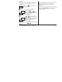
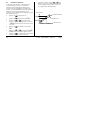
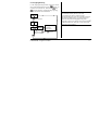
2132 and 2116 PID Temperature Controllers
Thank you for choosing the 2132 or 2116 Temperature Controller. Supplied in 1/32 and 1/16 DIN panel sizes they
are designed for accurate, stable control of ovens, chillers, sterilisers and other heating and cooling processes.
Two outputs are configurable for heating, cooling and alarms.
The controller is supplied configured according to the order code given in section 5. Check this on the side labels
to determine the configuration of your particular controller.
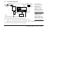
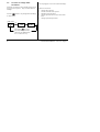
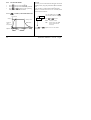
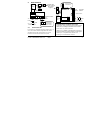
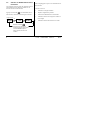
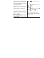
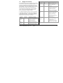
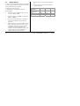
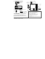
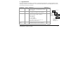
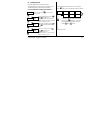
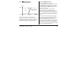
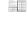
1. Dimensions and Installation
Model 2132
Model 2116
48mm (1.89in)
45 x 45 mm
-0.0, + 0.6
1.77 x 1.77in
-0.00, +0.02
48mm
Panel cut-out
24mm
103mm (4.01in)
45mm
-0.0, +0.6
1.77in
-0.0, +0.02
Latching ears
Panel retaining clips
22mm
-0.0, +0.3
0.88in
-0.0, +0.10
Panel cut-out
103mm (4.01in)
48mm (1.89in)
La page est en cours de chargement...
La page est en cours de chargement...
La page est en cours de chargement...
La page est en cours de chargement...
La page est en cours de chargement...
La page est en cours de chargement...
La page est en cours de chargement...
La page est en cours de chargement...

10 Part Number HA026270 Issue 5.0 Aug 07
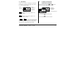
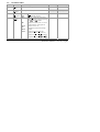
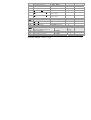
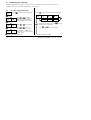
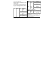
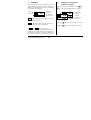
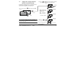
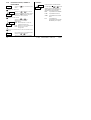
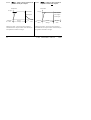
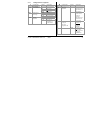
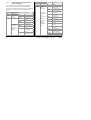
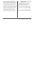
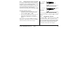
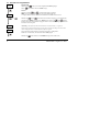
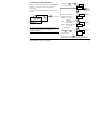
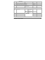
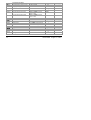
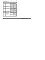
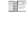
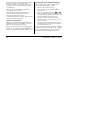
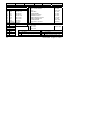
3.8 Parameter Lists
Shaded boxes are hidden when shipped from the factory.
To reveal see ‘’To Hide, Reveal and Promote Parameters” section 3.10
HC.db
Hys.C
HYS.H
Ont.C
Ont.H
OP.Hi
OP.Lo
CJC
O
SPrr
SP H
SP L
AdC
Lb t
HY
diSP
m A
w.SP
Home
List
Alarm
List
Autotune
List
PID
List
(2)
Setpoint
List
Input
List
Output
List
(2)
On/Off
List
Access List
20.0
AL
Atun
Pid
SP
iP
oP
On.Of
ACCS
1---
(1)
2---
(1)
3---
(1)
OP
tunE
Pb
ti
td
rES
Lcb
Hcb
rEL.C
OFS.H
FiLt
mV
OFS
CAL.P
CAL
Pnt.L
OFS.L
Pnt.H
CYC.H
CYC.C
codE
Goto
Conf
tmr
dwel
StAt
tm.OP
(2) Either the PID list or the On/Off list
will be present depending upon the
configuration of the controller.
X2
(1) In place of dashes, the last
three letters depend on the
alarm type.

Part Number HA026270 Issue 5.0 Aug 07 11
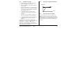
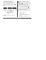
3.8.1 Summary
1. Press
to step across list headings.
2. Press
to step down parameters
3. Press
to view the value of a parameter. Keep pressing to decrease the value.
4. Press
to view the value of a parameter. Keep pressing to increase the value

12 Part Number HA026270 Issue 5.0 Aug 07
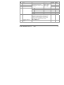
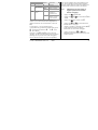
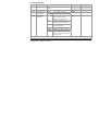
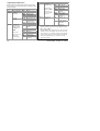
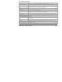
3.9 Parameter Tables
Home List
Adjustable Range Default setting Customer setting
Op
O
utput
P
ower
-100% = max cooling, 100.0% = max heating.
w.SP
W
orking
S
etpoint
Only appears when setpoint rate limit enabled
Read only Read only
m-A
M
anual/
A
uto Select
Auto
mAn
Auto
matic control selected
Man
ual standby selected
Auto
disp
Home
Disp
lay
Options
Std
OP
NonE
PV
AL.SP
pv.aL
St
andard - Shows the process value
with the setpoint accessed by pressing
the
and buttons.
Displays the output power - for use as
a manual station. (Only applies to
software version 1.4)
Blank Display (only alarm messages
flashed)
Displays the P
rocess Value only
Displays the Al
arm 2 Setpoint only
Displays the P
rocess Value with Alarm
2 Setpoint accessed by
and .
Std

Part Number HA026270 Issue 5.0 Aug 07 13
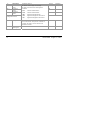
AL
Alarm List (See
section 3.7)
Adjustable
Range
Default
Setting
Customer setting
1---
Alarm 1
Setpoint
0
2---
Alarm 2
Setpoint
0
3---
Alarm 3
Setpoint
In place of dashes, the last
three letters indicate the
alarm type:
Between low
and high
setpoint limits
0
-FSL
F
ull Scale Low
-FSH
F
ull Scale High
-dEv
Dev
iation
-dHi
D
eviation High
-dLo
D
eviation Low
HY
Alarm Hys
teresis 1 to 9999 in display units (This value is
common to all alarms) Hysterisis is used to
prevent the alarm output ‘chattering’ by setting
a difference between the alarm switch ON and
switch OFF points
1
Lb t
L
oop Break Time OFF to 9999 minutes
OFF

14 Part Number HA026270 Issue 5.0 Aug 07
Atun
Automatic Tuning List (See section 4.3)
Adjustable
Range
Default Setting Customer setting
tunE
Automatic Tune
Enable OFF or on
Off
Adc
A
utomatic Manual reset calculation (when P+D
control)
man or
caLc
man
PiD
PID List (See section 4.3) Adjustable Range Default Setting Customer setting
Pb
P
roportional Band 1 to 999.9 display units
20
ti
I
ntegral Time OFF to 9999 seconds
360
td
D
erivative Time OFF to 9999 seconds
60
rES
Manual Res
et Value
(only present if ti= OFF)
-100 to 100.0 %
0.0
Lcb
L
ow Cutback Auto to 999.9 display units
Auto
Hcb
H
igh Cutback Auto to 999.9 display units
Auto
rEL.C
Rel
ative Cool Gain 0.01 to 10.00
1.00

Part Number HA026270 Issue 5.0 Aug 07 15
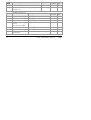
SP
Setpoint List (See also ‘To Use
the Timer’ section 3.11)
Adjustable Range Default Setting Customer setting
SP L
S
etpoint Low Limit -1999 to 999.9 As per order
SP H
S
etpoint High Limit -1999 to 999.9 As per order
sprr
S
etpoint Rate Limit 0FF to 999.9 display units
per minute
Off
tm.OP
T
imer Operating Mode Opt.1 to Opt.5
OPt.1
tmr
T
ime Remaining 0 to 9999 minutes
0
dwEl
Dwell Time 0FF to 9999 minutes
OFF
StAt
Timer Stat
us OFF or on
OFF

16 Part Number HA026270 Issue 5.0 Aug 07
iP
Input List (See also ‘User
Calibration’ section 4.2)
Adjustable Range Default Setting Customer setting
FiLt
Input Filt
er Time Constant 0FF to 999.9 seconds
1.6
CJC
*
C
old Junction Temperature measured at rear terminals Read only
mV
M
illivolt Input measured at the rear terminals Read only
OFS
Process value Of
fset -1999 to 9999 display
units
0
CAL.P
Cal
ibration Password 0 to 9999
3
CAL
User Cal
ibration Enable FACt Re-instates factory
calibration
USEr Re-instates user
calibration
FACt
Pnt.L
L
ow Calibration Point
0
OFS.L
L
ow Point Calibration Offset
0
Pnt.H
H
igh Calibration Point
100
OFS.H
H
igh Point Calibration Offset
-1999 to 9999 display
units
0

Part Number HA026270 Issue 5.0 Aug 07 17
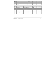
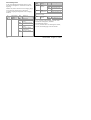
oP
Output List
Adjustable Range Default Setting Customer setting
OP.Lo
Lo
w Output Power Limit -100 to 100.0 %
0
OP.Hi
Hi
gh Output Power Limit -100 to 100.0 %
100.0
CYC.H
H
eating Output Cycle Time 0.2 to 999.9 seconds 1.0 Lgc 20 Rly
CYC.C
C
ooling Output Cycle Time 0.2 to 999.9 seconds 5.0 Lgc 20 Rly
ont.H
H
eating Output Minimum On
T
ime
Auto to 999.9 seconds
(Auto = 50ms)
Auto
ont.C
C
ooling Output Minimum On
T
ime
Auto to 999.9 seconds
(Auto = 50ms)
auto
onOF
On Off Output List
Adjustable Range Default Setting Customer setting
hYS.H
H
eating Hysteresis 1 to 9999 display units
1
hYS.C
C
ooling Hysteresis 1 to 9999 display units
1
HC.db
H
eat/Cool Deadband 0 to 9999 display units
0
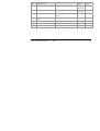
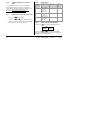
ACCS
Access List (See “To Hide, Reveal and
Promote” parameters section 3.10)
Adjustable Range Default
Setting
Customer setting
codE
Access Pass Number 0 to 9999
1
Goto
Go To Required Access Level Oper, Ful, Edit, conf
OPEr
Conf
Configuration Pass Number
0 to 9999
2
La page est en cours de chargement...
La page est en cours de chargement...
La page est en cours de chargement...
La page est en cours de chargement...
La page est en cours de chargement...
La page est en cours de chargement...
La page est en cours de chargement...
La page est en cours de chargement...
La page est en cours de chargement...
La page est en cours de chargement...

28 Part Number HA026270 Issue 5.0 Aug 07
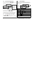
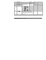
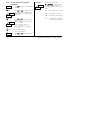
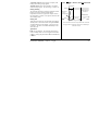
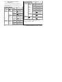
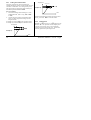
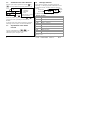
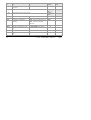
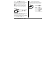
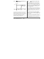
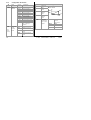
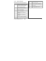
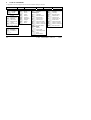
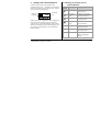
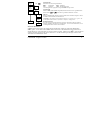
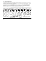
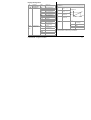
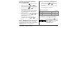
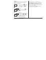
4.1.2 Input Configuration
iP
Sensor
Input
Options Meaning
j.tc
J
thermocouple
k.tc
K
thermocouple
L.tc
L
thermocouple
r.tc
R
thermocouple
b.tc
B
thermocouple
n.tc
N
thermocouple
t.tc
T
thermocouple
S.tc
S
thermocouple
PL 2
P
latinell II
rtd
100Ω PRT
mV
Linear mV
inPt
Inp
ut
t
ype
C.tc
C
ustom input
C=default
Auto
Auto
matic
0*C
0°C external ref.
45*C
45°C external ref.
CJC
(TC
only)
C
old
j
unction
c
ompen
sation
50*C
50°C external ref.
Linear input scaling (Range -12 to +80mV)
InP.L
mV inp
ut
l
ow
InP.H
mV inp
ut
h
igh
VaL.L
Displayed
val
ue low
VAL.H
Displayed
val
ue high
OFF
Off (Linear
inputs only)
Auto
1.5KΩ
Hi
5KΩ
ImP
Sensor
break
input
imp
edance
HiHi
15KΩ,
Inp.L
Inp.H
VAL.H
VAL.L
m
V
Displayed value
La page est en cours de chargement...
La page est en cours de chargement...
La page est en cours de chargement...

32 Part Number HA026270 Issue 5.0 Aug 07
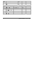
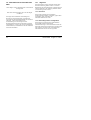
4.1.8 Passwords
PASS
Passwords Range Default
ACC.P
Full and Edit
level password
0-9999 1
CnF.P
C
onfiguration
level p
assword
0-9999 2
CAL.P
User
cal
ibration
p
assword
0-9999 3
4.1.9 To leave Configuration level
Press to reach the ‘exit’ display
Press
or to select ‘YES’ After 2 secs the display
will blink and return to the HOME display in Operator level.
YES
Exit
La page est en cours de chargement...
La page est en cours de chargement...
La page est en cours de chargement...
La page est en cours de chargement...
La page est en cours de chargement...
La page est en cours de chargement...
La page est en cours de chargement...
La page est en cours de chargement...
La page est en cours de chargement...
La page est en cours de chargement...
La page est en cours de chargement...
La page est en cours de chargement...
La page est en cours de chargement...

46 Part Number HA026270 Issue 5.0 Aug 07
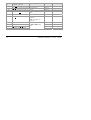
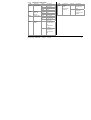
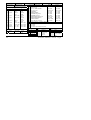
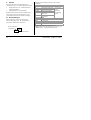
8. RoHS Certificate
Product group
2100
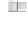
Table listing restricted substances
Chinese
产
2100
铅
镉
铬
溴
联
苯
溴
苯醚
线组
XOX O O O
属
OOO O O O
显
XOO O O O
块
XOX O O O
O
X
English
Product
2100
Pb H
g
Cd Cr
(
VI
)
PBB PBDE
PCBA X O X O O O
Enclosure O O O O O O
Display X O O O O O
Modules X O X O O O
O
X
Approval
Name: Position: Signature: Date:
Martin Greenhalgh Quality Manager
IA029470U450 (CN23172) Issue 1 Feb 07
Indicates that this toxic or hazardous substance contained in at least one of the homogeneous
materials used for this part is above the limit requirement in SJ/T11363-2006.
该质该质
SJ/T11363-2006
标规
Toxic and hazardous substances and elements
Indicates that this toxic or hazardous substance contained in all of the homogeneous materials for
this part is below the limit requirement in SJ/T11363-2006.
Restricted Materials Table
Restriction of Hazardous Substances (RoHS)
览
质
该质该质
SJ/T11363-2006
标规

2116/2132
Régulateurs de Température PID
Manuel Utilisateur
FRA


N
0
Réf HA026270FRA Indice 5.0 08/07 1
2132 et 2116 Régulateurs de Température PID
Merci d'avoir choisi le régulateur de température 2132 ou 2116. Disponibles en formats de panneau 1/32 et 1/16
DIN, ils sont conçus pour une régulation précise et stable des fours, compresseurs frigorifiques, stérilisateurs et
autres procédés de chauffage et de refroidissement. Deux sorties sont configurables pour le chauffage, le
refroidissement et les alarmes.
Ce régulateur est livré configuré selon le code de commande de la paragraphe 5. Regarder sur les étiquettes
latérales pour déterminer la configuration du régulateur
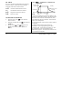
1 Dimensions et Installation
Modèle 2132
Modèle 2116
48mm
45 x 45 mm
-0.0, + 0.6
103mm
48mm
Découpe du
panneau
24mm
48mm 103mm
45mm
-0.0, +0.6
Clips de verrouillage
Clips de fixation
22mm
-0.0, +0.3
Découpe du
panneau

2 N
0
Réf HA026270FRA Indice 5.0 08/07
1.1 Installation du régulateur
Il est conseillé de lire les informations relatives à la sécurité, paragraphe 7, avant de continuer.
1. Préparer la découpe du panneau à la taille indiquée.
2. Insérer le régulateur par la découpe du panneau.
3. Mettre en place les clips de fixation. Immobiliser le régulateur en le tenant horizontal et en poussant les deux
clips de fixation vers l'avant.
4. Retirer le film de protection de la face avant.
1.2 Retrait du régulateur
Il est possible de retirer le régulateur de son manchon en tirant les clips de verrouillage vers l'extérieur et en le
sortant du manchon. Lorsqu'on replace le régulateur dans son manchon, il faut veiller à ce que les clips de
verrouillage s'encliquètent afin que l'étanchéité IP65 soit assurée.
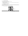
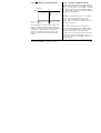
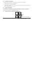
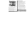
1.3 Espace minimal recommandé entre régulateurs
38mm
10mm
(Cette figure n'est pas à l'échelle)

N
0
Réf HA026270FRA Indice 5.0 08/07 3
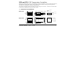
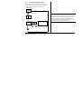
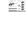
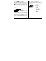
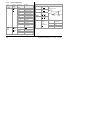
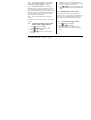
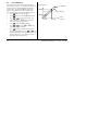
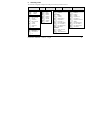
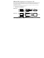
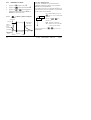
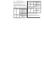
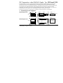
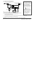
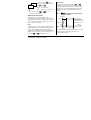
2 Branchements
2.1 Section des fils
Les bornes à vis acceptent des fils de section 0,5 à 1,5
mm². Des caches articulés empêchent tout contact
accidental avec les fils sous tension. Les vis des
bornes arrière doivent être serrées à 0,4 Nm
Caractéristiques nominales des sorties
Sortie logique : 9 Vdc, 12 mA (pas isolée de l'entrée capteur).
Utilisée pour : le chauffage, le refroidissement ou les alarmes.
Sortie relais : 2 A, 264 V ac résistive.
Utilisée pour : le chauffage, le refroidissement ou les alarmes.
Entrée de fermeture des contacts (remplace la sortie logique).
Utilisée pour : l'acquittement des alarmes ou le
démarrage et la réinitialisation du time
r
.
Modèle 2116
OU
+
-
Ligne
Neutre
Sortie 2 Relais
T/C Pt100 mA
Entrées capteurs
L
N
A
AB
V+
V
-
1A
1B
2,49Ω
85-264Vac
50/60Hz
1B 1A
Pt100
T/C
Sortie 2
Relais
Neutre
Ligne
E/S Logiques
Modèle 2132
Module relais
externe (actionné
par la sortie
logique)
OU
Contac-
teur
statique
(SSR)
2,49Ω
Entrées capteu
r
s
AB
V+
V
-
A
LN
+
-
mA
85-264Vac 50/60Hz
1B 1A
Contac-
teur
statique
(SSR)
+ -
E/S Logiques
+
-
20-29 Vac/dc
Alimentation
basse tension
24
24
20-29 Vac/dc
Alimentation
basse tension
24
24

4 N
0
Réf HA026270FRA Indice 5.0 08/07
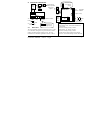
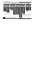
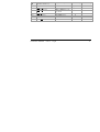
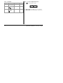
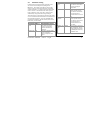
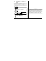
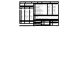
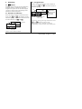
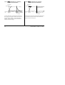
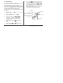
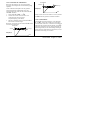
2.2 Schéma de Câblage Type
Conditions de sécurité pour les équipements connectés en permanence :
• Un interrupteur ou disjoncteur sera inclus dans l'installation
• Il devra être situé à proximité de l'équipement et à portée de l'opérateur.
• Il sera clairement identifié comme dispositif de sectionnement de l'équipement
* En cas de commutation
de charges conductrices
comme les contacteurs ou
les électrovannes,
brancher un RC de 22
nF/100 Ω fourni entre les
bornes AA & AB, ce qui
prolonge la durée de vie
des contacts et diminue les
interférences
ATTENTION
Le RC laisse passer 0,6
mA à 110 V et 1,2 mA à
230 Vac, ce qui peut être
suffisant pour maintenir
les charges d'impédance
élevée. Ne pas utiliser
dans ces installations.
Fusible de
la sortie
relais
2A type T
Neutre
Fusible du
régulateuer
2A type T
Fusible pour le chauffage
Chauffage
Thermocouple
Contacteur
statique
(par exemple
(e.g. TE10)
Circuit RC*
Ligne
Modèle 2132
A
V+
1B
V
-
1A
A
L
N
Relais de refroidissement
ou d'alarme
Interrupteur
La page est en cours de chargement...
La page est en cours de chargement...
La page est en cours de chargement...
La page est en cours de chargement...
La page est en cours de chargement...
La page est en cours de chargement...
La page est en cours de chargement...
La page est en cours de chargement...
La page est en cours de chargement...
La page est en cours de chargement...
La page est en cours de chargement...
La page est en cours de chargement...
La page est en cours de chargement...
La page est en cours de chargement...
La page est en cours de chargement...
La page est en cours de chargement...
La page est en cours de chargement...
La page est en cours de chargement...
La page est en cours de chargement...
La page est en cours de chargement...
La page est en cours de chargement...
La page est en cours de chargement...
La page est en cours de chargement...
La page est en cours de chargement...
La page est en cours de chargement...
La page est en cours de chargement...
La page est en cours de chargement...
La page est en cours de chargement...
La page est en cours de chargement...
La page est en cours de chargement...
La page est en cours de chargement...
La page est en cours de chargement...
La page est en cours de chargement...
La page est en cours de chargement...
La page est en cours de chargement...
La page est en cours de chargement...
La page est en cours de chargement...
La page est en cours de chargement...
La page est en cours de chargement...
La page est en cours de chargement...
La page est en cours de chargement...
La page est en cours de chargement...
La page est en cours de chargement...
La page est en cours de chargement...
La page est en cours de chargement...
La page est en cours de chargement...
La page est en cours de chargement...
La page est en cours de chargement...
La page est en cours de chargement...
La page est en cours de chargement...
La page est en cours de chargement...
La page est en cours de chargement...
La page est en cours de chargement...
La page est en cours de chargement...
La page est en cours de chargement...
La page est en cours de chargement...
La page est en cours de chargement...
La page est en cours de chargement...
La page est en cours de chargement...
La page est en cours de chargement...
La page est en cours de chargement...
La page est en cours de chargement...
La page est en cours de chargement...
La page est en cours de chargement...
La page est en cours de chargement...
La page est en cours de chargement...
La page est en cours de chargement...
La page est en cours de chargement...
La page est en cours de chargement...
La page est en cours de chargement...
La page est en cours de chargement...
La page est en cours de chargement...
La page est en cours de chargement...
La page est en cours de chargement...
La page est en cours de chargement...
La page est en cours de chargement...
La page est en cours de chargement...
La page est en cours de chargement...
La page est en cours de chargement...
La page est en cours de chargement...
La page est en cours de chargement...
La page est en cours de chargement...
La page est en cours de chargement...
La page est en cours de chargement...
La page est en cours de chargement...
La page est en cours de chargement...
La page est en cours de chargement...
La page est en cours de chargement...
La page est en cours de chargement...
La page est en cours de chargement...
La page est en cours de chargement...
La page est en cours de chargement...
La page est en cours de chargement...
La page est en cours de chargement...
La page est en cours de chargement...
La page est en cours de chargement...
La page est en cours de chargement...
La page est en cours de chargement...
La page est en cours de chargement...
La page est en cours de chargement...
La page est en cours de chargement...
La page est en cours de chargement...
-
 1
1
-
 2
2
-
 3
3
-
 4
4
-
 5
5
-
 6
6
-
 7
7
-
 8
8
-
 9
9
-
 10
10
-
 11
11
-
 12
12
-
 13
13
-
 14
14
-
 15
15
-
 16
16
-
 17
17
-
 18
18
-
 19
19
-
 20
20
-
 21
21
-
 22
22
-
 23
23
-
 24
24
-
 25
25
-
 26
26
-
 27
27
-
 28
28
-
 29
29
-
 30
30
-
 31
31
-
 32
32
-
 33
33
-
 34
34
-
 35
35
-
 36
36
-
 37
37
-
 38
38
-
 39
39
-
 40
40
-
 41
41
-
 42
42
-
 43
43
-
 44
44
-
 45
45
-
 46
46
-
 47
47
-
 48
48
-
 49
49
-
 50
50
-
 51
51
-
 52
52
-
 53
53
-
 54
54
-
 55
55
-
 56
56
-
 57
57
-
 58
58
-
 59
59
-
 60
60
-
 61
61
-
 62
62
-
 63
63
-
 64
64
-
 65
65
-
 66
66
-
 67
67
-
 68
68
-
 69
69
-
 70
70
-
 71
71
-
 72
72
-
 73
73
-
 74
74
-
 75
75
-
 76
76
-
 77
77
-
 78
78
-
 79
79
-
 80
80
-
 81
81
-
 82
82
-
 83
83
-
 84
84
-
 85
85
-
 86
86
-
 87
87
-
 88
88
-
 89
89
-
 90
90
-
 91
91
-
 92
92
-
 93
93
-
 94
94
-
 95
95
-
 96
96
-
 97
97
-
 98
98
-
 99
99
-
 100
100
-
 101
101
-
 102
102
-
 103
103
-
 104
104
-
 105
105
-
 106
106
-
 107
107
-
 108
108
-
 109
109
-
 110
110
-
 111
111
-
 112
112
-
 113
113
-
 114
114
-
 115
115
-
 116
116
-
 117
117
-
 118
118
-
 119
119
-
 120
120
-
 121
121
-
 122
122
-
 123
123
-
 124
124
-
 125
125
-
 126
126
-
 127
127
-
 128
128
-
 129
129
-
 130
130
-
 131
131
-
 132
132
-
 133
133
-
 134
134
-
 135
135
-
 136
136
-
 137
137
-
 138
138
-
 139
139
-
 140
140
-
 141
141
-
 142
142
-
 143
143
-
 144
144
-
 145
145
-
 146
146
-
 147
147
-
 148
148
-
 149
149
-
 150
150
-
 151
151
-
 152
152
-
 153
153
-
 154
154
-
 155
155
-
 156
156


Eurotherm 2116/2132 Le manuel du propriétaire
- Taper
- Le manuel du propriétaire
dans d''autres langues
- English: Eurotherm 2116/2132 Owner's manual
- Deutsch: Eurotherm 2116/2132 Bedienungsanleitung
Documents connexes
-
Eurotherm 2108i Guide d'installation
-
-
-
-
-
-
-
-
-
Autres documents
-
Shinko MCM-100 Manuel utilisateur
-
-
LG ARWN168DAS4.AWGBLUS Guide d'installation
-
Ascon tecnologic M1 Le manuel du propriétaire
-
CARLO GAVAZZI UA 30 CLD Manuel utilisateur
-
-
 Cashmaster CN142 Series Le manuel du propriétaire
-
LG ARWN200LAS4.EWGBLEU Guide d'installation
-
Omega CN243 Series Le manuel du propriétaire
-
Pacific Track PT10 Manuel utilisateur
