GE ZIF301NPNII Guide d'installation
- Catégorie
- Frigos
- Taper
- Guide d'installation
Ce manuel convient également à

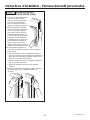
INSTALLATION
INSTRUCTIONS
18”, 24” and 30” Built-In Column Freezers
24” and 30” Built-In Column Refrigerators
ENGLISH/FRANÇAIS/ESPAÑOL.
MONOGRAM.COM

2
31-1000190 Rev. 4
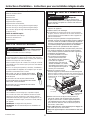
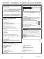
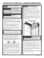
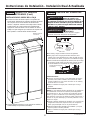
BEFORE YOU BEGIN
Read these instructions completely and carefully.
•
IMPORTANT – Save these instructions for
local inspector’s use. Observe all governing codes and
ordinances.
•
Note to Installer – Be sure to leave these
instructions with the Consumer.
• Note to Consumer – Keep these instructions with
your Owner’s Manual for future reference.
If you received a damaged unit, you should immediately
contact your dealer or builder.
Skill Level – Installation of this unit requires basic
mechanical, carpentry and plumbing skills. Proper
installation is the responsibility of the installer. Product
failure due to improper installation is not covered under
the Monogram Warranty. See the Owner’s Manual for
warranty information.
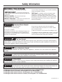
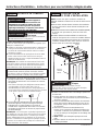
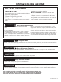
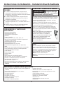
Safety Information
For Monogram local service in your area, visit monogram.com or call 800.444.1845.
For Monogram service in Canada, visit monogram.ca or call 800.561.3344.
For Monogram Parts and Accessories, visit monogram.com or call 800.444.1845.
For Monogram Parts and Accessories in Canada, visit monogram.ca or call 800.661.1616.
WARNING
Tip Over Hazard.
These appliances are top heavy, especially with any doors open, and must be secured to prevent tipping
forward which could result in death or serious injury. Read and follow the entire installation instructions for
securing the appliance with the anti-tip system.
WARNING
Fire or Explosion Hazard.
Keep flammable materials and vapors away from appliance. Failure to do so can result in fire, explosion,
or death.
WARNING
To reduce the risk associated with choking, do not allow children under 3 years of age to
have access to small parts during the installation of this product.
CAUTION
Lifting Hazard
This unit is very heavy. To reduce the risk of person injury during maneuvering and installing this appliance,
3 people are required for proper installation.
CAUTION
Keep fingers out of the “pinch point” areas; clearances between the doors and between the
doors and cabinet are necessarily small. Be careful closing doors when children are in the area.
WARNING
Electrical Shock Hazard.
Plug into a grounded 3-prong outlet.
Do not remove the ground prong.
Do not use an adapter.
Immediately discontinue use of a damaged supply cord.
If the supply cord is damaged it must be replaced by a
qualified service professional with an authorized service
part from the manufacturer.
Do not use an extension cord with this appliance.
Failure to follow these instructions can result in death,
fire, or electrical shock.
Follow the instructions in the section Grounding the unit.
This appliance must be installed with a means in the fixed
house wiring or circuit breaker for disconnecting the appli-
ance from the electrical supply after installation.

3
31-1000190 Rev. 4
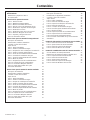
Contents
Safety 2
Design Guide
Dimensions and Clearances 4
Accessories/Kits 5
Reversing the Door Swing 6
Step 1. Remove Upper Enclosure 7
Step 2. Remove Door 7
Step 3. Move Control Assembly 8
Step 4. Move Light Switch Housing 8
Step 5. Reinstall Hinge Brackets 9
Step 6. Reinstall the Enclosure 9
Step 7. Reinstall the Front Access Cover 10
Step 8. Remove Hinges from Door 10
Step 9. Panel Brackets and Hinges 11
Step 10. Reinstall the Door 11
Instructions for Dual Integrated Installation 12
The Installation Space 13
Tools, Hardware, Materials 14
Grounding the Unit 15
Flooring 15
Step 1. Remove Packaging 15
Step 2. Install Water Line 16
Step 3. Preparing Unit for Installation 16
Step 4. Install Anti-tip Bracket 17
Step 5. Joining Dual Installed Units 18
Step 6. Connecting Water Supply 19
Step 7. Inserting/Securing into Cabinet Surround 19
Step 8. Level Unit 20
Step 9. Final External Unit Preparation 21
Step 10. Toe Kick Installation 22
Step 11. Internal Unit Preparation 22
Step 12. Start Icemaker 22
Step 13. Install AutoFill Pitcher Assembly 23
Instructions for Dual Retro-Fit Installation 24
The Installation Space 25
Tools, Hardware, Materials 26
Grounding the Unit 26
Flooring 26
Step 1. Remove Packaging 27
Step 2. Install Water Line 27
Step 3. Preparing Unit for Installation 28
Step 4. Install Anti-tip Bracket 29
Step 5. Joining Dual Installed Units 30
Step 6. Connecting Water Supply 32
Step 7. Inserting/Securing into Cabinet Surround 33
Step 8. Level Unit 34
Step 9. Final External Unit Preparation 34
Step 10. Toe Kick Installation 36
Step 11. Internal Unit Preparation 36
Step 12. Start Icemaker 36
Step 13. Install AutoFill Pitcher Assembly 37
Instructions for Single Integrated Installation 38
The Installation Space 39
Tools, Hardware, Materials 40
Grounding the Unit 40
Flooring 40
Step 1. Remove Packaging 41
Step 2. Install Water Line 41
Step 3. Preparing Unit for Installation 42
Step 4. Install Anti-tip Bracket 42
Step 5. Connecting Water Supply 42
Step 6. Inserting/Securing into Cabinet Surround 43
Step 7. Level Unit 44
Step 8. Final External Unit Preparation 44
Step 9. Toe Kick Installation 45
Step 10. Internal Unit Preparation 45
Step 11. Start Icemaker 45
Step 12. Install AutoFill Pitcher Assembly 46
Stainless Steel Door Panel Installation 47
Step 1. Install Stainless Panel 48
Step 2. Adjust Stainless Panel 49
Step 3. Install Hinge Covers 49
Step 4. Install Door Trims 50
Custom Overlay Door Panel Installation 51
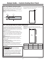
Custom Handle Design Guide 52
3/4” Custom Decorative Panel Dimensions 52
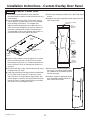
Step 1. Overlay Panel Prep 53
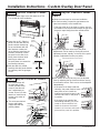
Step 2. Install Overlay Panel 54
Step 3. Adjust Overlay Panel 54
Step 4. Install Hinge Covers 55
Step 5. Install Door Trims 55

4
31-1000190 Rev. 4
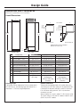
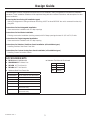
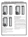
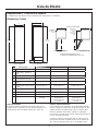
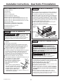
Design Guide
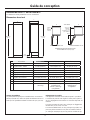
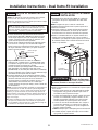
DIMENSIONS AND CLEARANCES
Dimensions in parentheses are in centimeters.
Product Clearances
These units are equipped with a 2-position door stop.
The factory set 115° door swing can be adjusted to 90°
if clearance to adjacent cabinets or walls is restricted.
For a 90° door swing, allow 4” (10.2 cm) minimum
clearance to a wall.
When installed in a corner, allow 15” (38.1 cm) for a full
115° door swing on 18” and 24” models. Allow 16 9/16”
(42.07 cm) on 30” models.
Shipping height.
The product can be adjusted to fit into a cutout that is
84” (213.36 cm). Use leveling legs and wheels for a
maximum 1” (2.54 cm) height adjustment.
Overall Dimensions
FRONT VIEW SIDE VIEW
83-3/8"
(211.77)
C
83-1/4"
(211.46)
A
D
4"
(10.16)
TOP VIEWS
DOOR OPEN 90
DIMENSIONS BASED ON HANDLE
HEIGHT OF 2-9/16” (6.5)
Û DOOR OPEN 115Û
E
F
B
5-1/8"
(13.0)
Minimum
to a Wall
B
15"
(38.1)
Minimum
to a Wall
(16-9/16"
(42.1)
on 30” models)
Dimensions 18” Models 24” Models 30” Models
A Overall Width - Front 17-1/2” (44.5 cm) 23-1/2” (59.7 cm) 29-1/2” (74.9 cm)
B Overall Width - Rear 17-1/4” (43.8 cm) 23-1/4” (59.1 cm) 29-1/4” (74.3 cm)
C Overall Depth 24-3/4” (62.9 cm) 24-3/4” (62.9 cm) 24-3/4” (62.9 cm)
D Case Depth 22-1/16” (56 cm) 22-1/16” (56 cm) 22-1/16” (56 cm)
E Door Clearance at 90° 21-1/4” (53.9 cm) 27-1/4” (62.9 cm) 33-1/4” (84.5 cm)
F Door Clearance at 115° 19-1/16” (48.4 cm) 24-1/2” (62.2 cm) 29-15/16” (76.0 cm)
Cutout Width 17-13/16” (45.3 cm) 23-13/16” (60.5 cm) 29-13/16” (75.7 cm)
Cutout Height 84” (213.4 cm) 84” (213.4 cm) 84” (213.4 cm)
Cutout Depth 25” (63.5 cm) 25” (63.5 cm) 25” (63.5 cm)
Weight 370 lbs
(167.8 kg)
460 lbs (208.7 kg)
(Refrigerator)
430 lbs. (195.0 kg)
(Freezer)
495 lbs (224.5 kg)
(Refrigerator)
475 lbs. (215.5 kg)
(Freezer)

5
31-1000190 Rev. 4
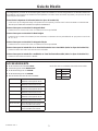
Design Guide
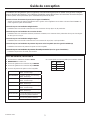
7KH0RQRJUDP&ROXPQVUHIULJHUDWRUVDQGIUHH]HUVFDQEHLQVWDOOHGLQPDQ\FRQ¿JXUDWLRQVZLWKGLႇHUHQWLQVWDOODWLRQ
situations. Three installation situations will be explained along with door reversal instructions and two options for door
panel installation.
Reversing the Door Swing (all installation types)
Making a refrigerator LH swing and freezer RH swing. MUST be done BEFORE the unit is removed from the ship-
ping skid.
Instructions for Dual Integrated Installation
New construction installation with 25” deep openings
Instructions for Dual Retro Installation
Existing construction installation (existing cutouts) with 24” deep openings that are 41-1/2” or 47-1/2” wide
Instructions for Single Integrated Installation
New construction installation with 25” deep opening
Instructions for Stainless Steel Door Panel Installation (all installation types)
Installing Stainless Steel Door Panel Kits
Instructions for Custom Overlay Door Panel Installation (all installation types)
Installing Custom Decorative Panels
ACCESSORIES/KITS
Ŷ ZKUN+HDWHU8QL¿FDWLRQ.LW
Ŷ WX08X10006 8 Ft. Water Line
Ŷ ZKR42N 42” Trim Retro Kit
Ŷ ZKR48N 48” Trim Retro Kit
Ŷ 6WDLQOHVV6WHHO'RRU3DQHO.LWV
Ŷ 6WDLQOHVV7RH.LFNVIRU'XDO,QVWDOO
ZK1SN189NLH LH 18” Stainless Steel Door Panel
ZK1SN184NRH RH 18” Stainless Steel Door Panel
ZK1SN249NLH LH 24” Stainless Steel Door Panel
ZK1SN244NRH RH 24” Stainless Steel Door Panel
ZK1SN309NLH LH 30” Stainless Steel Door Panel
ZK1SN304NRH RH 30” Stainless Steel Door Panel
ZKSP1H1CNSS Minimalist Handle for Stainless
Steel Panels Only
ZKSP1H1PNSS Statement Handle for Stainless
Steel Panels Only
42” ZKK42P
48” ZKK48P
54” ZKK54P
60” ZKK60P

6
31-1000190 Rev. 4
Reversing the Door Swing
This step can be done for all installation types.

7
31-1000190 Rev. 4
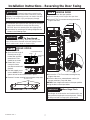
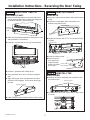
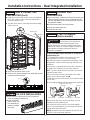
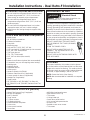
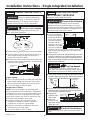
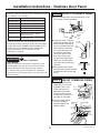
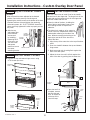
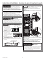
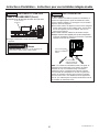
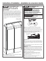
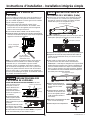
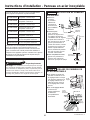
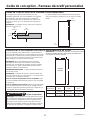
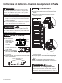
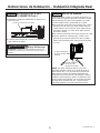
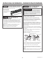
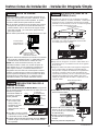
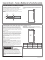
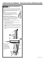
Installation Instructions - Reversing the Door Swing
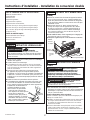
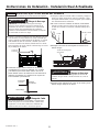
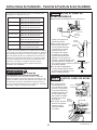
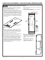
STEP 2 REMOVE DOOR
Ŷ Open the door to the open position.
Ŷ Have a second person support the open door.
Ŷ Remove 2 T30 Torx screws securing the bottom
hinge to the case.
Ŷ Remove the 2 T30 Torx screws securing the top
hinge to the case.
Ŷ Place the door on a protected work surface (to
prevent scratches), liner side down.
NOTICE: Door hinges will remain in the open position
during the door reversal procedure.
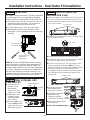
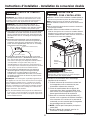
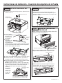
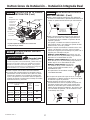
STEP 1 REMOVE UPPER
ENCLOSURE
Ŷ Open the front cover of
the enclosure to 90°.
Locate filter and filter
removal tool. Filter
should be as shown.
Ŷ5RWDWH¿OWHUóWXUQ
counterclockwise
XVH¿OWHUUHPRYDOWRROLI
needed).
Ŷ3XOO¿OWHUWRZDUG\RXWR
remove. NOTE: Water
V\VWHPZLOOQRWIXQFWLRQZLWKRXW¿OWHULQSODFH
Ŷ Remove 6 screws securing front enclosure to top case.
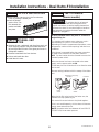
WARNING
Follow all steps when reversing the
door swing. Failure to follow these instructions, leaving
off parts, or overtightening screws, can lead to the door
falling off and result in injury and property damage.
WARNING
Door Hinge Pinch
Point Hazard
Door hinges are under tension and should be left in the
open position throughout the reversal process. Closing
the hinge can lead to a finger pinch point hazard.
Ŷ If installation will require the door swing to be reversed,
follow these directions to reverse the door swing
BEFORE the unit is removed from the shipping skid.
Ŷ Instructions for reversing a RH swing refrigerator are
shown in the following steps.
WARNING
Tip Over Hazard.
This appliance is top heavy, especially with the door
open, and must be secured to prevent tipping forward
which could result in death or serious injury.
Screws
Screws
1/4” Hex Screws
Filter Removal Tool
Filter
Mounting
Hook
Compartment Door

8
31-1000190 Rev. 4
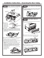
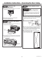
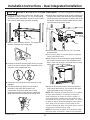
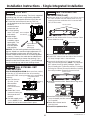
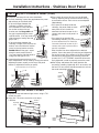
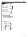
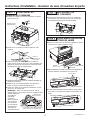
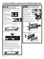
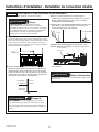
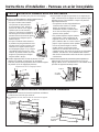
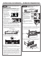
Installation Instructions - Reversing the Door Swing
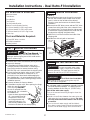
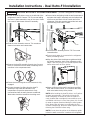
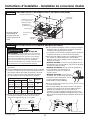
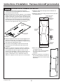
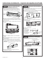
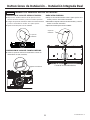
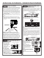
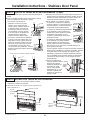
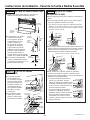
STEP 3
MOVE CONTROL ASSEMBLY
Ŷ Remove upper hinge brackets by removing the T-30
Torx screws.
Ŷ Remove the
Phillips head
screw from the
middle of the
housing on the
hinge side.
Ŷ Insert a flat head screwdriver or putty knife between
the glass front and plastic side and free the control
assembly by prying the plastic pins clear of the side
bracket holes.
Ŷ Lay the glass assembly on top of the control housing.
Ŷ Remove 4 screws, 2 on each end, to remove the
housing assembly using a 1/4” Hex bit.
Ŷ Move the housing assembly to the opposite side and
install using the 4 screws, 2 on each side.
NOTE: Make sure wires do not get pinched. On 18”
models, the red/white/black 5-pin wire connector
will need to be removed from the control board and
routed through the opposite corner bracket and
reconnected to the
control board to
prevent pinching
the wiring.
STEP 3
MOVE CONTROL ASSEMBLY
(Cont.)
Ŷ Snap glass assembly back onto the control housing
assembly, ensuring plastic pins snap into holes on
the side of the housing.
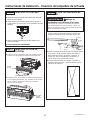
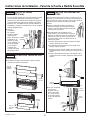
STEP 4 MOVE LIGHT SWITCH
HOUSING
Ŷ Remove front access cover from unit by removing
two 1/4” hex head screws.
Ŷ Remove the Philip screw first and lower hinge
brackets by removing three T-30 Torx screws.
Ŷ Remove screw with 1/4” hex bit driver at the bottom
corner of light switch housing.
Plastic Pins
(Both sides)
Screw
5-pin wire connector
Wires must be rerouted from one
side to the other for 18” models.
Access Cover
1/4” Hex Head
Screws
Upper Hinge
Bracket
T-30 Torx screws
Phillips Screw
T-30 Torx Screws
Phillips Screw
Light Switch

9
31-1000190 Rev. 4
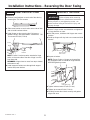
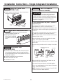
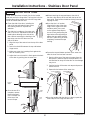
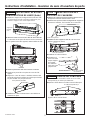
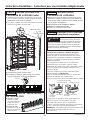
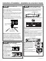
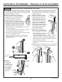
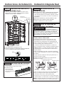
Installation Instructions - Reversing the Door Swing
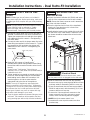
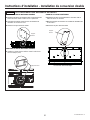
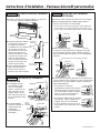
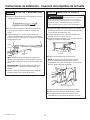
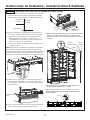
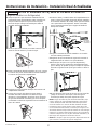
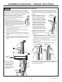
STEP 5 REINSTALL HINGE
BRACKETS
Ŷ Move top hinge bracket to bottom and bottom bracket
to top.
Ŷ Ensure the 2 rectangular slots of bracket are on
outside, hinge side of case.
Ŷ Install both brackets with 3 T-30 Torx screws 45 in/lb
(5.1 Nm).
Ŷ Install the Phillips screw.
Ŷ Start 2 screws in
each bracket for
hinge mounting
but do not tighten
all the way.
STEP 6 REINSTALL THE
ENCLOSURE
Ŷ Install the enclosure assembly with removed six 1/4”
hex head screws.
Ŷ
Locate blue arrow on filter. Rotate filter to align arrow
as shown.
Rectangular
Slots
Screws for
Hinge Brackets
Housing Key Holes
STEP 4 MOVE LIGHT SWITCH
HOUSING (Cont.)
Ŷ Move the mounting bracket to the other side of the
unit by removing two Philips screws and using them
to install the bracket in its new location.
Ŷ Slide housing forward and down to remove from case
and grommets on case bottom.
Ŷ Keeping it connected to the unit, lay housing aside.
Ŷ Remove 2 grommets with Phillips driver.
Ŷ Move grommets to the set of 2 holes on opposite
side.
Ŷ Align housing key holes over grommets and then
slide back until engaged. Ensure wires do not get
pinched.
Ŷ Install Phillips screw into bottom hole to hold in place.
Grommets
Mounting
Bracket and
Screws
Phillips Screw
1/4” Hex Screws

10
31-1000190 Rev. 4
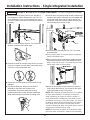
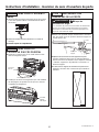
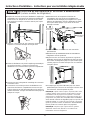
Installation Instructions - Reversing the Door Swing
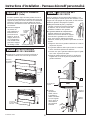
STEP 8 REMOVE HINGES FROM
DOOR
Ŷ Remove 3 screws securing each hinge from the top
and bottom of the door and one screw securing the
support bracket to the door (T-30 Torx)
Ŷ Move the hinge assembly to the opposite end of the
door - top hinge to the bottom and bottom hinge to
the top. Hinge, L-bracket already attached to hinge,
and support bracket will all move together.
Ŷ 2 shims between the hinge bracket and door will
be moved to the other side -
save for installing the hinge.
WARNING
Door Hinge Pinch
Point Hazard
Door hinges are under tension and should be left in
the open position throughout the reversal process.
Closing the hinge can lead to a finger pinch point
hazard.
Hinge
Support
Bracket
Shims
STEP 6 REINSTALL THE
ENCLOSURE (Cont.)
Ŷ,QVHUW¿OWHULQWRSRVLWLRQDQGURWDWHóWXUQFORFNZLVH
XVH¿OWHUUHPRYDOWRROLIQHHGHG
Ŷ5HWXUQ¿OWHUUHPRYDOWRROWRPRXQWLQJKRRN
Ŷ
Close the compartment door.
STEP 7 REINSTALL THE FRONT
ACCESS COVER
Ŷ Put the access cover back onto the unit and secure
with two 1/4” hex head screws.
Ŷ Verify the two 1/4” hex head screws are assembled
to handle side of the products for both freezer and
fresh food columns.
1/4” Hex Screws
Access
Cover
1/4” Hex
Screws

11
31-1000190 Rev. 4
Installation Instructions - Reversing the Door Swing
STEP 9 PANEL BRACKETS AND
HINGES
Ŷ Remove panel brackets on each end of the door by
removing the T30 Torx screws.
Ŷ Slide same bracket on each end to other side of door
and re-install brackets to door.
Ŷ Install hinges to door ensuring that 2 shims are
between hinge L-bracket and door. Install with 3 T-30
Torx screws 45 in/lb (5.1 Nm)
NOTE: Ensure L-bracket remains attached to hinge
and is on the outer side of the door. Hinge is on the
inner door side.
REMINDER: Hinges have to move from top to bottom
and bottom to top.
Ŷ Install support bracket screw through both support
bracket and panel bracket.
STEP 10 REINSTALL THE DOOR
Ŷ Ensure 2 hinge screws are started but not tightened
in hinge brackets on case.
Ŷ With 2nd person, hold door with hinges near correct
position.
Ŷ Install top hinges with key hole over screws and slide
bracket.
Ŷ Repeat on bottom.
NOTE: Ensure 2 tabs on hinges are inserted into
the rectangular slots on outside of hinge brackets
BEFORE tightening screws.
Ŷ Tighten bottom screws 45 in/lb (5.1 Nm).
Ŷ Tighten top screws 45 in/lb (5.1 Nm).
Ŷ Carefully ensure door closes correctly and gasket
aligns with case.
WARNING
Follow all steps when reversing
the door swing. Failure to follow these instructions,
leaving off parts, or overtightening screws, can
lead to the door falling off and result in injury and
property damage.
Hinge
Support
Bracket
Shims
Tabs in
rectangular slots
Key hole slot
over screws

12
31-1000190 Rev. 4
Instructions for Dual Integrated Installation
New construction installation with 25” deep openings

13
31-1000190 Rev. 4
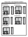
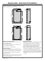
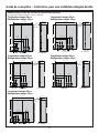
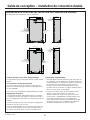
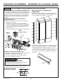
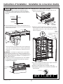
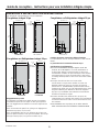
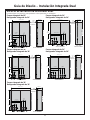
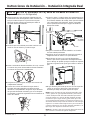
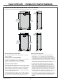
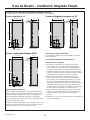
Design Guide - Dual Integrated Installation
18” Integrated Freezer
24” Integrated Refrigerator
30” Integrated Freezer
30” Integrated Refrigerator
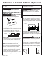
DUAL INTEGRATED INSTALLATION SPACE
Dimensions in parentheses are in centimeters.
FRONT VIEW
84"
(213.4)
41 1/2" (105.4)
E
W
7 1/2”
(19.1)
4"
(10.2)
6"
(15.24)
6"
(15.24)
2 1/2"
(6.4)
3 1/2"
(8.9)
4 1/8"
(10.5)
2"
(5.1)
ELEC W
4"
(10.2)
2 1/2"
(6.4)
5"
(12.7)
22 1/8" (56.2)
27 1/4"
(69.2)
SIDE VIEW
25" (63.5)
3 1/2"
(8.9)
Finished
Return
Back
FRONT VIEW
84"
(213.4)
47 1/2"
(120.7)
E
W
7 1/2"
(19.1)
4"
(10.2)
2 1/2"
(6.4)
2 1/2"
(6.4)
3 1/2"
(8.9)
4 1/8"
(10.5)
2"
(5.1)
ELEC W
6 1/4"
(10.2)
5"
(12.7)
22 1/8" (56.2)
28" (71.1)
SIDE VIEW
25" (63.5)
3 1/2"
(8.9)
Finished
Return
Back
6"
(15.24)
6"
(15.24)
FRONT VIEW
84"
(213.4)
47 1/2"
(120.7)
ELEC W
9 1/2"
(24.1)
4
4 3/8"
(11.1)
ELEC W
4"
(10.2)
2 1/2"
(6.4)
2 1/2"
(6.4)
5"
(12.7)
5"
(12.7)
28 1/8" (71.4)
33 1/4" (84.5)
SIDE VIEW
25" (63.5)
3 1/2"
(8.9)
Finished
Return
Back
6"
(15.24)
6"
(15.24)
84"
FRONT VIEW
84"
(213.4)
53 1/2" (134.6)
ELEC W
9 1/2"
(24.1)
4"
(10.2)
4 3/8"
(11.1)
ELEC W
6 1/4"
(15.9)
2 1/2"
(6.4)
5"
(12.7)
2 1/2"
(6.4)
5"
(12.7)
28 1/8" (71.4)
34" (86.4)
25
SIDE VIEW
25" (63.5)
3 1/2"
(8.9)
Finished
Return
Back
6"
(15.24)
6"
(15.24)
84"
FRONT VIEW
84"
(213.4)
59 1/2" (151.3)
ELEC W
9 1/2"
(24.1)
4"
(10.2)
4 3/8"
(11.1)
ELEC W
6 1/4"
(15.9)
2 1/2"
(6.4)
5"
(12.7)
2 1/2"
(6.4)
5"
(12.7)
34 1/8" (86.67)
40" (101.6)
25
SIDE VIEW
25" (63.5)
3 1/2"
(8.9)
Finished
Return
Back
6"
(15.24)
6"
(15.24)
18” Integrated Freezer
30” Integrated Refrigerator
24” Integrated Freezer
24” Integrated Refrigerator
24” Integrated Freezer
30” Integrated Refrigerator

14
31-1000190 Rev. 4
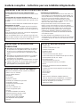
Design Guide - Dual Integrated Installation
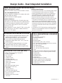
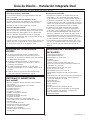
DUAL INTEGRATED INSTALLATION SPACE
Water And Electrical Locations
Electrical and water supply must be located as shown.
The Cutout Depth Must Be 25”
Cutout is based on installation of 2 products with a left-
and-right hand door swing.
Heater Unification Kit ZKUN required.
Product Clearances
These units are equipped with a 2-position door stop.
The factory set 115° door swing can be adjusted to 90°
if clearance to adjacent cabinets or walls is restricted.
For a 90° door swing, allow 4” (10.2 cm) minimum
clearance to a wall.
When installed in a corner, allow 15” (38.1 cm) for a full
115° door swing on 18” and 24” models. Allow 16.5”
(41.9 cm) on 30” models.
Additional Specifications
• A separate 115 volt 60Hz., 15 or 20 amp power supply
is recommended for each product. An individual
properly grounded branch circuit or circuit breaker is
recommended. Install a properly grounded 3-prong
electrical receptacle recessed into the back wall.
Electrical must be located on rear wall as shown.
• Water line must be located on the back wall as shown.
The water line should be 1/4” O.D. copper tubing or
QuickConnect
™
kit (WX08X10006) between the cold
water line and water connection location, long enough
to extend to the front of the unit (8’ [2.4m]). Installation
of an easily accessible shut-off valve in the water line
is required.
• A minimum of 3-1/2” finished return matching cabinet
exterior is recommended on interior on all sides and
top at front of opening.
TOOLS AND MATERIALS REQUIRED
• Metal shears
• #1, #2 Phillips screwdriver
• Flathead screwdriver
• Putty knife
• Measuring tape
• Drill and 1/16”, 5/64”, 3/16”, 1/2” bits
• 5/32” concrete bit (if installing anti-tip into concrete)
• 1/4”, 3/8”, 7/16” driver/socket
• 7/16” open wrench
• T10, T20, T30 driver/bit
• 1/8”, 1/4” hex driver (allen wrench)
• Level
• Water shut-off valves (optional but recommended)
• 8’ waterline (one per unit requiring water hookup)
• Masking tape
• Rubbing alcohol
• Adjustable wrench
• Center punch
• Heater Unification Kit (ZKUN)
• Stainless Steel Door Kits (if applicable)
• Custom panels for doors (if applicable)
• Handle Kits (if applicable)
• Small Ratchet
REFRIGERATOR/FREEZER LOCATION
Ŷ Do not install the refrigerator/freezer where the tem-
perature will go below 55°F (13°C). It will not run
often enough to maintain proper temperatures.
Ŷ Do not install the refrigerator/freezer where
temperatures will go above 100°F (37°C). It will not
perform properly.
Ŷ Do not install the refrigerator/freezer in a location
exposed to water (rain, etc.) or direct sunlight.
Ŷ Install it on a floor strong enough to support it fully
loaded.
HARDWARE SUPPLIED (per unit)
• Water Filter Bypass Plug (if equipped)
• Air filter (if equipped)
• Anti-Tip bracket
• 3 Lag screws
• 3 Tapcon screws
• 3 Toggles with bolts
• Panel installation templates
• 2 Door trims
• 2 Door panel brackets
• Set screws
• #6 Phillips head wood screws
• Door Bracket Cover Top
• T30 screws
• 1 Hinge limiter pin
• Center door panel bracket
• Hi-Lo screw and square washer
• Stainless Toe Kick
• Painted access cover screws
• T10 screw

15
31-1000190 Rev. 4
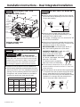
Installation Instructions - Dual Integrated Installation
FLOORING
For proper installation, this product must be placed
on a level surface of hard material that is at the same
height as the rest of the flooring. This surface should
be strong enough to support a fully loaded refrigerator
or freezer, or approximately 1,200 lbs. per unit.
NOTE: Protect the finish of the flooring.
NOTE: Not recommended for installation on carpeted
flooring.
GROUNDING THE UNIT
The power cord of this appliance is equipped with a
3-prong (grounding) plug which mates with a standard
3-prong (grounding) wall receptacle to minimize the
possibility of electric shock hazard from this appliance.
Have the wall outlet and circuit checked by a qualified
electrician to make sure the outlet is properly grounded.
Where a standard 2-prong wall outlet is encountered, it
is your personal responsibility and obligation to have it
replaced with a properly grounded 3-prong wall outlet.
DO NOT, UNDER ANY CIRCUMSTANCES, CUT OR
REMOVE THE THIRD (GROUND) PRONG
FROM THE POWER CORD.
DO NOT USE AN ADAPTER PLUG TO
CONNECT THE REFRIGERATOR TO A
2-PRONG OUTLET.
DO NOT USE AN EXTENSION CORD
WITH THIS APPLIANCE.
WARNING
Electrical Shock
Hazard. Failure to follow these instructions can
result in death, fire, or electrical shock.
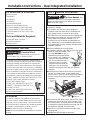
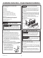
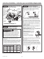
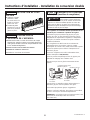
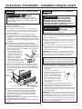
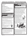
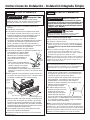
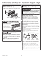
STEP 1 REMOVE PACKAGING
Ŷ Remove outer carton and external packing from units.
Ŷ Inspect for damage.
Ŷ If installation will require the door swing to be
reversed, follow the instructions in Reversing the
Door Swing section to reverse the door swing
BEFORE the unit is removed from the shipping skid.
Ŷ Ensure the flooring that the units are set is clean/
free of debris that could be collected on to, or
pinched in front of the wheels and damaging the
floor. Additionally, it is recommended that the floor
be protected with a plastic covering through out the
installation process.
Ŷ Remove hardware kit from top drawer.
Ŷ If installation requires a 90° door opening, the hinge
limiter pin must be installed in the
top hinge BEFORE the unit is
removed from the shipping skid.
Pin is located in the hardware kit.
- Open the door approximately
45°, but no wider than 90°, to
expose the hole in the back
hinge bracket and install the
limiting pin. Pin must be fully
seated in the bracket or the door will not close
properly.
Ŷ Remove front access cover from unit by removing
two 1/4” hex head screws. (Some models have
access cover in a box on the left side of the cabinet.)
Place the cover and screws to the side for future
installation.
Ŷ Remove three 3/8” drive screws and two 7/16” drive
screws from each side of the unit to release it from
the shipping skid. Tip the unit from the side enough
to remove the shipping material from under the unit,
but above the shipping skid (both sides)
Ŷ CAREFULLY roll the unit off the back side of the
shipping skid.
Ŷ Handle from side only with a hand truck.
Shipping
Bracket
7/16” Drive
Screws
3/8” Drive
Screws
1/4” Hex Head
Screws
Top
Hinge
WARNING
Tip Over Hazard. This
appliance is top heavy. Use extreme caution with
moving to prevent tipping over which could result in
death or serious injury.
KIT ZKUN PARTS SUPPLIED:
Adhesive Heater
Transformer
Front Mullion
Trim Bracket
Top Unification Bracket
Bottom Front Unification Bracket
3 1/4” Hex Head 8-18 5/8” Long Screws
5 1/4” Hex Head 8-32 5/8” Long Screws
5 3/8” Hex Head 1/4-20 1/2” Long Screws
4 wire clips
Tools and Materials Required:
1/4” and 3/8” driver / sockets
#2 Phillips screwdriver
Rubbing alcohol

16
31-1000190 Rev. 4
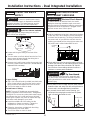
Installation Instructions - Dual Integrated Installation
STEP 2 INSTALL WATER LINE
Shut off the main water supply.
Turn on the nearest faucet long enough to clear the
line of water.
ŶInstall a shut-off valve between the water valve and
cold water pipe in a basement or cabinet. The shut-
off valve should be located where it will be easily
accessible.
ŶTurn on the main water supply and flush debris.
Run about a quart of water through the tubing into a
bucket. Shut off water supply at the shut-off valve.
NOTE: Saddle type shut-off valves are included in
many water supply kits. Before purchasing, make sure
a saddle type valve complies with your local plumbing
codes.
NOTE: Commonwealth of Massachusetts Plumbing
Codes 248CMR shall be adhered to. Saddle
valves are illegal and use is not permitted in
Massachusetts. Consult with your licensed plumber.
Ŷ Route 1/4” OD copper or SmartConnect
™
(WX08X10006) plastic tubing between house cold
water line and the water connection location at the
front of the unit.
SmartConnect
™
Refrigerator Tubing Kits are
available. One 8’ (2.4m) water line (WX08X10006) is
needed for each unit. The waterline(s) will be taped
to the floor using masking tape after anti-tip bracket
installation.
Ŷ Tubing should be long enough to extend to the front
of the unit. Allow enough tubing to accommodate
bend leading into the water line connection. Unit
must be tipped on its side to route waterline
underneath and to the front of the appliance.
NOTE: The only GE Appliances approved plastic
tubing is supplied in the SmartConnect
™
Refrigerator
Tubing kits. Do not use any other plastic water supply
line because the line is under pressure at all times.
Other types of plastic may crack or rupture with age
and cause water damage to your home.
WARNING
Connect to potable water supply
only. A cold water supply is required for automatic
icemaker operation. The water pressure must be
between 40 and 120 psi (275-827 kilopascals).
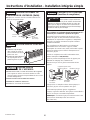
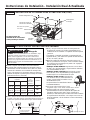
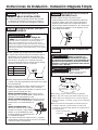
STEP 3 PREPARING UNIT FOR
INSTALLATION
Ŷ Unpack the heater Unification Kit (ZKUN) and make
sure all of the components on the list are included.
NOTE: Ensure the heater connector cord is toward the
top of the unit when installed.
Ŷ Place the right hand unit in front of the installation
opening in a way that the unit is in front of the
intended installed location.
Ŷ Install adhesive heater on the outside of the unit to
the left side of the case. Install heater 4” below the
case top. Heater should be centered front to back on
the metal case.
Ŷ Install the transformer into the case top assembly:
1. Remove cover top by removing eight #8 hex screws
and keep aside for assembling back the cover top.
2. Place the transformer into the case top provided in
ZKUN kit and secure it with the existing (1/4”) hex
screws to left front of case top.
3. Connect the 2 pin transformer connector to the
heater connector and 3 pin connector to panel
control, make sure locking tabs are engaged.
4. NOTE: Verify the master switch is on.
5. Assemble the cover top with screws save from
previous step.
WARNING
ELECTRIC SHOCK HAZARD
Attach tubing clamp using existing hole only. DO
NOT drill into the refrigerator.
Clips
Adhesive
Heater
WARNING
Electrical Shock
Hazard. To avoid the risk of electric shock, make
sure the power cord is not plugged into the wall outlet.
4”

17
31-1000190 Rev. 4
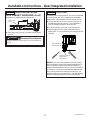
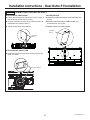
STEP 3 PREPARING UNIT FOR
INSTALLATION (Cont.)
Installation Instructions - Dual Integrated Installation
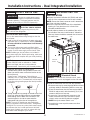
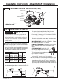
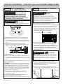
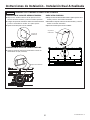
STEP 4
INSTALL ANTI-TIP BRACKET
(Cont.)
Ŷ Measure and mark from the RH side of the opening
per the table above depending on the size of the RH
unit you are installing.
Ŷ Measure and mark again from the RH side of
the opening per the table and depending on your
combination of LH and RH units.
For example, if installing an 18” LH unit and a 30” RH
unit, use 5-3/4” and 38-5/8”.
Ŷ Mount the anti-tip bracket centered about the marks
and flush to the floor as shown. Mark 3 holes for wall
mounting or 4 holes for floor mounting.
WOOD MOUNTING: Predrill with 3/16” drill bit, 2”
deep, then install lag bolts with a 7/16” driver.
CONCRETE MOUNTING: Predrill with a 5/32”
concrete bit, 2” deep, then install
tapcon screws with a 7/16” driver.
STEEL MOUNTING: Predrill with a
1/2” drill bit, insert toggle, then install
bolts with a 7/16” driver.
The bracket must be screwed to
either the FLOOR or REAR WALL.
Ŷ If the enclosure is deeper than 25 ½”, the anti-tip
bracket should be secured to the floor 25” from front
of the enclosure.
Ŷ Tape the waterline to the wall and floor approximately
3” to the left of the anti-tip bracket. Apply tape about
every 5” toward the front of the opening (tape will
prevent the unit from rolling over the waterline during
installation). Do not tape near the cabinet front in
order to keep tape hidden under the unit.
LH Unit
RH Unit
WARNING
Tip Over Hazard.
These appliances are top heavy, especially with any
doors open, and must be secured to prevent tipping
forward which could result in death or serious injury.
Read and follow the entire installation instructions
for securing the appliance with the anti-tip system.
3"
5"
3"
5"
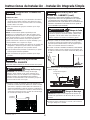
STEP 4
INSTALL ANTI-TIP BRACKET
Ŷ Remove the anti-tip bracket from the hardware kit.
Ŷ Anti-tip bracket should be mounted against the back
wall or up to 25-1/2” (64.7 cm) maximum from front of
opening. Use floor mounting method if the bracket is
not against a wall (bracket hardware is provided for
mounting into wood, steel studs and concrete).
LH Unit
RH UNIT
18” 24” 30”
26-5/8”
67.6 cm
23-1/2”
59.7 cm
23-1/2”
59.7 cm
8-7/8”
22.5 CM
18”
32-5/8”
82.8 cm
29-1/2”
74.9 cm
29-1/2”
74.9 cm
5-3/4”
14.5 CM
24”
38-5/8”
98.1 cm
35-1/2”
90.1 cm
35-1/2”
90.1 cm
5-3/4”
14.5 CM
30”
Enclosure assembly upper
is hidden for clarity.
Do NOT
Remove Wire
Standoff
2 Pin
Connector
to Heater
Connector
3 Pin
Connector
Transformer
Master Switch
#8 Hex
Screws
Cover Top

18
31-1000190 Rev. 4
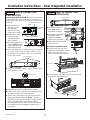
Installation Instructions - Dual Integrated Installation
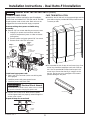
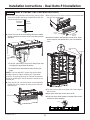
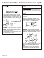
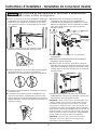
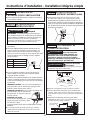
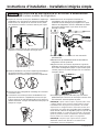
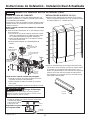
STEP 5
JOINING DUAL INSTALLED UNITS
BOTTOM BACK UNIFICATION
Ŷ Loosen the two bottom screws of rear access covers of
both units and remove the top screws.
Ŷ Hang the unification bracket to the bottom screws and
reassemble the screws at the top
Ŷ Tighten screws to tie units together.
BOTTOM FRONT UNIFICATION
Ŷ Install the bottom front unification bracket using a 3/8”
driver (4 screws).
TOP UNIFICATION
Ŷ Loosen the front two screws on top of the unit and
remove the two middle screws.
Ŷ Assemble the bracket to the front screws and reinstall
the middle screws.
Ŷ Tighten screws to tie units together.
8QL¿FDWLRQ%UDFNHW
8QL¿FDWLRQ
Bracket
8QL¿FDWLRQ
Bracket
Front of appliances

19
31-1000190 Rev. 4
Installation Instructions - Dual Integrated Installation
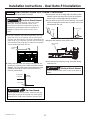
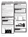
STEP 6
CONNECTING WATER
SUPPLY
Ŷ Locate and bring the tubing to the front of the
cabinet.
Ŷ Turn the water on to flush debris from the line. Run
about a quart of water through the tubing into a
bucket, then shut off the water.
Ŷ Remove strain relief screw to allow for enough slack
to make a proper water connection. (Screw must be
replaced in the next step.)
Copper Tubing:
Ŷ Slip a 1/4” nut and ferrule (provided) over both ends
of the copper tubing. Insert the tube into the union
fitting on the unit and tighten the nut to the union.
Ŷ Turn on the water to check for leaks.
SmartConnect
™
Tubing:
NOTE: The only GE Appliances-approved plastic
tubing is supplied in the SmartConnect
™
Refrigerator
Tubing kits. Do not use any other plastic water supply
line because the line is under pressure at all times.
Other types of plastic may crack or rupture with age
and cause water damage to your home.
Ŷ Insert the molded end of the tubing into the
refrigerator or freezer connection. Tighten the
compression nut until it is just hand-tight.
Ŷ Follow the instructions provided with the tubing.
Overtightening can cause leaks!
Ŷ Turn on the water to check for leaks.
Freezer
Water Supply
House
Water Supply
Refrigerator/
Freezer
Water Supply
Strain Relief
Screw
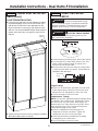
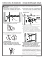
STEP 7 INSERTING/SECURING
INTO CABINET SURROUND
Ŷ Plug both units into the outlet in the wall.
Ŷ Find the installation string that is attached to the door
of the unit; this is to be used as you are pushing the
unit back into the opening. The string is attached to
the power cord; as you walk the unit back into the
opening you should pull the string tight to make sure
the power cord is routed underneath the unit.
Ŷ Slowly walk both units into opening making sure not
to touch the cabinetry on the sides and top to prevent
damage. Both door faces should be 7/8” behind
the front face of surrounding cabinets on either a
stainless or custom panel installation.
Ŷ Place power cord on its edge and pull under product
between rollers and away from the anti-tip bracket to
ensure cord is not damaged during installation.
Ŷ As you walk the unit back into the opening, you
should pull the string tight to make sure the power
cord is routed underneath the unit.
WARNING
Tip Over Hazard.
These appliances are top heavy, especially with
any doors open, and must be secured to prevent
tipping forward which could result in death or
serious injury.
WARNING
Electrical Shock Hazard.
To reduce the risk of electrical shock, be careful
during the remaining installation steps not to touch
wiring or electrical components inside the compressor
compartment while the appliance is plugged in and
the front access cover is not in place.
Installation
String
Power Cord
String
WARNING
Connect to potable water supply
only. A cold water supply is required for automatic
icemaker operation. The water pressure must be
between 40 and 120 psi (275-827 kilopascals).
WARNING
ELECTRIC SHOCK HAZARD
Attach tubing clamp using existing hole only. DO
NOT drill into the refrigerator.

20
31-1000190 Rev. 4
STEP 7 INSERTING/SECURING
INTO CABINET SURROUND (Cont.)
Ŷ Replace the waterline strain relief screw.
Ŷ Store the excess string, and water tubing under
the unit.
Installation Instructions - Dual Integrated Installation
WARNING
Electrical Shock Hazard.
Replace waterline strain relief in front rail location as
shown.
Strain Relief
Screw
STEP 8 LEVEL UNIT
All models have 4-point leveling. The front is supported
by leveling legs; the rear is supported by adjustable
wheels. Both are accessible from the front of the unit.
Ŷ To level the back of the unit, turn the 7/16” hex nut
located above the front wheels. Turn clockwise to
raise or counterclockwise to lower the unit.
Ŷ For front leveling, use a 7/16” open-end wrench.
Ŷ Adjust height of unit to match installation cutout
opening 84”. The unit should be level and plumb with
cabinetry.
NOTICE: The rear leveling wheels and front leveling
legs are limited to a maximum height adjustment of 1”.
If the installation requires more than 84” height, the
installer should elevate the unit on a sheet of plywood
or runners. Cabinetry trim could also be added across
the top of the opening to shorten the opening. If you
attempt to raise the unit more than 1”, you will damage
the front leveling legs and the rear leveling wheels.
Hex nut adjusts
rear wheels
Open-end wrench
adjusts front
leveling legs
La page est en cours de chargement...
La page est en cours de chargement...
La page est en cours de chargement...
La page est en cours de chargement...
La page est en cours de chargement...
La page est en cours de chargement...
La page est en cours de chargement...
La page est en cours de chargement...
La page est en cours de chargement...
La page est en cours de chargement...
La page est en cours de chargement...
La page est en cours de chargement...
La page est en cours de chargement...
La page est en cours de chargement...
La page est en cours de chargement...
La page est en cours de chargement...
La page est en cours de chargement...
La page est en cours de chargement...
La page est en cours de chargement...
La page est en cours de chargement...
La page est en cours de chargement...
La page est en cours de chargement...
La page est en cours de chargement...
La page est en cours de chargement...
La page est en cours de chargement...
La page est en cours de chargement...
La page est en cours de chargement...
La page est en cours de chargement...
La page est en cours de chargement...
La page est en cours de chargement...
La page est en cours de chargement...
La page est en cours de chargement...
La page est en cours de chargement...
La page est en cours de chargement...
La page est en cours de chargement...
La page est en cours de chargement...
La page est en cours de chargement...
La page est en cours de chargement...
La page est en cours de chargement...
La page est en cours de chargement...
La page est en cours de chargement...
La page est en cours de chargement...
La page est en cours de chargement...
La page est en cours de chargement...
La page est en cours de chargement...
La page est en cours de chargement...
La page est en cours de chargement...
La page est en cours de chargement...
La page est en cours de chargement...
La page est en cours de chargement...
La page est en cours de chargement...
La page est en cours de chargement...
La page est en cours de chargement...
La page est en cours de chargement...
La page est en cours de chargement...
La page est en cours de chargement...
La page est en cours de chargement...
La page est en cours de chargement...
La page est en cours de chargement...
La page est en cours de chargement...
La page est en cours de chargement...
La page est en cours de chargement...
La page est en cours de chargement...
La page est en cours de chargement...
La page est en cours de chargement...
La page est en cours de chargement...
La page est en cours de chargement...
La page est en cours de chargement...
La page est en cours de chargement...
La page est en cours de chargement...
La page est en cours de chargement...
La page est en cours de chargement...
La page est en cours de chargement...
La page est en cours de chargement...
La page est en cours de chargement...
La page est en cours de chargement...
La page est en cours de chargement...
La page est en cours de chargement...
La page est en cours de chargement...
La page est en cours de chargement...
La page est en cours de chargement...
La page est en cours de chargement...
La page est en cours de chargement...
La page est en cours de chargement...
La page est en cours de chargement...
La page est en cours de chargement...
La page est en cours de chargement...
La page est en cours de chargement...
La page est en cours de chargement...
La page est en cours de chargement...
La page est en cours de chargement...
La page est en cours de chargement...
La page est en cours de chargement...
La page est en cours de chargement...
La page est en cours de chargement...
La page est en cours de chargement...
La page est en cours de chargement...
La page est en cours de chargement...
La page est en cours de chargement...
La page est en cours de chargement...
La page est en cours de chargement...
La page est en cours de chargement...
La page est en cours de chargement...
La page est en cours de chargement...
La page est en cours de chargement...
La page est en cours de chargement...
La page est en cours de chargement...
La page est en cours de chargement...
La page est en cours de chargement...
La page est en cours de chargement...
La page est en cours de chargement...
La page est en cours de chargement...
La page est en cours de chargement...
La page est en cours de chargement...
La page est en cours de chargement...
La page est en cours de chargement...
La page est en cours de chargement...
La page est en cours de chargement...
La page est en cours de chargement...
La page est en cours de chargement...
La page est en cours de chargement...
La page est en cours de chargement...
La page est en cours de chargement...
La page est en cours de chargement...
La page est en cours de chargement...
La page est en cours de chargement...
La page est en cours de chargement...
La page est en cours de chargement...
La page est en cours de chargement...
La page est en cours de chargement...
La page est en cours de chargement...
La page est en cours de chargement...
La page est en cours de chargement...
La page est en cours de chargement...
La page est en cours de chargement...
La page est en cours de chargement...
La page est en cours de chargement...
La page est en cours de chargement...
La page est en cours de chargement...
La page est en cours de chargement...
La page est en cours de chargement...
La page est en cours de chargement...
La page est en cours de chargement...
La page est en cours de chargement...
La page est en cours de chargement...
La page est en cours de chargement...
La page est en cours de chargement...
La page est en cours de chargement...
La page est en cours de chargement...
La page est en cours de chargement...
La page est en cours de chargement...
La page est en cours de chargement...
La page est en cours de chargement...
La page est en cours de chargement...
La page est en cours de chargement...
La page est en cours de chargement...
-
 1
1
-
 2
2
-
 3
3
-
 4
4
-
 5
5
-
 6
6
-
 7
7
-
 8
8
-
 9
9
-
 10
10
-
 11
11
-
 12
12
-
 13
13
-
 14
14
-
 15
15
-
 16
16
-
 17
17
-
 18
18
-
 19
19
-
 20
20
-
 21
21
-
 22
22
-
 23
23
-
 24
24
-
 25
25
-
 26
26
-
 27
27
-
 28
28
-
 29
29
-
 30
30
-
 31
31
-
 32
32
-
 33
33
-
 34
34
-
 35
35
-
 36
36
-
 37
37
-
 38
38
-
 39
39
-
 40
40
-
 41
41
-
 42
42
-
 43
43
-
 44
44
-
 45
45
-
 46
46
-
 47
47
-
 48
48
-
 49
49
-
 50
50
-
 51
51
-
 52
52
-
 53
53
-
 54
54
-
 55
55
-
 56
56
-
 57
57
-
 58
58
-
 59
59
-
 60
60
-
 61
61
-
 62
62
-
 63
63
-
 64
64
-
 65
65
-
 66
66
-
 67
67
-
 68
68
-
 69
69
-
 70
70
-
 71
71
-
 72
72
-
 73
73
-
 74
74
-
 75
75
-
 76
76
-
 77
77
-
 78
78
-
 79
79
-
 80
80
-
 81
81
-
 82
82
-
 83
83
-
 84
84
-
 85
85
-
 86
86
-
 87
87
-
 88
88
-
 89
89
-
 90
90
-
 91
91
-
 92
92
-
 93
93
-
 94
94
-
 95
95
-
 96
96
-
 97
97
-
 98
98
-
 99
99
-
 100
100
-
 101
101
-
 102
102
-
 103
103
-
 104
104
-
 105
105
-
 106
106
-
 107
107
-
 108
108
-
 109
109
-
 110
110
-
 111
111
-
 112
112
-
 113
113
-
 114
114
-
 115
115
-
 116
116
-
 117
117
-
 118
118
-
 119
119
-
 120
120
-
 121
121
-
 122
122
-
 123
123
-
 124
124
-
 125
125
-
 126
126
-
 127
127
-
 128
128
-
 129
129
-
 130
130
-
 131
131
-
 132
132
-
 133
133
-
 134
134
-
 135
135
-
 136
136
-
 137
137
-
 138
138
-
 139
139
-
 140
140
-
 141
141
-
 142
142
-
 143
143
-
 144
144
-
 145
145
-
 146
146
-
 147
147
-
 148
148
-
 149
149
-
 150
150
-
 151
151
-
 152
152
-
 153
153
-
 154
154
-
 155
155
-
 156
156
-
 157
157
-
 158
158
-
 159
159
-
 160
160
-
 161
161
-
 162
162
-
 163
163
-
 164
164
-
 165
165
-
 166
166
-
 167
167
-
 168
168
-
 169
169
-
 170
170
-
 171
171
-
 172
172
-
 173
173
-
 174
174
-
 175
175
-
 176
176


GE ZIF301NPNII Guide d'installation
- Catégorie
- Frigos
- Taper
- Guide d'installation
- Ce manuel convient également à
dans d''autres langues
- English: GE ZIF301NPNII Installation guide
- español: GE ZIF301NPNII Guía de instalación
Documents connexes
Autres documents
-
Monogram ZIF301NPNII Guide d'installation
-
Monogram ZIR301NBRII Guide d'installation
-
Signature Kitchen Suite SKSFD3604P Guide d'installation
-
Monogram ZKR36R Manuel utilisateur
-
-
Monogram ZKMV Manuel utilisateur
-
-
KitchenAid KBBX104EPA Guide d'installation
-
 Yardistry YP21015 Mode d'emploi
-
Ryobi A99HPR1 Le manuel du propriétaire
