Kichler Lighting 49297BKTLED Manuel utilisateur
- Taper
- Manuel utilisateur

Date Issued: 09/27/17
IS-49297LED-CB
We’re here to help 866-558-5706
Hrs: M-F 9am to 5pm EST
CAUTION – RISK OF SHOCK –
Disconnect Power at the main circuit breaker panel or main
fusebox before starting and during the installation.
5) Make wire connections. Reference chart below for correct con-
nections and wire accordingly.
6) Carefully push wire connections back into outlet box making
sure all connections remain secure.
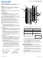
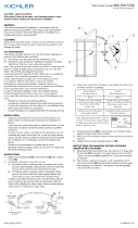
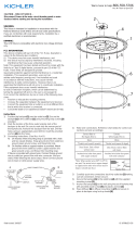
7) Secure the backpan[1] to the outlet box[2] with the supplied
mounting screws[3]. Make sure wires do not get pinched.
8) Anchor the backpan[1] to the wall using the set of holes at
each end of xture using the provided wood screws[5] and
plastic anchors[4].
9) Slide end caps[7] over glass[8] and secure in place to backpan
using lock-up knobs[9].
INSTRUCTIONS FOR MOUNTING FIXTURE OUTDOORS
AND/OR IN WET LOCATIONS.
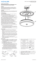
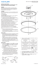
10) Mounting surface should be clean, dry, at and 1/4” larger that
the backpan[1] on all sides. Any gaps between the mounting
surface and backpan[1] exceeding 3/16” should be corrected
as required.
11) With silicone caulking compound, caulk completely around
where the backpan[1] meets the wall surface to prevent water
from seeping into outlet box. The bottom of the backpan[1]
should be left un-caulked.
12) Place the glass[6] over the backpan[1] and secure with the
screws provided.
13) With silicone caulk, caulk the top only of the glass[6] where it
meets the wall surface. The sides and bottom need no caulk-
ing.
WARNING:
This xture is intended for installation in accordance with the
National Electrical Code (NEC) and all local code specications.
If you are not familiar with code requirements, installation by a
certied electrician is recommended.
CLEANING:
Always be certain that electric current is turned off before cleaning.
Only a damp cloth should be used. Harsh cleaning products may
damage the nish.
FCC INFORMATION:
This device complies with part 15 of the FCC Rules. Operation is
subject to the following two conditions:
(1) This device may not cause harmful interference, and
(2) this device must accept any interference received, including
interference that may cause undesired operation.
Note: This equipment has been tested and found to comply with the
limits for a Class B digital device, pursuant to part 15 of the FCC
Rules. These limits are designed to provide
reasonable protection against harmful interference in a residential
installation. This equipment generates, uses and can
radiate radio frequency energy and, if not installed and used
in accordance with the instructions, may cause harmful
interference to radio communications. However, there is no
guarantee that interference will not occur in a particular installation.
If this equipment does cause harmful interference
to radio or television reception, which can be determined by
turning the equipment off and on, the user is encouraged to
try to correct the interference by one or more of the following mea-
sures:
• Reorient or relocate the receiving antenna.
• Increase the separation between the equipment and receiver.
• Connect the equipment into an outlet on a circuit different from
that to which the receiver is connected.
• Consult the dealer or an experienced radio/TV technician for help.
INSTALLATION:
• Read and understand all instructions and illustrations complete-
ly before proceeding with assembly and installation of xture.
• If you have any doubts about how to install this xture, or if the
xture fails to operate completely, please contact a qualied
electrician.
• All parts must be used as indicated in the instructions. Do not sub-
stitute any parts, leave parts out, or use any parts that are worn
or broken. Failure to obey this instruction could invalidate the UL
listing, C.S.A. certication, and/or ETL listing of this xture.
• Fixture is to be connected to a single branch circuit.
• Mounting surface should be clean, dry, at and 1/4” larger than
the xture housing surface.
INSTRUCTIONS:
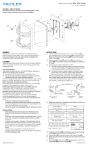
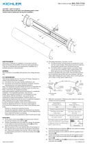
1) At the center of the backpan[1] are knockout slots. Remove the
set that matches your outlet box[2].
2) Position the backpan over the outlet box. Secure the backpan
to the outlet box using mounting strap screws[3] provided.
3) Mark the location of the outer keyhole slots of the backpan to
the wall. Remove the backpan from the wall. Drill the holes
using an appropriately sized drill bit. Insert the provided an-
chors[4] into the holes.
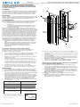
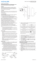
4) Grounding instructions: (See Illus. A or B).
A) On xtures where mounting strap is provided with a hole
and two raised dimples. Wrap ground wire from outlet box
around green ground screw, and thread into hole.
B) On xtures where a cupped washer is provided. Attach
ground wire from outlet box under cupped washer and
green ground screw, and thread into mounting strap.
If xture is provided with ground wire. Connect xture ground
wire to outlet box ground wire with wire connector. (Not pro-
vided.) After following the above steps. Never connect ground
wire to black or white power supply wires.
GREEN GROUND
SCREW
CUPPED
WASHER
OUTLET BOX
GROUND
FIXTURE
GROUND
DIMPLES
WIRE CONNECTOR
OUTLET BOX
GROUND
GREEN GROUND
SCREW
FIXTURE
GROUND
A
B
Connect Black or
Red Supply Wire to:
Connect
White Supply Wire to:
Black White
*Parallel cord (round & smooth) *Parallel cord (square & ridged)
Clear, Brown, Gold or Black
without tracer
Clear, Brown, Gold or Black
with tracer
Insulated wire (other than green)
with copper conductor
Insulated wire (other than green)
with silver conductor
*Note: When parallel wires (SPT I & SPT II)
are used. The neutral wire is square shaped
or ridged and the other wire will be round in
shape or smooth (see illus.)
Neutral Wire
2
7
3
5
1
6
4

Date Issued: 09/27/17
IS-49297LED-CB
INSTRUCTIONS
For Assembling and Installing Fixtures in Canada
Pour L’assemblage et L’installation Au Canada
Nous sommes là pour vous aider 866-558-5706
Heures : du lundi au vendredi, de 9h à 17h (heure de l’Est)
ATTENTION – RISQUE DE DÉCHARGES ÉLECTRIQUES -
Couper le courant au niveau du panneau du disjoncteur du
circuit principal ou de la boîte à fusibles principale avant de
procéder à l’installation.
ATTENTION:
Ce luminaire doit être installé conformément aux codes d’électricité
nationaux (NEC) et satisfaire toutes les spécications des codes
locaux. Si vous ne connaissez pas les exigences de ces codes, il
est recommandé de coner l’installation à un électricien certié.
NETTOYAGE:
Toujours veiller à ce que le courant électrique soit coupé avant de
nettoyer. Utiliser uniquement un chiffon doux humidié. Les produits
de nettoyage trop puissants peuvent endommager la nition.
FCC INFORMATION:
Cet appareil est conforme à la section 15 de la réglementation de la
FCC. L’exploitation est soumise aux deux conditions suivantes :
(1) Cet équipement ne doit pas causer d’interférences
nuisibles, et
(2) cet équipement doit accepter toute interférence reçue, y
compris les interférences risquant d’engendrer un fonc-
tionnement indésirable.
Remarque: Des tests ont conrmé que ce matériel respecte les
limites d’un dispositif numérique de catégorie B, en vertu de la sec-
tion 15 de la réglementation de la FCC. Ces limites ont été conçues
pour fournir une protection raisonnable contre le brouillage nuisible
d’une installation résidentielle. Cet équipement génère, utilise et
peut rayonner de l’énergie radiofréquence et, s’il n’est pas installé
et utilisé selon les instructions, peut causer de l’interférence nuis-
ible aux communications de radio. Cependant, il est néanmoins
possible qu’il y ait de l’interférence dans une installation en particu-
lier. Si cet équipement cause du brouillage nuisible à la réception
du signal de radio ou de télévision, ce qui peut être déterminé en
éteignant puis en rallumant l’appareil, l’usager peut essayer de cor-
riger l’interférence en appliquant une des mesures suivantes :
• Réorienter l’antenne de réception ou changer son emplace-
ment.
• Augmenter la distance séparant l’équipement et le récepteur.
• Brancher le matériel dans la prise de courant d’un circuit dif-
férent de celui auquel le récepteur est branché.
• Consulter le revendeur ou un technicien radio/télé
d’expérience.
ATTENTION - RISQUE DE CHOCS ÉLECTRIQUES -
Déconnecter l’alimentation au niveau du boîtier du panneau
principal à fusibles ou à disjoncteurs avant de procéder à
l’installation et pendant l’installation.
• Lire et comprendre toutes les instructions et illustrations avant
de procéder au montage et à l’installation du luminaire.
• En cas de doute sur l’installation de ce luminaire, ou si le
luminaire ne fonctionne pas correctement, prière de contacter
un électricien agréé.
• Utiliser toutes les pièces selon les instructions. Ne pas
substituer de pièces, exclure certaines pièces du montage ou
se servir de pièces usées ou endommagées. Le non-respect
de ces instructions risque d’annuler l’homologation UL, le
certificat C.S.A. ainsi que l’homologation ETL de ce luminaire.
• Le luminaire doit être connecté à un circuit dédié.
• La surface de montage doit être propre, sèche, plate et plus
grande de 0,6 cm que la surface du boîtier du luminaire.
INSTRUCTIONS:
1) Au centre de l’arrière-cour [1] sont des machines à sous. Re-
tirez l’ensemble qui correspond à votre boîte de sortie [2].
2) Placez l’arrière-plan sur la boîte de sortie. Fixez l’arrière-plan à
la boîte de sortie en utilisant les vis de sangle de montage [3]
fournies (ce sont les plus courtes des deux vis).
3) Marquez l’emplacement des fentes de trou de serrure extéri-
eures de l’arrière-plan sur le mur. Assurez-vous de ne marquer
que la partie étroite de la fente de la serrure. Retirez l’arrière-
plan du mur. Percez les trous en utilisant un foret de taille
appropriée. Insérer les ancres fournies [4] dans les trous.
4) Connecter les ls. Se porter au tableau ci-dessous pour faire
les connexions.
5) Appuyer avec précaution sur les connexions de l [4] dans la
boîte de sortie en s’assurant que toutes les connexions restent
sécurisées.
6) Fixez le contre-appui sur la boîte de sortie avec les vis de xa-
tion fournies [3].
7) Fixez l’arrière-plan sur le mur en utilisant l’ensemble des trous
à chaque extrémité de l’appareil à l’aide des vis à bois fournies
[5] et des ancrages en plastique [6].
8) Glisser les embouts [7] sur le verre [8] et le xer en place à
l’arrière en utilisant les boutons de verrouillage [9].
INSTRUCTIONS DE MONTAGE DE LUMINAIRE À L’EXTÉRIEUR
ET/OU DANS DES LIEUX HUMIDES. .
10) La surface de montage doit être propre, sec, plat et 0,6 cm
plus épais que l’arrière [1] sur tous les côtés. Tout jeu entre la
surface de montage et l’arrière-plan [1] dépassant 0,5 cm doit
être rectié au besoin.
11) À l’aide de scellants de silicone, calfeutrez bien où l’arrière de
l’arrière-plan [1] entre en contact avec le mur pour empêcher
l’eau d’entrer dans la boîte de jonction. Le fond de l’arrière-plan
[1] doit être laissé sans calfeutrage.
12) Placez le verre [6] sur l’arrière [1] et xez-le avec les vis
fournies.
13) Avec calfeutrage en silicone, calfeutrez le dessus du verre
[6] où il rencontre la surface du mur. Les côtés et le fond ne
nécessitent aucun calfeutrage.
Connecter le fil noir ou
rouge de la boite
Connecter le fil blanc de la boîte
A Noir A Blanc
*Au cordon parallèle (rond et lisse)
*Au cordon parallele (à angles droits el strié)
Au bransparent, doré, marron, ou
noir sans fil distinctif
Au transparent, doré, marron, ou
noir avec un til distinctif
Fil isolé (sauf fil vert) avec
conducteur en cuivre
Fil isolé (sauf fil vert) avec
conducteur en argent
*Remarque: Avec emploi d’un fil paralléle
(SPT I et SPT II). Le fil neutre est á angles
droits ou strié et l’autre fil doit étre rond ou
lisse (Voir le schéma).
Fil Neutre
2
7
3
5
1
6
4
-
 1
1
-
 2
2


Kichler Lighting 49297BKTLED Manuel utilisateur
- Taper
- Manuel utilisateur
dans d''autres langues
Documents connexes
-
 Kichler Lighting 11302CPLED Manuel utilisateur
-
 Kichler Lighting 11303CPLED Manuel utilisateur
-
 Kichler Lighting 11320BKTLED Manuel utilisateur
-
 Kichler Lighting 49898BKLED Manuel utilisateur
-
 Kichler Lighting 49945BKTLED Manuel utilisateur
-
 Kichler Lighting 49946BKTLED Manuel utilisateur
-
Kichler Lighting 5367CH Manuel utilisateur
-
 Kichler Lighting 10769NILED Manuel utilisateur
-
 Kichler Lighting 11304NILED Manuel utilisateur
-
 Kichler Lighting 10788NILED Manuel utilisateur


