Faber WIREBOX2 Wiring Box Kit Manuel utilisateur
- Taper
- Manuel utilisateur

WIREBOX2
Installation Instructions
Instructions d'installation
Instrucciones de instalación
WIRING BOX KIT
KIT BOÎTE DE CÂBLAGE
KIT DE LA CAJA DE CABLEADO

2
READ AND SAVE THESE INSTRUCTIONS BEFORE
YOU START INSTALLING THIS RANGEHOOD
WARNING: TO REDUCE THE RISK OF FIRE, ELECTRIC SHOCK, OR INJURY TO
PERSONS, OBSERVE THE FOLLOWING:
a) Installationworkandelectricalwiringmustbedonebyqualiedperson(s)inac-
cordancewithallapplicablecodesandstandards,includingre-ratedconstruction.
b) When cutting or drilling into wall or ceiling, do not damage electrical wiring and
otherhiddenutilities.
CAUTION: To reduce The Risk Of Fire and Electric Shock, this Rangehood Wiring
Box Kit shall be used only with Faber Rangehood Models that have been investi-
gatedandfoundacceptableforusewiththisKit.Seehoodmanualtodetermine
compatibility.

3
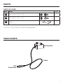
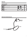
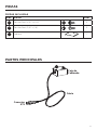
PARTS
REF. PART QTY
HPozi Screws (2/16" x 6/16") 2
GPozi Screws (3/16" x 1/8") 2
ICover 1
PARTS INCLUDED
Wiring Box
STS
Connector
Cable
MAIN PARTS
I
NOTE: this is only used with the Breva hood products.

4
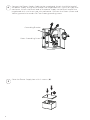
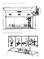
1
2
Disconnect the power cable from the control box.
Remove the power cable from the hood and away from the strain relief.
Place the strain relief back into the hole.

5
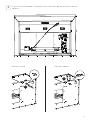
G
G
3Attach the Wiring Box to the hood with 2 screws (G) in rear or top position.
Rear position: Top position:

6
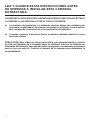
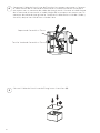
H
4
5
Connect the Power Supply Cable to the rangehood. Attach the White lead of
the power supply to the White lead of the rangehood with a twist-on type wire
connector. Attach the Black lead of the power supply to the Black lead of the
rangehood with a twist-on type wire connector. Connect the Green (Green and
Yellow) ground wire under the Free Green grounding screw.
Close the Power Supply box with 2 screws (H).
Grounding Bracket
Green Grounding Screw
Grounding Bracket
Green Grounding Screw

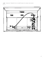
7
6Connect the Power Supply Cable to the rangehood.

8
LISEZ ET CONSERVEZ CES INSTRUCTIONS AVANT
DE COMMENCER L'INSTALLATION DE CETTE HOTTE
AVERTISSEMENT:POURRÉDUIRELESRISQUESD'INCENDIE,DECHOC
ÉLECTRIQUEOUDEBLESSURE,RESPECTEZLESCONSIGNESSUIVANTES:
a) Conezlestravauxd'installationetlecâblageélectriqueàuneouplusieurs
personnesqualiées,conformémentàtouslescodesetnormesapplicables,
ycomprislesconstructionsrésistantesaufeu.
b) Lorsquevouscoupezoupercezunmurouunplafond,n'endommagezpasle
câblageélectriqueetlesautreséquipementscachés.
ATTENTION:Pourréduirelesrisquesd'incendieetdechocsélectriques,cekitde
boîtedecâblagedehottenedoitêtreutiliséqu'aveclesmodèlesdehotteFaber
quiontétéexaminésetjugésacceptablespourl'utilisationdecekit.Voirlemanuel
delahottepourdéterminerlacompatibilité.

9
PIÈCES
RÉF. PIÈCE QTÉ
HVis Pozi (2/16" x 6/16") 2
GVis Pozi (3/16" x 1/8") 2
ICouvercle 1
PIÈCES INCLUSES
I
Boîte de
câblage
Connecteur
STS
Câble
PIÈCES PRINCIPALES

10
1
2
Débranchez le câble d'alimentation de la boîte ATF.
Retirez le câble d'alimentation de la hotte.
Fermez la fente du câble d'alimentation.

11
G
G
3Fixez le boîtier de câblage à la hotte à l'aide de 2 vis (G) en position arrière ou
supérieure.
Position arrière: Position supérieure:

12
Grounding Bracket
Green Grounding Screw
H
4
5
Connectez le câble d'alimentation à la hotte. Fixez le fil blanc de l'alimentation
au fil blanc de la hotte avec un connecteur de type torsadé. Fixez le fil noir de
l'alimentation au fil noir de la hotte à l'aide d'un connecteur de type torsadé.
Connectez le fil de terre vert (vert et jaune) sous la vis de mise à la terre verte
libre.
Fermez le câble d'alimentation avec 2 vis (H).
Support de mise à la terre
Vis de mise à la terre verte

13
6Connectez le câble d'alimentation à la hotte.

14
LEA Y GUARDE ESTAS INSTRUCCIONES ANTES
DE EMPEZAR A INSTALAR ESTA CAMPANA
EXTRACTORA
ADVERTENCIA:PARAREDUCIRELRIESGODEINCENDIO,DESCARGAELÉCTRICA
O LESIONES A LAS PERSONAS, CUMPLA CON LO SIGUIENTE:
a) Lostrabajosdeinstalaciónyelcableadoeléctricodebenserrealizadospor
persona(s)cualicada(s)deacuerdocontodosloscódigosynormasaplica-
bles,incluyendolaconstrucciónconclasicacióndeincendios.
b) Alcortaroperforarlaparedoeltecho,nodañeelcableadoeléctriconiotros
serviciosocultos.
PRECAUCIÓN:Parareducirelriesgodeincendioydedescargaeléctrica,estekit
deCajadeCableadodelaCampanadebeserutilizadosoloconlosModelosde
CampanasExtractorasFaberquehansidoinvestigadosyencontradosaceptables
parasuusoconestekit.Consulteelmanualdelacampanaparadeterminarla
compatibilidad.

15
PIEZAS
REF. PIEZA CANT
HTornillos Pozi (2/16" x 6/16") 2
GTornillos Pozi (3/16" x 1/8") 2
ICubierta 1
PIEZAS INCLUIDAS
I
Caja de
Cableado
Conector
STS
Cable
PARTES PRINCIPALES

16
1
2
Desconecte el cable de alimentación de la caja ATF.
Retire el Cable de Alimentación de la campana.
Cierre la ranura del Cable de Alimentación.

17
G
G
3Fije la Caja de Cableado a la campana con 2 tornillos (G) en posición trasera o
superior.
Posición trasera: Posición superior:

18
H
4
5
Grounding Bracket
Green Grounding Screw
Conecte el Cable de Suministro de Energía a la campana extractora. Conecte
el cable Blanco de la fuente de alimentación al cable Blanco de la campana
extractora con un conector de cable de tipo giratorio. Conecte el cable Negro
de la fuente de alimentación al cable Negro de la campana extractora con un
conector de cable de tipo giratorio. Conecte el cable de tierra Verde (Verde y
Amarillo) bajo el tornillo de tierra Verde Libre.
Cierre el Cable de Suministro de Energía con 2 tornillos (H).
Soporte de Conexión a Tierra
Tornillo Verde de Conexión a Tierra

19
6Conecte el Cable de Suministro de Energía a la campana extractora.

991.0682.101_01 - 220524
D000000008736_00
-
 1
1
-
 2
2
-
 3
3
-
 4
4
-
 5
5
-
 6
6
-
 7
7
-
 8
8
-
 9
9
-
 10
10
-
 11
11
-
 12
12
-
 13
13
-
 14
14
-
 15
15
-
 16
16
-
 17
17
-
 18
18
-
 19
19
-
 20
20


Faber WIREBOX2 Wiring Box Kit Manuel utilisateur
- Taper
- Manuel utilisateur
dans d''autres langues
Documents connexes
-
Faber Inca Smart 28 Stainless Steel 240 Le manuel du propriétaire
-
-
Faber Stratus 48 SS Guide d'installation
-
-
-
-
-
-
-