Faber DAMA30SSV2 30 Inch Pyramid Wall Hood Manuel utilisateur
- Catégorie
- Hottes
- Taper
- Manuel utilisateur

DAMA30SSV2
DAMA36SSV2
Installation Instructions
Use and Care Information
Instructions d'installation
Utilisez et d'entretien
Instrucciones de instalación
Información de uso y cuidado
DAMA

2
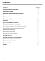
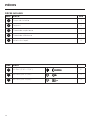
CONTENTS
Section Page
Important safety instructions
3
Range hood dimensions
6
Installation height requirements
7
Parts
8
Tools needed
10
Venting method
11
Installing
12
Choosing venting method
17
Attach venting: ducted
18
Attach venting: non ducted recirculating
22
Connecting house power
26
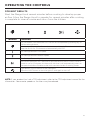
Operating the controls
27
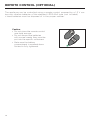
Remote Control (Optional)
28
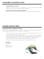
Cleaning stainless steel
29
Caring for lters
29
Cleaning metal grease lters
29
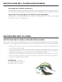
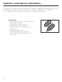
Replacing the activated charcoal lter
30
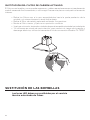
Replacing bulbs
30
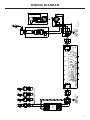
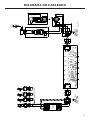
Wiring diagram
31
Warranty
32

3
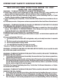
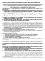
IMPORTANT SAFETY INSTRUCTIONS
READ AND SAVE THESE INSTRUCTIONS BEFORE YOU START
INSTALLING THIS RANGEHOOD
WARNING: - TO REDUCE THE RISK OF A RANGE TOP GREASE FIRE:
a) Never leave surface units unattended at high settings. Boilovers cause smoking and
greasy spillovers that may ignite. Heat oils slowly on low or medium setting.
b) Always turn hood ON when cooking at high heat or when ambeing food (i.e. Crepes
Suzette, Cherries Jubilee, Peppercorn Beef Flambé).
c) Clean ventilating fans frequently. Grease should not be allowed to accumulate on fan or
lter.
d) Use proper pan size. Always use cookware appropriate for the size of the surface element.
WARNING: - TO REDUCE THE RISK OF INJURY TO PERSONS IN THE EVENT OF A RANGE
TOP GREASE FIRE, OBSERVE THE FOLLOWING*:
a) SMOTHER FLAMES with a close-tting lid, cookie sheet, or metal tray, then turn off the
burner. BE CAREFUL TO PREVENT BURNS. If the ames do not go out immediately
EVACUATE AND CALL THE FIRE DEPARTMENT.
b) NEVER PICK UP A FLAMING PAN - You may be burned.
c) DO NOT USE WATER, including wet dishcloths or towels - a violent steam explosion will
result.
d) Use an extinguisher ONLY if:
1. You know you have a Class ABC extinguisher, and you already know how to operate
it.
2. The re is small and contained in the area where it started.
3. The re department is being called.
4. You can ght the re with your back to an exit.
* Based on "Kitchen Firesafety Tips" published by NFPA
WARNING - TO REDUCE THE RISK OF FIRE OR ELECTRIC SHOCK, do not use this fan with
any solid-state speed control device.
WARNING - TO REDUCE THE RISK OF FIRE, ELECTRICAL SHOCK, OR INJURY TO PERSONS,
OBSERVE THE FOLLOWING:
1. Use this unit only in the manner intended by the manufacturer. If you have any questions,
contact the manufacturer.
2. Before servicing or cleaning unit, switch power off at service panel and lock the service
disconnecting means to prevent power from being switched on accidentally. When the
service disconnecting means cannot be locked, securely fasten a prominent warning
device, such as a tag, to the service panel.
CAUTION: For General Ventilating Use Only. Do Not Use To Exhaust Hazardous or Explo-
sive Materials and Vapors.
WARNING - TO REDUCE THE RISK OF FIRE, ELECTRICAL SHOCK, OR INJURY TO PERSONS,
OBSERVE THE FOLLOWING:
1. Installation Work And Electrical Wiring Must Be Done By Qualied Person(s) In Accor-
dance With All Applicable Codes And Standards, Including Fire-Rated Construction.
2. Sufcient air is needed for proper combustion and exhausting of gases through the
ue (chimney) of fuel burning equipment to prevent backdrafting. Follow the heating

4
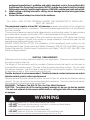
• Venting system MUST terminate outside the home.
• DO NOT terminate the ductwork in an attic or other enclosed space.
• DO NOT use 4" laundry-type wall caps.
• Flexible-type ductwork is not recommended.
• DO NOT obstruct the ow of combustion and ventilation air.
• Failure to follow venting requirements may result in a re.
WARNING
!
equipment manufacturer's guideline and safety standards such as those published by
the National Fire Protection Association (NFPA), and the American Society for Heating,
Refrigeration and Air Conditioning Engineers (ASHRAE), and the local code authorities.
3. When cutting or drilling into wall or ceiling, do not damage electrical wiring and other
hidden utilities.
4. Ducted fans must always be vented to the outdoors.
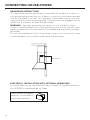
ALL WALL AND FLOOR OPENINGS WHERE THE RANGEHOOD IS INSTALLED
MUST BE SEALED.
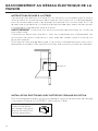
This rangehood requires at least 24" of clearance between the bottom of the rangehood
and the cooking surface or countertop. This hood has been approved by UL at this distance
from the cooktop.
This minimum clearance may be higher depending on local building codes. For gas cooktops
and combination ranges, a minimum of 30" is recommended and may be required.
Overhead cabinets on both sides of this unit must be a minimum of 18" above the cooking
surface or countertop. Consult the cooktop or range installation instructions given by the
manufacturer before making any cutouts.
MOBILE HOME INSTALLATION The installation of this rangehood must conform to the
Manufactured Home Construction and Safety Standards, Title 24 CFR, Part 3280 (formerly
Federal Standard for Mobile Home Construction and Safety, Title 24, HUD, Part 280). See
Electrical Requirements.
VENTING REQUIREMENTS
Determine which venting method is best for your application. Ductwork can extend either
through the wall or the roof.
The length of the ductwork and the number of elbows should be kept to a minimum to
provide efcient performance. The size of the ductwork should be uniform. Do not install
two elbows together. Use duct tape to seal all joints in the ductwork system. Use caulking
to seal exterior wall or oor opening around the cap.
Flexible ductwork is not recommended. Flexible ductwork creates back pressure and air
turbulence that greatly reduces performance.
Make sure there is proper clearance within the wall or oor for exhaust duct before making
cutouts. Do not cut a joist or stud unless absolutely necessary. If a joist or stud must be cut,
then a supporting frame must be constructed.
WARNING - To Reduce The Risk Of Fire, Use Only Metal Ductwork.
CAUTION - To reduce risk of re and to properly exhaust air, be sure to duct air outside
– Do not vent exhaust air into spaces within walls or ceilings or into attics, crawl spaces,
or garages.

5
ELECTRICAL REQUIREMENTS
A 120 volt, 60 Hz AC-only electrical supply is required on a separate 15 amp fused circuit.
A time-delay fuse or circuit breaker is recommended. The fuse must be sized per local
codes in accordance with the electrical rating of this unit as specied on the serial/rating
plate located inside the unit near the eld wiring compartment.
• Electrical ground is required on this rangehood.
• If cold water pipe is interrupted by plastic, nonmetallic gaskets or other materials,
DO NOT use for grounding.
• DO NOT ground to a gas pipe.
• DO NOT have a fuse in the neutral or grounding circuit. A fuse in the neutral or
grounding circuit could result in electrical shock.
• Check with a qualied electrician if you are in doubt as to whether the rangehood
is properly grounded.
• Failure to follow electrical requirements may result in a re.
WARNING
!

6
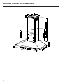
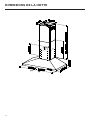
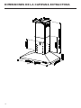
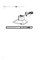
RANGE HOOD DIMENSIONS
DRAFT 27-JAN-2022 10:53
30" - 36"

7
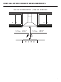
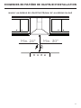
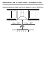
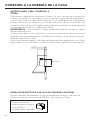
INSTALLATION HEIGHT REQUIREMENTS
MIN. 24" OVER ELECTRIC / MIN. 30" OVER GAS
Min. 24" Min. 30"

8
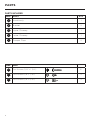
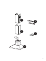
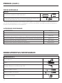
PARTS
REF. PART QTY
AHood body 1
BBracket 2
DUpper Chimney 1
ELower Chimney 1
FDamper Flaps 2
REF
PART
GPozi Screws (3/16" x 1 3/4") 6
ITorx Screws (1/8" x 7/16") 2
LTorx Screws (1/8" x 5/16") 2
PARTS INCLUDED

9
D
E
F
A
B

10
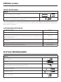
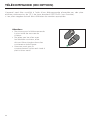
PARTS NEEDED
PARTS (cont.)
PART
6" Round Metal Ductwork
Drywall plugs or other suitable wall fasteners based on your
installation.
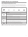
TOOLS NEEDED
TOOL
Tape Measure
Pencil
Electric Drill with 5/16" Drill Bit
Phillips Screwdriver
Torx Screwdriver
Work gloves
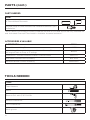
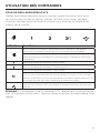
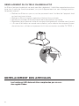
ACCESSORIES AVAILABLE
ACCESSORY SKU#
Direct Connect Wiring Box #WIREBOX
High Ceiling Chimney Kit - Upper and Lower Chimney Flue to replace
the original ue's to t up to 11' ceilings #HIGH3
Ductless Kit - Includes Ductless Diverter, Charcoal Filters #DUCT4
Activated Charcoal Filter Accessory #FILTER2
Wireless Remote Control Accessory #REMORIG
"When used in recirculation mode, to Reduce the Risk of Fire and Shock use only Ductless Kit
and Activated Charcoal Filter listed in Available Accessories below."

11
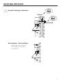
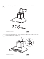
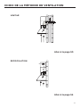
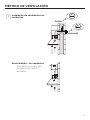
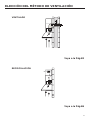
VENTING METHOD
Ducted Venting Installation
Non Ducted - Recirculation
1
Requires purchase of
Activated Charcoal
Accessory.
6"
6"
Horizontal
Vertical

12
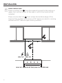
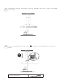
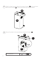
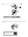
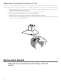
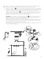
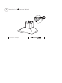
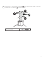
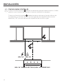
INSTALLING
DRAW CENTER LINES
Draw a vertical line X from the supporting wall to the ceiling or
upper limit, at the center of the area in which the hood will be
installed.
Draw a horizontal line Y from where the bottom edge of the
hood will be located, a minimum of 24" above an electric cooking
surface and 30" above a gas cooking surface.
2
MIN. 24" OVER ELECTRIC/MIN. 30" OVER GAS
MIN. 24" MIN. 30"
Y
X

13
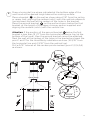
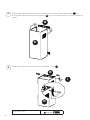
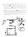
Draw a horizontal line where indicated at the bottom edge of the
vent hood at the desired height above the cooking surface.
Place a bracket B on the wall as shown about 1/8" from the ceiling
or upper limit, aligning the centers(notch) with the vertical reference
line and mark the wall at the centers of the holes in the bracket.
Place the second bracket B on the wall as shown, below the rst
bracket, at the height of the upper chimney section supplied and
aligning the centers (notch) with the vertical line.
Attention: If the position of the second bracket B below the rst
bracket is less than 19 1/2" from the horizontal reference line (at the
bottom of the hood), then the second bracket cannot be attached.
Mark the wall at the centers of the holes in the bracket and mark the
point 1 and 2 for the Hood Body installation as show (16 9/16" from
the horizontal line and 4 9/16" from the vertical line).
Drill ø 5/16" holes at all the centers points marked (point 1,2,3,4,5,6)
as shown.
3
x6
x6
´
´
´
!
´
´ ´
´
2.1
D
B

14
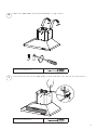
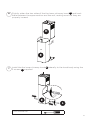
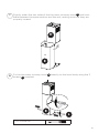
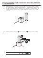
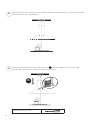
Insert not completely the two screws G supplied in the hood body fixing holes as
shown.
5
4Installation screws provided must be secured with wall plugs (purchase
separately).
I = 6x
L = 2x
OK!
3/16 “
G
Phillips Screwdriver

15
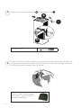
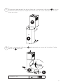
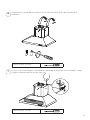
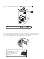
6
7
Hook the hood body onto the hood body fixing screws.
Use a level to insure that hood body is level and then fully secure the two screws.
Phillips Screwdriver
Phillips Screwdriver

16
Tighten the 2 screws G as shown.
8
G
Phillips Screwdriver

17
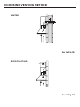
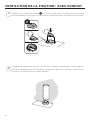
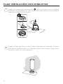
CHOOSING VENTING METHOD
VENTED
RECIRCULATING
Go to Pg.18
Go to Pg.22

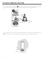
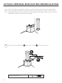
18
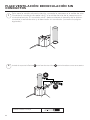
1
Install Roof or Wall Cap purchased separately. Connect the 6" metal ductwork
to the Roof or Wall Cap and then attach ductwork. Seal with foil tape.
Install the Damper aps F that are included with hood by snapping the tabs
into place inside the top of the hood before connecting ductwork.
ATTACH VENTING: DUCTED
F
2

19
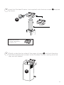
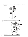
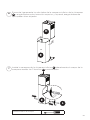
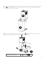
3Install the 2 Chimney brackets B to the middle and upper holes and secure
with screws G as shown.
L = 4x
G
B
B
Phillips Screwdriver

20
4
5Secure the sides to the brackets by using the 2 screws I.
Slightly widen the two sides of the upper chimney D and hook them
behind the brackets B, making sure that they are well seated.
B
D
Torx Screwdriver
N = 4x
D
I
B
La page est en cours de chargement...
La page est en cours de chargement...
La page est en cours de chargement...
La page est en cours de chargement...
La page est en cours de chargement...
La page est en cours de chargement...
La page est en cours de chargement...
La page est en cours de chargement...
La page est en cours de chargement...
La page est en cours de chargement...
La page est en cours de chargement...
La page est en cours de chargement...
La page est en cours de chargement...
La page est en cours de chargement...
La page est en cours de chargement...
La page est en cours de chargement...
La page est en cours de chargement...
La page est en cours de chargement...
La page est en cours de chargement...
La page est en cours de chargement...
La page est en cours de chargement...
La page est en cours de chargement...
La page est en cours de chargement...
La page est en cours de chargement...
La page est en cours de chargement...
La page est en cours de chargement...
La page est en cours de chargement...
La page est en cours de chargement...
La page est en cours de chargement...
La page est en cours de chargement...
La page est en cours de chargement...
La page est en cours de chargement...
La page est en cours de chargement...
La page est en cours de chargement...
La page est en cours de chargement...
La page est en cours de chargement...
La page est en cours de chargement...
La page est en cours de chargement...
La page est en cours de chargement...
La page est en cours de chargement...
La page est en cours de chargement...
La page est en cours de chargement...
La page est en cours de chargement...
La page est en cours de chargement...
La page est en cours de chargement...
La page est en cours de chargement...
La page est en cours de chargement...
La page est en cours de chargement...
La page est en cours de chargement...
La page est en cours de chargement...
La page est en cours de chargement...
La page est en cours de chargement...
La page est en cours de chargement...
La page est en cours de chargement...
La page est en cours de chargement...
La page est en cours de chargement...
La page est en cours de chargement...
La page est en cours de chargement...
La page est en cours de chargement...
La page est en cours de chargement...
La page est en cours de chargement...
La page est en cours de chargement...
La page est en cours de chargement...
La page est en cours de chargement...
La page est en cours de chargement...
La page est en cours de chargement...
La page est en cours de chargement...
La page est en cours de chargement...
La page est en cours de chargement...
La page est en cours de chargement...
La page est en cours de chargement...
La page est en cours de chargement...
La page est en cours de chargement...
La page est en cours de chargement...
La page est en cours de chargement...
La page est en cours de chargement...
La page est en cours de chargement...
La page est en cours de chargement...
La page est en cours de chargement...
La page est en cours de chargement...
-
 1
1
-
 2
2
-
 3
3
-
 4
4
-
 5
5
-
 6
6
-
 7
7
-
 8
8
-
 9
9
-
 10
10
-
 11
11
-
 12
12
-
 13
13
-
 14
14
-
 15
15
-
 16
16
-
 17
17
-
 18
18
-
 19
19
-
 20
20
-
 21
21
-
 22
22
-
 23
23
-
 24
24
-
 25
25
-
 26
26
-
 27
27
-
 28
28
-
 29
29
-
 30
30
-
 31
31
-
 32
32
-
 33
33
-
 34
34
-
 35
35
-
 36
36
-
 37
37
-
 38
38
-
 39
39
-
 40
40
-
 41
41
-
 42
42
-
 43
43
-
 44
44
-
 45
45
-
 46
46
-
 47
47
-
 48
48
-
 49
49
-
 50
50
-
 51
51
-
 52
52
-
 53
53
-
 54
54
-
 55
55
-
 56
56
-
 57
57
-
 58
58
-
 59
59
-
 60
60
-
 61
61
-
 62
62
-
 63
63
-
 64
64
-
 65
65
-
 66
66
-
 67
67
-
 68
68
-
 69
69
-
 70
70
-
 71
71
-
 72
72
-
 73
73
-
 74
74
-
 75
75
-
 76
76
-
 77
77
-
 78
78
-
 79
79
-
 80
80
-
 81
81
-
 82
82
-
 83
83
-
 84
84
-
 85
85
-
 86
86
-
 87
87
-
 88
88
-
 89
89
-
 90
90
-
 91
91
-
 92
92
-
 93
93
-
 94
94
-
 95
95
-
 96
96
-
 97
97
-
 98
98
-
 99
99
-
 100
100


Faber DAMA30SSV2 30 Inch Pyramid Wall Hood Manuel utilisateur
- Catégorie
- Hottes
- Taper
- Manuel utilisateur
dans d''autres langues
Documents connexes
-
Faber Dama 36 SSV2 with VAM Manuel utilisateur
-
-
-
-
-
-
Faber Diamante 48 SS Guide d'installation
-
-
-
Faber Classica 36 SS Guide d'installation