Yes AK7400AS Manuel utilisateur
- Catégorie
- Hottes
- Taper
- Manuel utilisateur

WWW.ZEPHYRONLINE.COM
NOV20.0101
Airflow Control Technology
TM
C
Tidal II
AK7400AS, AK7436AS, AK7448AS
EN Use, Care, and Installation Guide
FR Guide d’utilisation, d’entretien et d’installation

2
Tidal II Use, Care, and Installation Guide
TIDAL II
WALL
PRO

3
Tidal II Use, Care, and Installation Guide
ZEPHYRONLINE.COM
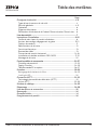
Contents
Page
Safety Information ............................................................................ 4-6
Types of Safety Warnings ................................................................... 4
General Safety ..................................................................................4-5
Operation ........................................................................................... 6
Electrical Requirements ...................................................................... 6
Federal Communication Commission Interface Statement ................. 6
List of Materials ................................................................................... 7
Installation Instructions .................................................................... 8-20
Ducting Calculation Sheet .................................................................. 8
Mounting Height, Clearance, & Ducting ...........................................9-10
Ducting Options .................................................................................11
Hood Specifications ............................................................................12
Electrical Supply .................................................................................13
Cable Lock .........................................................................................13
Horizontal Ducting Conversion ........................................................ 14-16
PBD-1300B Dual Blower Installation ..................................................17-19
Mounting the Hood ............................................................................ 20
Features & Controls ..........................................................................21-27
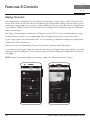
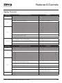
Proximity Controls ...........................................................................21-23
Zephyr Connect ..............................................................................24-25
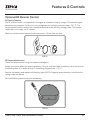
Optional RF Remote Control ............................................................26-27
Maintenance ................................................................................... 28-30
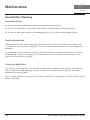
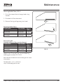
Hood & Filter Cleaning .....................................................................28-29
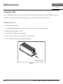
LumiLight LED ................................................................................... 30
ACT™ Conversion .............................................................................31-33
Airflow Control Technology (ACT™) ....................................................31
Enabling ACT™ ................................................................................ 32-33
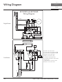
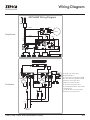
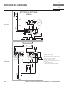
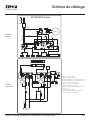
Wiring Diagram ............................................................................... 34-35
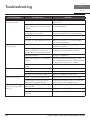
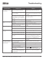
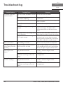
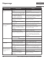
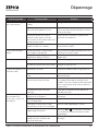
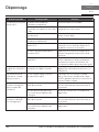
Troubleshooting............................................................................... 36-38
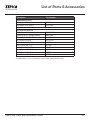
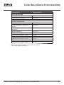
List of Parts & Accessories .................................................................. 39
Notes ..................................................................................................40
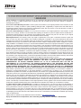
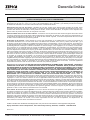
Limited Warranty ............................................................................... 41
Product Registration ...........................................................................42

4
Tidal II Use, Care, and Installation Guide
TIDAL II
WALL
PRO
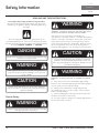
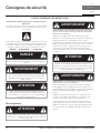
Safety Information
Your safety and the safety of others are very important.
We have provided many important safety messages in this
manual for your appliance. Always read and obey all safety
messages.
This is the Safety Alert Symbol. This symbol alerts you to
potential hazards that can cause severe bodily injury or death.
All safety messages will follow the Safety Alert Symbol and either
the words “DANGER” “WARNING” or “CAUTION”
DANGER
Danger means that failure to heed this safety statement may
result in severe injury or death.
READ AND SAVE THESE INSTRUCTIONS
WARNING - TO REDUCE THE RISK OF FIRE, ELECTRIC SHOCK,
OR INJURY TO PERSONS, OBSERVE THE FOLLOWING:
a) Use this unit only in the manner intended by the
manufacturer. If you have questions, contact the manufacturer.
b) Before servicing or cleaning unit, switch power o at service
panel and lock the service disconnecting means to prevent
power from being switched on accidentally. When the service
disconnecting means cannot be locked, securely fasten a
prominent warning device, such as a tag, to the service panel.
General Safety
WARNING
Warning means that failure to heed this safety statement
may result in extensive product damage, serious personal
injury, or death.
CAUTION
Caution means that failure to heed this safety statement
may result in minor or moderate personal injury, property or
equipment damage.
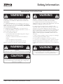
WARNING
To reduce the risk of fire or electric shock, do not use this fan
with any solid-state control device.
WARNING
CAUTION
For General Ventilating Use Only. Do Not Use To Exhaust
Hazardous Or Explosive Materials And Vapors. Take care
when using cleaning agents or detergents. Suitable for use in
household cooking area.
WARNING
WARNING - TO REDUCE THE RISK OF A RANGE TOP GREASE
FIRE:
a) Never leave surface units unattended at high settings.
Boilovers cause smoking and greasy spillovers that may ignite.
Heat oils slowly on low or medium settings.
b) Always turn hood ON when cooking at high heat or
when flambeing food. (i.e. Crepes Suzette, Cherries Jubilee,
Peppercorn Beef Flambe’).
c) Clean ventilating fans frequently. Grease should not be
allowed to accumulate on fan or filter.
d) Use proper pan size. Always use cookware appropriate for
the size of the surface element.

5
Tidal II Use, Care, and Installation Guide
ZEPHYRONLINE.COM
Safety Information
WARNING
READ AND SAVE THESE INSTRUCTIONS
WARNING - TO REDUCE THE RISK OF INJURY TO PERSONS
IN THE EVENT OF A RANGE TOP GREASE FIRE, OBSERVE THE
FOLLOWING:
a) SMOTHER FLAMES with a close-fitting lid, cookie sheet, or
metal tray, then turn o the burner. BE CAREFUL TO PREVENT
BURNS. If the flames do not go out immediately, EVACUATE AND
CALL THE FIRE DEPARTMENT.
b) NEVER PICK UP A FLAMING PAN – You may be burned.
c) DO NOT USE WATER, including wet dishcloths or towels – a
violent steam explosion will result.
d) Use an extinguisher ONLY if:
1) You know you have a Class ABC extinguisher, and you
already know how to operate it.
2) The fire is small and contained in the area where it
started.
3) The fire department is being called.
4) You can fight the fire with your back to an exit
Based on “Kitchen Firesafety Tips” published by NFPA.
WARNING
WARNING
TO REDUCE THE RISK OF FIRE, USE ONLY METAL DUCTWORK.
CAUTION
To reduce risk of fire and to properly exhaust air outside, do
not vent exhaust air into spaces within walls, ceilings, attics,
crawl spaces, or garages.
WARNING
WARNING - TO REDUCE THE RISK OF FIRE, ELECTRIC SHOCK,
OR INJURY TO PERSONS, OBSERVE THE FOLLOWING:
a) Installation work and electrical wiring must be done by
qualified person(s) in accordance with all applicable codes and
standards, including fire-rated construction.
b) Sucient air is needed for proper combustion and
exhausting of gases through the flue (chimney) of fuel burning
equipment to prevent back drafting. Follow the heating
equipment manufacturer’s guideline and safety standards such
as those published by the National Fire Protection Association
(NFPA), and the American Society for Heating, Refrigeration
and Air Conditioning Engineers (ASHRAE), and the local code
authorities.
c) When cutting or drilling into wall or ceiling, do not damage
electrical wiring and other hidden utilities.
d) Ducted fans must always be vented to the outdoors.
e) If this unit is to be installed over a tub or shower, it must be
marked as appropriate for the application and be connected
to a GFCI (Ground Fault Circuit Interrupter) - protected branch
circuit.
WARNING
Prop. 65 Warning for California Residents: This product may
contain chemicals known to the State of California to cause
cancer, birth defects, or other reproductive harm.

6
Tidal II Use, Care, and Installation Guide
TIDAL II
WALL
PRO
Safety Information
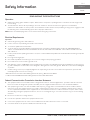
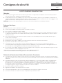
Operation
Ź Always leave safety grilles and filters in place. Without these components, operating blowers could catch onto hair, fingers and
loose clothing.
Ź The manufacturer declines all responsibility in the event of failure to observe the instructions given here for installation,
maintenance and suitable use of the product. The manufacturer further declines all responsibility for injury due to negligence and
the warranty of the unit automatically expires due to improper maintenance.
NOTE: Please check www.zephyronline.com for revisions before doing any custom work.
Electrical Requirements
Important:
Ź Observe all governing codes and ordinances.
Ź It is the customer’s responsibility to be aware of these below:
Ź To contact a qualified electrical installer.
Ź To assure that the electrical installation is adequate and in conformance with National Electrical Code, ANSI/NFPA 70 latest
edition* or CSA standards C22.1-94, Canadian Electrical Code, Part 1 and C22.2 No.0-M91 - latest edition** and all local codes
and ordinances.
Ź If codes permit and a separate ground wire is used, it is recommended that a qualified electrician determine that the ground path
is adequate.
Ź Do not ground to a gas pipe.
Ź Check with a qualified electrician if you are not sure the range hood is properly grounded.
Ź Do not have a fuse in the neutral or ground circuit.
Ź This appliance requires a 120V 60Hz electrical supply and connected to an individual properly grounded branch circuit protected
by a 15 or 20 ampere circuit breaker or time delay fuse. Wiring must be 2 wire with ground. Please also refer to Electrical Diagram
on product.
Ź A cable locking connector (not supplied) might also be required by local codes. Check with local requirements, purchase and
install appropriate connector if necessary.
* National Fire Protection Association Batterymarch Park, Quincy, Massachusetts 02269
** CSA International 8501 East Pleasant Valley Road, Cleveland, Ohio 44131-5575
Federal Communication Commission Interface Statement
Ź This equipment has been tested and found to comply with the limits for a Class B digital device, pursuant to Part 15 of the FCC
Rules. These limits are designed to provide reasonable protection against harmful interference in a residential installation.
Ź This equipment generates, uses and can radiate radio frequency energy and, if not installed and used in accordance with the
instructions, may cause harmful interference to radio communications. However, there is no guarantee that interference will not
occur in a particular installation. If this equipment does cause harmful interference to radio or television reception, which can be
determined by turning the equipment o and on, the user is encouraged to try to correct the interference by one of the following
measures:
Ź Reorient or relocate the receiving antenna.
Ź Increase the separation between the equipment and receiver.
Ź Connect the equipment into an outlet on a circuit dierent from that to which the receiver is connected.
Ź Consult the dealer or an experienced radio/TV technician for help.
READ AND SAVE THESE INSTRUCTIONS

7
Tidal II Use, Care, and Installation Guide
ZEPHYRONLINE.COM
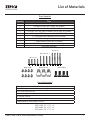
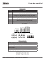
List of Materials
Parts Not Supplied
Ducting, conduit and all installation tools
Cable locking connector (if required by local codes)
Duct cover extension kit
Recirculating kit
RF remote control
Dual blower motor
Wood board to hang hood (WxDxH)
AK7400AS: 27” x 1/2” x 4”
AK7436AS: 33” x 1/2” x 4”
AK7448AS : 45” x 1/2” x 4”
Parts Supplied
Quantity Part
1Hood
2 Pro bae filters (AK7400AS, AK7436AS)
3 Pro bae filters (AK7448AS)
2 LumiLight LED, 6W (pre-installed) (AK7400AS, AK7436AS)
4 LumiLight LED, 6W (pre-installed) (AK7448AS)
1 8” round backdraft damper (pre-installed)
1 3-1/4” x 10” rectangular collar with damper
1 Single blower motor (pre-installed)
1 Top cover plate (for horizontal ducting)
1 Hardware package
#6 x 1” (4 )
#6 x 1-1/2” (4 )
#6 x 2” (4 )
M3.5 x 8 (8)
Wire Caps (3)
3/16 x 3/8 (4)

8
Tidal II Use, Care, and Installation Guide
TIDAL II
WALL
PRO
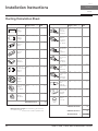
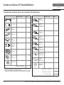
Installation Instructions
Duct pieces
To t al
Equivalent number
length x used =
3- 1/ 4” x 10”
Rect.,
straight
1 Ft. x ( ) =
Ft.
3- 1/ 4” x 10”
Rect. to
6” round
transition
5 Ft. x ( ) =
Ft.
3- 1/ 4” x 10”
Rect. to
6” round
transition
90
0
elbow
20 Ft. x ( ) =
Ft.
6”, 7”, 8”, 10”
Round,
90
0
15 Ft.
x ( ) =
Ft.
6”, 7”, 8”, 10”
Round,
45
0
9 Ft. x ( ) =
Ft.
Ft.
6”, 7”, 8”, 10”
Round,
straight
1 Ft. x ( ) =
Ft.
Subtotal column 1 =
Duct pieces
To t al
Equivalent number
length x used =
6”, 7”, 8”, 10”
Round, wall
cap with
damper
30 Ft. x ( ) =
Ft.
Ft.
Ft.
Ft.
6”, 7”, 8”, 10”
Round
roof cap
30 Ft. x ( ) =
Ft.
Subtotal column 2 =
Subtotal column 1 =
Total ductwork =
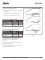
Maximum Duct Length: For satisfactory air movement,
the total duct length
should not exceed 150 equivalent feet.
6” round to
3- 1/ 4” x 10”
rect.
transition
1 Ft. x ( ) =
Ft.
6” round to
3- 1/ 4” x 10”
rect.
transition
90
0
elbow
16 Ft. x ( ) =
Ft.
7” round to
3 1/ 4” x 10”
rect.
transition
8 Ft. x ( ) =
Ft.
7” round to
3- 1/ 4” x 10”
rect.
transition
90
0
elbow
23 Ft. x ( ) =
Ft.
elbow
elbow
7” to 6” or
8” to 7” Round
tapered
reducer
25 Ft. x ( ) =
Ft.
3- 1/ 4” x 10”
Rect. 90
0
elbow
15 Ft. x ( ) =
Ft.
3- 1/ 4” x 10”
Rect. 45
0
elbow
9 Ft. x ( ) =
Ft.
3- 1/ 4” x 10”
Rect. 90
0
flat elbow
24 Ft. x ( ) =
Ft.
3- 1/ 4” x 10”
Rect.
wall cap
with damper
30 Ft. x ( ) =
Ft.
Ft. x ( ) =
Ft.
15
6”, 7“, 8”
Round
in-line
damper
Ducting Calculation Sheet

9
Tidal II Use, Care, and Installation Guide
ZEPHYRONLINE.COM
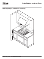
Installation Instructions
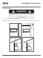
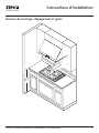
Mounting Height, Clearance, & Ducting
24” min.
34” max.
36”

10
Tidal II Use, Care, and Installation Guide
TIDAL II
WALL
PRO
Installation Instructions
Mounting Height, Clearance, & Ducting
A minimum of 8” round duct or 3-1/4” x 10” rectangular duct is recommended to maintain maximum
air flow eciency for single blower and 10” round duct for dual internal blower for both vertical and
horizontal ducting.
Always use rigid type metal ducts only. Flexible ducts could restrict air flow by up to 50%.
Also use the ducting calculation sheet (on page 11) to compute total available duct run when using
elbows, transitions and caps.
ALWAYS, when possible, reduce the number or transitions and turns. If long duct run is required,
increase duct size from 8” to 10”.
If turns or transitions are required; install as far away from hood duct output and as far apart,
between the two as possible.
Minimum mount height between range top to hood bottom should be no less than 24”.
Maximum mount height should be no higher than 34”.
It is important to install the hood at the proper mounting height. Hoods mounted too low could result
in heat damage and fire hazard; while hoods mounted too high will be hard to reach and will lose its
performance and eciency.
If available, also refer range manufacturer’s height clearance requirements and recommended hood
mounting height above range. Always check your local codes for any dierences.
Duct cover extension kit available for ceiling heights up to 12 feet. Turn to the list of parts and
accessories section for part number and ordering information.
For shipment and installation damages:
Ź Please fully inspect unit for damage before installation.
Ź If the unit is damaged in shipment, return the unit to the store in which it was bought for repair or
replacement.
Ź If the unit is damaged by the customer, repair or replacement is the responsibility of the customer.
Ź If the unit is damaged by the installer (if other than the customer), repair of replacement must be
made by arrangement between customer and installer.

11
Tidal II Use, Care, and Installation Guide
ZEPHYRONLINE.COM
Installation Instructions
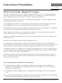
Ducting Options
Ź Use single wall rigid metal ductwork only.
Ź Fasten all connections with sheet metal screws and tape all joints w/ certified Silver Tape or Duct
Tape.
Fire Hazard: NEVER exhaust air or terminate ductwork into
spaces between walls, crawl spaces, ceilings, attics, or garages.
All exhaust must be ducted to the outside, unless using the
recirculating option.
WARNING
Sot or crawl space
Roof Pitch w/
Flashing & Cap
Rear Ducting
Side wall cap
w/ gravity damper
ductless
recirculating

12
Tidal II Use, Care, and Installation Guide
TIDAL II
WALL
PRO
Installation Instructions
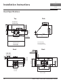
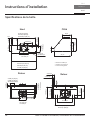
Ů
27-7/8” (30“)
33-7/8” (36”)
45-13/16” (48”)
1-1/8”
8-9/16”
1”
6”
11-9/16”
2-5/8”
*7-3/4”
**9-15/16”
29-15/16” (30“)
35-7/8” (36”)
47-7/8” (48”)
3-3/8” (30“)
6-3/8” (36”)
12-3/8” (48”)
1-11/16”
12”
18”
12-9/16”
24”
4”
Top
Back
Side
*9-1/2”
**14-3/16”
*7-7/8”
**10-3/8”
*7-7/8”
**10-3/8”
***3-3/16”
*9-1/2”
**14-3/16”
***9-7/8”
* 8” round ducting
** 10” round ducting
*** Rectangular ducting
27-3/8” (30“, 36”)
35-1/4” (48”)
18”
5-1/4”
21-1/4”
13-9/16”
16-1/8”
3-1/4”
1-11/16”
Back

13
Tidal II Use, Care, and Installation Guide
ZEPHYRONLINE.COM
Installation Instructions
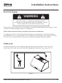
Electrical Supply
Electrical wiring must be done by qualified person(s) in
accordance with all applicable codes and standards. Turn o
electrical power at service entrance before wiring.
WARNING
For personal safety, remove house fuse or open circuit breaker before beginning installation. Do not
use extension cord or adapter plug with this appliance.
Follow national electrical codes or prevailing local codes and ordinances.
This appliance requires a 120V 60Hz electrical supply, and connected to an individual, properly
grounded branch circuit, protected by a 15 or 20 ampere circuit breaker or time delay fuse. Wiring
must be 2 wire w/ ground. Please also refer to the Electrical Diagram labeled on product.
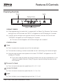
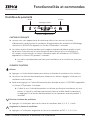
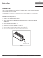
Cable Lock
A cable locking connector (not supplied) might be required by local codes. Check with local
requirements and codes, purchase and install appropriate connector if necessary. (FIG. A)
Cable Lock
FIG. A

14
Tidal II Use, Care, and Installation Guide
TIDAL II
WALL
PRO
Installation Instructions
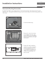
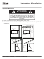
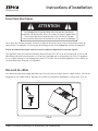
Horizontal Ducting Conversion
By default the Tidal II is pre-configured for 8” round vertical ducting. These steps are for 8” round
and 3-1/4”x10” rectangular horizontal ducting. If you are continuing with vertical ducting, please skip
these steps.
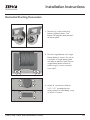
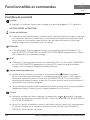
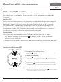
3. Using a flat-head screwdriver,
remove the smaller rectangular
knock-out plate (A) for 3-1/4” x
10” rectangular ducting or the
larger knock-out plate (B) for 8”
round ducting located on the
back of hood.
1. Disconnect blower plug.
2. Remove (4) screws from interior
of hood body attaching single
blower plate to top of hood body.
Remove single blower and single
blower plate.
A
B

15
Tidal II Use, Care, and Installation Guide
ZEPHYRONLINE.COM
Installation Instructions
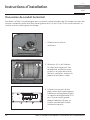
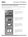
Horizontal Ducting Conversion
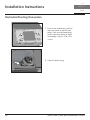
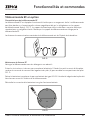
4. Remove (4) screws attaching
blower to blower plate. Turn
blower 180 degrees and reattach
to blower plate.
5. Position single blower with single
blower plate as shown. Be sure to
tuck back of single blower plate
into tabs at back of hood. Secure
single blower plate to back of
hood using (4) screws removed
from step 2.
6. Attach 8” round duct collar or
3-1/4” x 10” rectangular duct
collar to back of hood body using
(4) M3.5 x 8 screws.

16
Tidal II Use, Care, and Installation Guide
TIDAL II
WALL
PRO
Installation Instructions
Horizontal Ducting Conversion
7. From inside hood body, position
top cover plate to top of hood
body. From outside hood body,
attach top cover plate to top of
hood body using (4) 3/16 x 3/8
screws.
8. Connect blower plug.

17
Tidal II Use, Care, and Installation Guide
ZEPHYRONLINE.COM
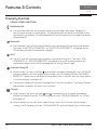
Installation Instructions
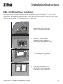
PBD-1300B Dual Blower Installation
This range hood is equipped standard with a single blower vertical duct option. To convert from
single blower vertical ducting to dual blower vertical ducting please following the instructions below.
PBD-1300B dual blower kit is compatible with all Tidal II sizes.
1. Remove the bae filters and
if applicable, remove the side
panels. Disconnect blower plug.
2. Remove (4) screws at top of
hood body attaching blower to
blower plate. Remove blower from
interior of hood body.
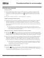
3. Remove (4) screws from interior
of hood body attaching blower
plate to hood body. Remove
blower plate.
4. Install dual blower plate from
PBD-1300B kit into hood body.
Attach by (4) screws previously
removed from step 3.

18
Tidal II Use, Care, and Installation Guide
TIDAL II
WALL
PRO
Installation Instructions
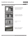
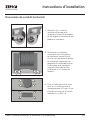
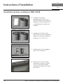
PBD-1300B Dual Blower Installation
5. Install previously removed blower
onto one side of dual blower plate
and attach by (4) previously
removed screws from step 2.
6. Install blower from PBD-1300B
kit onto other side of dual blower
plate by (4) 3/16 x 3/8 screws.
7. Dual blower screw mount
locations.
8. Remove (4) screws to remove the
light panel. Install dual blower
PCB inside the hood body.

19
Tidal II Use, Care, and Installation Guide
ZEPHYRONLINE.COM
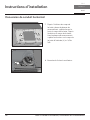
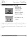
Installation Instructions
PBD-1300B Dual Blower Installation
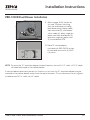
9. Refer to page 32-33 section for
this step. Connect the wiring
from the dual blower including
both blower plugs, blower cable
6 pin connector (E), dual blower
switch cable (H), black single pin
power cord from dual blower (K),
and white single pin power cord
(F) to dual blower PCB.
NOTE: To secure the 10” transition adapter to top of hood a cut out of 14-1/2” width x 10-1/2” depth
will need to be made in the cabinet bottom.
If internal cabinet dimensions prevent this size of a cut out then the 10” transition adapter may be
mounted to the cabinet bottom rather than the top of the hood. Cut out dimensions for this type of
installation are 13-1/4” width x 6-1/4” depth.
10. Place 10” round adapter
(included with PBD-1300B) on top
of hood and secure with (4) M3.5
x 8 screws.

20
Tidal II Use, Care, and Installation Guide
TIDAL II
WALL
PRO
Installation Instructions
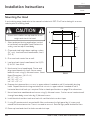
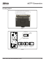
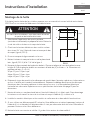
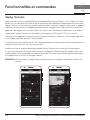
Mounting the Hood
If recirculating range hood refer to the manual included with ZRC-70xxC recirculating kit or on our
website prior to installing hood.
1. Select preferred ducting application (vertical
or horizontal) and prepare hood. Remove the
safety screw on top of hood body.
2. Choose desired height above cooking surface
(24” min). Level and mark hood bottom, line A
(FIG. B)
3. Plum and mark center line on wall.
4. Level and mark top of wood board, line B (FIG.
B) 16-7/8” from line A.
5. Mark center line of wood board. Center and
align top of board with line B. Secure wood
board to studs using (4) #6 wood screws. Wood
Board Dimensions: (W x D x H)
30”: 27” x 1/2” x 4”
36”: 33” x 1/2” x 4”
48”: 45” x 1/2” x 4”
FIG. B
C/L
C/L
A
B
16-7/8”
min
24”
4”
wood board
At least two installers are required due to the
weight and size of the hood.
CAUTION
6. Prepare duct pipe and duct cut outs in upper cabinet if needed or wall if horizontally ducting
hood. Prepare electrical wiring and electrical cut outs in upper cabinet if needed or wall if
horizontal electrical hook up is required. Refer to hood specifications on page 15 for dimensions.
7. Mount hood onto wood board and secure using (4) #6 wood screws. Further secure hood onto wall
through lower body screw holes by (2) #6 wood screws.
8. Install electrical and duct work and seal with certified aluminum duct tape.
9. If using RF remote control, remove bae filters and remove the light panel by (4) screws and
extend the blue antenna wire. There is no need to secure it. Reinstall light panel and bae filters.
10. Power up hood and check for leaks around duct tape.
La page est en cours de chargement...
La page est en cours de chargement...
La page est en cours de chargement...
La page est en cours de chargement...
La page est en cours de chargement...
La page est en cours de chargement...
La page est en cours de chargement...
La page est en cours de chargement...
La page est en cours de chargement...
La page est en cours de chargement...
La page est en cours de chargement...
La page est en cours de chargement...
La page est en cours de chargement...
La page est en cours de chargement...
La page est en cours de chargement...
La page est en cours de chargement...
La page est en cours de chargement...
La page est en cours de chargement...
La page est en cours de chargement...
La page est en cours de chargement...
La page est en cours de chargement...
La page est en cours de chargement...
La page est en cours de chargement...
La page est en cours de chargement...
La page est en cours de chargement...
La page est en cours de chargement...
La page est en cours de chargement...
La page est en cours de chargement...
La page est en cours de chargement...
La page est en cours de chargement...
La page est en cours de chargement...
La page est en cours de chargement...
La page est en cours de chargement...
La page est en cours de chargement...
La page est en cours de chargement...
La page est en cours de chargement...
La page est en cours de chargement...
La page est en cours de chargement...
La page est en cours de chargement...
La page est en cours de chargement...
La page est en cours de chargement...
La page est en cours de chargement...
La page est en cours de chargement...
La page est en cours de chargement...
La page est en cours de chargement...
La page est en cours de chargement...
La page est en cours de chargement...
La page est en cours de chargement...
La page est en cours de chargement...
La page est en cours de chargement...
La page est en cours de chargement...
La page est en cours de chargement...
La page est en cours de chargement...
La page est en cours de chargement...
La page est en cours de chargement...
La page est en cours de chargement...
La page est en cours de chargement...
La page est en cours de chargement...
La page est en cours de chargement...
La page est en cours de chargement...
La page est en cours de chargement...
La page est en cours de chargement...
La page est en cours de chargement...
La page est en cours de chargement...
-
 1
1
-
 2
2
-
 3
3
-
 4
4
-
 5
5
-
 6
6
-
 7
7
-
 8
8
-
 9
9
-
 10
10
-
 11
11
-
 12
12
-
 13
13
-
 14
14
-
 15
15
-
 16
16
-
 17
17
-
 18
18
-
 19
19
-
 20
20
-
 21
21
-
 22
22
-
 23
23
-
 24
24
-
 25
25
-
 26
26
-
 27
27
-
 28
28
-
 29
29
-
 30
30
-
 31
31
-
 32
32
-
 33
33
-
 34
34
-
 35
35
-
 36
36
-
 37
37
-
 38
38
-
 39
39
-
 40
40
-
 41
41
-
 42
42
-
 43
43
-
 44
44
-
 45
45
-
 46
46
-
 47
47
-
 48
48
-
 49
49
-
 50
50
-
 51
51
-
 52
52
-
 53
53
-
 54
54
-
 55
55
-
 56
56
-
 57
57
-
 58
58
-
 59
59
-
 60
60
-
 61
61
-
 62
62
-
 63
63
-
 64
64
-
 65
65
-
 66
66
-
 67
67
-
 68
68
-
 69
69
-
 70
70
-
 71
71
-
 72
72
-
 73
73
-
 74
74
-
 75
75
-
 76
76
-
 77
77
-
 78
78
-
 79
79
-
 80
80
-
 81
81
-
 82
82
-
 83
83
-
 84
84


Yes AK7400AS Manuel utilisateur
- Catégorie
- Hottes
- Taper
- Manuel utilisateur
dans d''autres langues
- English: Yes AK7400AS User manual
Documents connexes
Autres documents
-
Kyosho CA0506 Manuel utilisateur
-
 Trifecte TRI-RS-8190F2 Manuel utilisateur
-
 Trifecte TRI-RS-8190F2 Manuel utilisateur
-
Zephyr AK7548CS Manuel utilisateur
-
Pioneer VSX-LX304 Manuel utilisateur
-
-
-
Zephyr AK9334BS Guide d'installation
-
XO IL4819KSE 48 Inch Range Hood Insert Manuel utilisateur
-
 Trifecte TRI-RS-7275F1 Manuel utilisateur


