
Model CC45
ENGLISH............................................2
FRANÇAIS.......................................21
ESPAÑOL.........................................41
In USA - BEST Hartford, Wisconsin
In CANADA - BEST Drummondville, QC, Canada
REGISTER YOUR PRODUCT ONLINE AT : www.BestRangeHoods.com/register
For additional Information visit www.BestRangeHoods.com

- 2 -
READ AND SAVE THESE INSTRUCTIONS
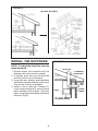
WARNING
TO REDUCE THE RISK OF FIRE, ELECTRIC SHOCK, OR INJURY TO PERSONS,
OBSERVE THE FOLLOWING:
1. Use this unit only in the manner intended by the manufacturer. If you have questions,
contact the manufacturer at the address or telephone number listed in the warranty.
2. Before servicing or cleaning unit, switch power off at service panel and lock service
panel to prevent power from being switched on accidentally. When the service
disconnecting means cannot be locked, securely fasten a prominent warning device,
such as a tag, to the service panel.
3. Installation work and electrical wiring must be done by a qualified person(s) in accor-
dance with all applicable codes and standards, including fire-rated construction codes
and standards.
4. Sufficient air is needed for proper combustion and exhausting of gases through the flue
(chimney) of fuel burning equipment to prevent backdrafting. Follow the heating equip-
ment manufacturer’s guidelines and safety standards such as those published by the
National Fire Protection Association (NFPA), and the American Society for Heating,
Refrigeration and Air Conditioning Engineers (ASHRAE), and the local code authorities.
5. When cutting or drilling into wall or ceiling, do not damage electrical wiring and other
hidden utilities.
6. Ducted fans must always be vented to the outdoors.
7. Do not use this unit with any separate solid-state speed control device.
8. To reduce the risk of fire, use only metal ductwork.
9. This unit must be grounded.
10. When applicable local regulations require more restrictive installation and/or certification
requirements, the aforementioned requirements prevail this document and the installer
agrees to conform to these requirements at his own expenses.
TO REDUCE THE RISK OF A RANGE TOP GREASE FIRE:
A. Never leave surface units unattended at high settings. Boilovers cause smoking and
greasy spillovers that may ignite. Heat oils slowly on low or medium settings.
B. Always turn hood ON when cooking at high heat or when cooking flambeing foods. (i.e.
Crêpes Suzette, Cherries Jubilee, Peppercorn Beef Flambé).
C. Clean ventilating fans frequently. Grease should not be allowed to accumulate on fan or
filter.
D. Use proper pan size. Always use cookware appropriate for the size of the surface
element.
WARNING
TO REDUCE THE RISK OF INJURY TO PERSONS IN THE EVENT OF A RANGE TOP
GREASE FIRE, OBSERVE THE FOLLOWING:*
1. SMOTHER FLAMES with a close-fitting lid, cookie sheet, or metal tray, then turn off the
burner. BE CAREFUL TO PREVENT BURNS. IF THE FLAMES DO NOT GO OUT
IMMEDIATELY, EVACUATE AND CALL THE FIRE DEPARTMENT.
2. NEVER PICK UP A FLAMING PAN - You may be burned.
3. DO NOT USE WATER, including wet dishcloths or towels - This could cause a violent
steam explosion.
4. Use an extinguisher ONLY if:
A. You own a Class ABC extinguisher and you know how to operate it.
B. The fire is small and contained in the area where it started.
C. The fire department has been called.
D. You can fight the fire with your back to an exit.
* Based on “Kitchen Fire Safety Tips” published by NFPA.
!
INTENDED FOR DOMESTIC COOKING ONLY
!

- 3 -
!
CAUTION
1. For indoor use only.
2. To reduce risk of fire and to properly exhaust air, be sure to duct air outside. Do not vent
exhaust air into spaces within walls or ceilings or into attics, crawl spaces, or garages.
3. Take care when using cleaning agents or detergents.
4. Avoid using food products that produce flames under the Range Hood.
5. For general ventilating use only. Do not use to exhaust hazardous or explosive mate-
rials and vapors.
6. To avoid motor bearing damage and noisy and/or unbalanced impellers, keep drywall
spray, construction dust, etc. off power unit.
7. Your hood motor has a thermal overload which will automatically shut off the motor if it
becomes overheated. The motor will restart when it cools down. If the motor continues
to shut off and restart, have the hood serviced.
8. For best capture of cooking impurities, the bottom of the hood should be a minimum of
24" and a maximum of 30" above the cooking surface.
9. Two installers are recommended because of the large size and weight of this hood.
10. Please read specification label on product for further information and requirements.
11. Automatically operated device. To reduce the risk of injury, disconnect power before
servicing.
12. EXTERNAL BLOWER MODELS ONLY: To reduce risk of fire and electric shock, install
this range hood only with Best Exterior Blower Models EB6, EB9, EB12 or EB15 or Best
In-Line Blower Models ILB3, ILB6, ILB9 or ILB11. Other blowers cannot be substituited.
(Blower sold separately)

- 4 -
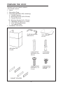
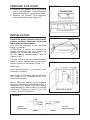
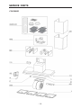
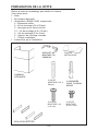
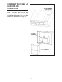
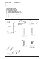
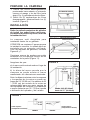
PREPARE THE HOOD
Unpack hood and check contents.
You should receive:
1 - Hood
1 - Decorative Flues
1 - Parts Bag (B080811045) containing:
4 - Cabinet Spacers
2 - Mounting Screws (4.8 x 38 mm)
2 - Drywall Anchors
12 - Mounting Screws (4.2 x 15 mm)
2 - Mounting Screws (3.9 x 6 mm)
2 - Flue Mounting Brackets
1 - Top cabinet Plate
1 - Installation Instructions
2 MOUNTING
SCREWS (4.8 x
38 mm)
2 DRYWALL
ANCHORS
DECORATIVE
FLUES
CABINET SPACERS
12 MOUNTING
SCREWS (4.2 x
15 mm)
2 MOUNTING
SCREWS (3.9
x 6 mm)
FLUE MOUNTING
BRACKETS
TOP CABINET
PLATE

- 5 -
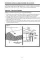
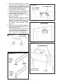
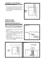
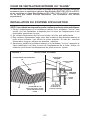
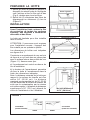
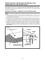
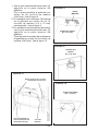
EXTERIOR AND IN-LINE BLOWER SELECTION
CAUTION: To reduce risk of fire and electric shock, install this range hood only with
Best Exterior Blower Models EB6, EB9, EB12 or EB15, and Best In-Line Blower
Models ILB3, ILB6, ILB9 or ILB11. Other blowers cannot be substituited.
INSTALL THE DUCTWORK
NOTE: To reduce the risk of fire, use only metal ductwork.
1. Choose the location where the Exterior Blower or In-Line Blower will be mounted.
See illustrations below for mounting location suggestions and restrictions.
2. A straight, short duct run will allow the hood to perform most efficiently.
3. Long duct runs, elbows and transitions will reduce the performance of the
hood. Use as few of them as possible. Larger ducting may be required for best
performance with long duct runs.
4. After the Exterior or In-Line Blower has been installed, connect round metal
ductwork and work back towards the hood location. Use duct tape to seal joints
between ductwork sections.
OK
OK
SUGGESTED MOUNTING LOCATIONS
EXTERIOR BLOWER
CAUTION: MAY NOT FIT
UNDER EAVES OF SINGLE
STORY HOMES
EXTERIOR
BLOWER
EXTERIOR
BLOWER
10”
ROUND DUCT
HOOD
ROUND
ELBOW
24” TO 30” ABOVE
COOKING SURFACE
FIGURE 1

- 6 -
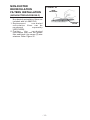
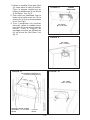
IN-LINE BLOWER
INSTALL THE DUCTWORK
NOTE: To reduce the risk of fire, use only
metal ductwork.
1. Decide where the ductwork will run
between the hood and the outside.
2. A straight, short duct run will allow the
hood to perform most efficiently.
3. Long duct runs, elbows, and transitions
will reduce the performance of the hood.
Use as few of them as possible.
4. Install a roof or wall cap. Connect 10"
round metal ductwork to cap and work
back towards hood location. Use duct
tape to seal the joints between ductwork
sections (Fig.3).
FIGURE 3
ROOF CAP
6” MINIMUM
ROUND DUCT
HOOD
WALL
CAP
ROUND
ELBOW
24” TO 30” ABOVE
COOKING SURFACE
FIGURE 2

- 7 -
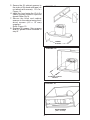
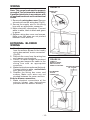
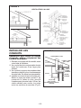
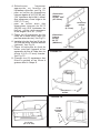
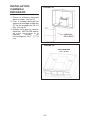
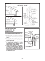
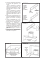
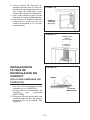
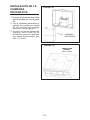
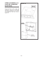
PREPARE THE HOOD
1. Remove the grease filters by pulling
down in the filter latch, and pull the filter
downwards (Fig. 4); repeat for all filters.
2. Remove (2) grease filter spacers,
unscrewing (4) screws (Figure 5).
FIGURE 4
FIGURE 5
INSTALLATION
Remove the plastic protective film from all
exterior surfaces, decorative flues and
filters, prior to final installation
The hood is intended to be installed
inside a cabinet.
ATTENTION: 2 people are required for
proper installation; the unit should be
installed by a qualified operator.
For the cabinet measurements, refer to
Figure 6 and 7.
For new construction it is recommended to
install a wood support that is flush with
interior surface of wall studs (Figure 11 ).
Make sure:
a)the wood support is centered over
installation location.
b)the height of the wood support will allow
the hood to be installed within the
dimensions shown.
Notes: Minimum cabinet hood distance
above cook top must not be less than 24”. A
maximum of 30” above cook top is highly
recommended for best capture of cooking
impurities. Distances over 30” are the
installer and user discretion.
FIGURE 6
from 16.5 to 28.1”
13”
from 34.5 to 34.75”
12.7”
16.34”
FIGURE 7
Top view
(ducted hood)
Top view
(non-ducted hood)
7.95”
4.37”
3.98”
ø6.29”
4.37”
GREASE FILTERS
GREASE FILTER
SPACERS
FRONT
FRONT

- 8 -
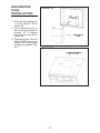
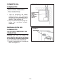
1. Use the supplied template to make
(4) holes in the upper part of the
cabinet. Secure top cabinet plate to
the cabinet by means (4) 4.2x15mm
wood screws. Refer Figure 8.
2. Only NON-DUCTED HOODS:
Install the flange to the cabinet by
means (3) wood screws (4.2 x 15
mm) supplied. Refer Figure 9.
3. FOR DECORATIVE FLUE
INSTALLATION:
Use the supplied template to make
(2) holes in the upper part of the
cabinet. Secure flue mounting
bracket to the cabinet by means (4)
4.2x15mm wood screws. Refer
Figure 10.
4. Select the correct cabinet spacers
according to the inside width of the
cabinet, refer Fig.12:
- for cabinets with an inside width of
34.5”, use 0.28” wide spacers.
- for cabinets with an inside width of
34.75”, use 0.40” wide spacers.
FIGURE 8
WOOD SCREWS
(4.2 x 15 mm)
TOP CABINET PLATE
FRAMING BEHIND WOOD
CROSS SUPPORT
WOOD SUPPORT
BEHIND DRYWALL
DRYWALL
FIGURE 11
0.28”
inside
cabinet
width
34.5”
0.4”
inside
cabinet
width
34.75”
FIGURE 12
CABINET
SPACERS
FIGURE 9
WOOD SCREWS
(4.2 x 15 mm)
FIGURE 10
WOOD SCREWS
(4.2 x 15 mm)

- 9 -
MOUNTING SCREWS
4.8x38mm
FIGURE 13
FIGURE 14
CABINET
SPACERS
5. Secure the (2) cabinet spacers to
the sides of the hood with tape (do
not attach with screws). Refer
Figure 13.
6. Install the hood using the (2) 4.8 x
38mm screws anchors optional
drywall. Refer Fig.14.
7. Secure the hood and cabinet
spacers to the cabinet using the 4
wood screws (4.2 x 15 mm)
supplied.
Refer Figure 15.
8. Replace (2) grease filter spacers
and (4) grease filters removed in
step 2.
FIGURE 15
WOOD SCREWS
(4.2 x 15 mm)

- 10 -
CONNECT DUCTWORK
(DUCTED HOODS ONLY)
1. Use 8" round metal duct to connect
the discharge collar on the hood to
the ductwork above. Refer Figure 16.
2. Use duct tape to make all joints secure
and air tight.
FIGURE 16
Ø 8”
ROUND
METAL
DUCT
NON-DUCTED
INSTALLATION
(NON-DUCTED HOODS ONLY)
When used in recirculation mode, To
Reduce the Risk of Fire and Shock use
only conversion kit Model ANKCC45.
1. Install the adapter on the air outlet. Refer
Figure 17.
2. Refer to Figure 18. Connect 6” round
duct to the discharge opening so that
the air is sent outside the cabinet and
sent back into the room.
3. Use duct tape to make all joints secure
and air tight.
4. Refer to Figure 19. Install the non-
ducted grid by means (2) wood screws
(4.2 x 15 mm) supplied.
FIGURE 17
ADAPTER
Ø 6”
ROUND
DUCT
FIGURE 19
WOOD SCREWS
(4.2 x 15 mm)
FIGURE 18

- 11 -
FIGURE 20
CHARCOAL
FILTER
WIRE
RETAINERS
NON-DUCTED
RECIRCULATION
FILTERS INSTALLATION
(NON-DUCTED HOODS ONLY)
Non-ducted recirculation filters are
included with kit ANKCC45.
1. Replacement non-ducted
recirculation filters can be
purchased separately
(AECC45SB).
2. Position the non-ducted
recirculation filter over the grease
filter and block it by means (2) wire
retainers. Refer Figure 20.

- 12 -
WIRING
Note: This range hood must be properly
grounded. The unit should be installed by
a qualified electrician in accordance with
all applicable national and local electrical
codes.
1. Remove the wiring box cover. Remove
a knockout from the wiring box (Fig.21).
2. Secure the supply wire to the wiring
box with an appropriate connector.
3. Make electrical connections. Connect
white to white, black to black and green
to green.
4. Replace wiring box cover and screws.
Make sure that wires are not pinched
between cover and box.
EXTERNAL BLOWER
WIRING
1. Run 2-wire plus ground power cable
from the exterior blower to the hood’s
wiring box marked “motor connection”
(Fig.22).
2. Remove the cover from the wiring box
and remove one knockout.
3. Feed 6” of cable through the knockout
opening and secure the cable to the
wiring box with an appropriate
connector.
4. Make electrical connections at the hood.
Connect white-to-white, red-to-black
and green-to-ground.
5. Replace the wiring box cover and
screws. Make sure wires are not
pinched between the cover and box.
Exterior blower connection:
1. Make electrical connections at the
exterior blower (see instructions
provided with the exterior blower).
WIRING BOX
COVER
FIGURE 21
EXTERIOR BLOWER
OR “IN-LINE”
CONNECT:
WHITE-TO-WHITE,
RED-TO-BLACK,
GREEN-TO-GROUND.
FIGURE 22
BOX MARKED
“MOTOR
CONNECTION”

- 13 -
DECORATIVE
FLUE
INSTALLATION
1. Place the decorative flue
in to the cabinet. Refer
Figure 23.
2. Fix the decorative flue to
the mounting bracket by
means (2) 3.9x6mm
mounting screws.Refer
Figure 24.
3. Purchase Upper Flue Kit
AECC45SB from your
dealer if the inside height
of cabinet is greater than
28.1”.
FIGURE 23
DECORATIVE
FLUE
FIGURE 24
MOUNTING SCREWS
(3.9 x 6 mm)

- 14 -
FIGURE 25
MAINTENANCE
Proper maintenance of the Range Hood
will assure proper performance of the unit.
BEFORE SERVICING OR CLEANING
UNIT, SWITCH POWER OFF AT SERVICE
PANEL AND LOCK SERVICE
DISCONNECTING MEANS TO PREVENT
POWER FROM BEING SWITCHED ON
ACCIDENTALLY.
WHEN THE SERVICE DISCONNECTING
MEANS CANNOT BE LOCKED,
SECURELY FASTEN A PROMINENT
WARNING DEVICE, SUCH AS A TAG, TO
THE SERVICE PANEL.
Grease filters
The grease filters should be cleaned periodically depending upon use
(approximately every two (2) months).
Use a warm detergent solution. Grease filters are dishwasher safe.
Clean all-
metal filters in the dishwasher using a non-phosphate detergent. Discoloration
of the filter may occur if using phosphate detergent or as a result of local water
conditions — but this will not affect filter performance. This discoloration is not
covered by the warranty.
To remove the grease filters, pull down on the filter latch and pull the filter
downwards (Fig. 25); remove the other filter in the same way.
Non-ducted recirculation filters
The charcoal filters should be changed every 3/6 months. Remove the wire
retainers and replace non-ducted recirculation filters.
Hood Cleaning
Stainless steel is one of the easiest materials to keep clean. Occasional care will
help preserve its fine appearance.
Cleaning tips:
• Hot water with soap or detergent is all that is usually needed.
• Follow all cleaning by rinsing with clear water. Wipe dry with a clean, soft cloth to
avoid water marks.
• For discolorations or deposits that persist, use a non-scratching household cleanser
or stainless steel polishing powder with a little water and a soft cloth.
• For stubborn cases, use a plastic scouring pad or soft bristle brush together with
cleanser and water. Rub lightly in direction of polishing lines or "grain" of the
stainless finish. Avoid using too much pressure which may mar the surface.
• DO NOT allow deposits to remain for long periods of time.
• DO NOT use ordinary steel wool or steel brushes. Small bits of steel may adhere
to the surface causing rust.
• DO NOT allow salt solutions, disinfectants, bleaches, or cleaning compounds to
remain in contact with stainless steel for extended periods. Many of these com-
pounds contain chemicals which may be harmful. Rinse with water after expo-
sure and wipe dry with a clean cloth.
• Surfaces should be cleaned with warm water and mild detergent only.
GREASE FILTERS

- 15 -
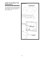
HOW TO ACCESS THE
WIRING BOX
For access to the wiring boxes,
remove decorative flue unscrewing
(2) 3.9x6mm mounting screws.
Refer Figure 26.
DECORATIVE
FLUE
FIGURE 26
MOUNTING SCREWS
(3.9 x 6 mm)
WIRING BOX

- 16 -
OPERATION
Note: Avoid using food products that produce flames under the range
hood.
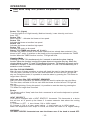
Button TC1 (Lights)
Turns the lights on to High intensity, Medium intensity, Lower intensity, and turns
them OFF.
Button TC2
Motor ON/OFF - Activates the blower at low speed.
Button TC3
Activates the blower at medium low speed.
Button TC4
Activates the blower at medium high speed.
Button TC5
Activates the motor at 4th speed.
Button TC6 (TIMER auto power off 10 min.)
Activates the TIMER function at the blower speed that has already been selected. If the
blower is NOT active, it switches on the blower at the low speed and activates the TIMER
function When the TIMER function is active, TC6 light will blink.
Cleaning Mode
Pressing TC1 and TC6 simultaneously for 2 seconds to activate the glass cleaning
function. When the function is active the system does not recognize any key. When the
cleaning Mode is active TC1 and TC6 backlight will stay on. The function will remain on for
maximum 5 minutes. To exit the Cleaning Mode press TC1 and TC6 simultaneously for 2
seconds or wait 5 minutes.
30h filter CLEAN REMINDER
After 30 hours of blower operation, an alarm will signal the need to clean the grease filters.
The filter alarm, activates for 30 sec each time the blower is turned off and TC6 light will
stay on. During this period, it is possible to reset the alarm by pressing the TC6 button for
longer than a second.
120h non duct filter REPLACEMENT REMINDER
After 120 hours of operation, an alarm will signal the need to replace the non duct filters.
The filter alarm, activates for 30 sec each time the blower is turned off and TC6 light will
stay on:
TC6 lighting blinking. During this period, it is possible to reset the alarm by pressing the
TC6 button for longer than a second.
Buzzer
The Buzzer emits a "beep" each time that a command is set from the keyboard or optional
remote control.
HEAT SENTRY™
Your hood is equipped with a HEAT SENTRY™ thermostat. This thermostat is a device
that will turn on or speed up the blower if it senses excessive heat above the cooking
surface.
1) If blower is OFF - it turns blower ON to HIGH speed.
2) If blower is ON at a lower speed setting - it turns blower up to HIGH speed.
When the temperature level drops to normal, the blower will return to its original setting.
WARNING
The HEAT SENTRY thermostat can start the blower even if the hood is turned OFF.
TC1 TC2
TC3
TC4 TC5 TC6

- 17 -
WARRANTY
ONE YEAR LIMITED WARRANTY FOR BEST PRODUCTS
Broan-NuTone LLC (Broan-NuTone) warrants to the original consumer purchaser of Best products that such products will
be free from defects in materials or workmanship for a period of one year from the date of original purchase. THERE ARE
NO OTHER WARRANTIES, EXPRESS OR IMPLIED, INCLUDING, BUT NOT LIMITED TO, IMPLIED WARRANTIES OR
MERCHANT ABILITY OR FITNESS FOR A PARTICULAR PURPOSE.
During this one-year period, Broan-NuTone will, at its option, repair or replace, without charge, any product or part which is
found to be defective under normal use and service.
THIS WARRANTY DOES NOT EXTEND TO FLUORESCENT LAMP STARTERS, TUBES, HALOGEN AND INCANDES-
CENT BULBS, FUSE, FILTERS, DUCTS, ROOF CAPS, WALL CAPS AND OTHER ACCESSORIES FOR DUCTING.
This warranty does not cover (a) normal maintenance and service or (b) any products or parts which have been subject to
misuse, negligence, accident, improper maintenance or repair (other than by Broan-NuTone), faulty installation or installation
contrary to recommended installation instructions.
The duration of any implied warranty is limited to the one-year period as specified for the express warranty. Some states do
not allow limitation on how long an implied warranty lasts, so the above limitation may not apply to you.
BROAN-NUTONE'S OBLIGATION TO REPAIR OR REPLACE, AT BROAN-NUTONE'S OPTION, SHALL BE THE
PURCHASER'S SOLE AND EXCLUSIVE REMEDY UNDER THIS WARRANTY. BROAN-NUTONE SHALL NOT BE
LIABLE FOR INCIDENTAL, CONSEQUENTIAL OR SPECIAL DAMAGES ARISING OUT OF OR IN CONNECTION WITH
PRODUCT USE OR PERFORMANCE. Some states do not allow the exclusion or limitation of incidental or consequential
damages, so the above limitation or exclusion may not apply to you.
This warranty gives you specific legal rights, and you may also have other rights, which vary from state to state. This warranty
supersedes all prior warranties.
To qualify for warranty service, you must (a) notify Broan-NuTone at the address stated below or telephone number stated
below, (b) give the model number and part identification and (c) describe the nature of any defect in the product or part. At
the time of requesting warranty service, you must present evidence of the original purchase date.
In USA - Best®, 926 W. State Street, Hartford, WI 53027 (800-558-1711)
In Canada - Best®, 550 Lemire Blvd., Drummondville, QC J2C 7W9 (866-737-7770)
www.BestRangeHoods.com
When this occurs, it is impossible to turn the blower OFF with its switch. If you
must stop the blower, do it from the main electrical panel.
LIGHTING
If the light led is damaged, it must be replaced only by the manufacturer, its service
agent or similarly qualified persons in order to avoid a hazard.

- 18 -
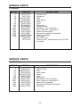
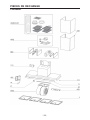
KEY NO. PART NO. DESCRIPTION
9 B08087772 Grease Filter
14 99271379 Capacitor
26 B023004301 LED
37 B02300804 Heat Sentry
73 B002090443 Glass
113 B02011550 Logo
115 BE3350233 Wiring Box
165 B03295008 Capacitor Box
485 B08016412 Decorative Flue Assembly
ARU B08092501 Duct Connector Assembly 8”
AQI B06102788 Switch Box Assembly
IME B06142997 Electrical Installation Assembly
CAS B06002309U Blower Assembly
998 B080811045 Parts Bag
- ANKCC45 Non-Ducted Kit
- AFCCC45 Charcoal filter replacement pack (4 filters
included)
SERVICE PARTS
CC45I90SB
SERVICE PARTS
CC45E90SB
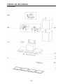
KEY NO. PART NO. DESCRIPTION
9 B08087772 Grease Filter
26 B023004301 LED
37 B02300804 Heat Sentry
73 B002090443 Glass
113 B02011550 Logo
115 BE3350233 Wiring Box
485 B08016412 Decorative Flue Assembly
ARU B08092501 Duct Connector Assembly 8”
AQI B06102789 Switch Box Assembly
IME B06142996 Electrical Installation Assembly
998 B080811045 Parts Bag
.

- 19 -
SERVICE PARTS
CC45I90SB

- 20 -
SERVICE PARTS
CC45E90SB
La page est en cours de chargement...
La page est en cours de chargement...
La page est en cours de chargement...
La page est en cours de chargement...
La page est en cours de chargement...
La page est en cours de chargement...
La page est en cours de chargement...
La page est en cours de chargement...
La page est en cours de chargement...
La page est en cours de chargement...
La page est en cours de chargement...
La page est en cours de chargement...
La page est en cours de chargement...
La page est en cours de chargement...
La page est en cours de chargement...
La page est en cours de chargement...
La page est en cours de chargement...
La page est en cours de chargement...
La page est en cours de chargement...
La page est en cours de chargement...
La page est en cours de chargement...
La page est en cours de chargement...
La page est en cours de chargement...
La page est en cours de chargement...
La page est en cours de chargement...
La page est en cours de chargement...
La page est en cours de chargement...
La page est en cours de chargement...
La page est en cours de chargement...
La page est en cours de chargement...
La page est en cours de chargement...
La page est en cours de chargement...
La page est en cours de chargement...
La page est en cours de chargement...
La page est en cours de chargement...
La page est en cours de chargement...
La page est en cours de chargement...
La page est en cours de chargement...
La page est en cours de chargement...
La page est en cours de chargement...
-
 1
1
-
 2
2
-
 3
3
-
 4
4
-
 5
5
-
 6
6
-
 7
7
-
 8
8
-
 9
9
-
 10
10
-
 11
11
-
 12
12
-
 13
13
-
 14
14
-
 15
15
-
 16
16
-
 17
17
-
 18
18
-
 19
19
-
 20
20
-
 21
21
-
 22
22
-
 23
23
-
 24
24
-
 25
25
-
 26
26
-
 27
27
-
 28
28
-
 29
29
-
 30
30
-
 31
31
-
 32
32
-
 33
33
-
 34
34
-
 35
35
-
 36
36
-
 37
37
-
 38
38
-
 39
39
-
 40
40
-
 41
41
-
 42
42
-
 43
43
-
 44
44
-
 45
45
-
 46
46
-
 47
47
-
 48
48
-
 49
49
-
 50
50
-
 51
51
-
 52
52
-
 53
53
-
 54
54
-
 55
55
-
 56
56
-
 57
57
-
 58
58
-
 59
59
-
 60
60


Best CC45E90SB Guide d'installation
- Catégorie
- Hottes
- Taper
- Guide d'installation
dans d''autres langues
- English: Best CC45E90SB Installation guide
- español: Best CC45E90SB Guía de instalación