
SSE-G3648B/BR Switch Installation Guide
Page 1
SSE-G3648B
SSE-G3648BR
Switch Installation Guide
Revision 1.0

SSE-G3648B/BR Switch Installation Guide
Page 2
The information in this Installation Manual has been carefully reviewed and is believed to be accurate. The vendor assumes no
responsibility for any inaccuracies that may be contained in this document, makes no commitment to update or to keep current the
information in this manual, or to notify any person or organization of the updates. Please Note: For the most up-to-date version of
this manual, please see our web site at www.supermicro.com.
Super Micro Computer, Inc. (“Supermicro”) reserves the right to make changes to the product described in this manual at any time
and without notice. This product, including software, if any, and documentation may not, in whole or in part, be copied, photocopied,
reproduced, translated or reduced to any medium or machine without prior written consent.
IN NO EVENT WILL SUPERMICRO BE LIABLE FOR DIRECT, INDIRECT, SPECIAL, INCIDENTAL, SPECULATIVE OR
CONSEQUENTIAL DAMAGES ARISING FROM THE USE OR INABILITY TO USE THIS PRODUCT OR DOCUMENTATION, EVEN
IF ADVISED OF THE POSSIBILITY OF SUCH DAMAGES. IN PARTICULAR, SUPERMICRO SHALL NOT HAVE LIABILITY FOR
ANY HARDWARE, SOFTWARE, OR DATA STORED OR USED WITH THE PRODUCT, INCLUDING THE COSTS OF REPAIRING,
REPLACING, INTEGRATING, INSTALLING OR RECOVERING SUCH HARDWARE, SOFTWARE, OR DATA.
Any disputes arising between manufacturer and customer shall be governed by the laws of Santa Clara County in the State of
California, USA. The State of California, County of Santa Clara shall be the exclusive venue for the resolution of any such disputes.
Super Micro's total liability for all claims will not exceed the price paid for the hardware product.
FCC Statement: This equipment has been tested and found to comply with the limits for a Class A digital device pursuant to Part 15 of
the FCC Rules. These limits are designed to provide reasonable protection against harmful interference when the equipment is
operated in a commercial environment. This equipment generates, uses, and can radiate radio frequency energy and, if not installed
and used in accordance with the manufacturer’s instruction manual, may cause harmful interference with radio communications.
Operation of this equipment in a residential area is likely to cause harmful interference, in which case you will be required to correct
the interference at your own expense.
California Best Management Practices Regulations for Perchlorate Materials: This Perchlorate warning applies only to products
containing CR (Manganese Dioxide) Lithium coin cells. Perchlorate Material-special handling may apply. See
www.dtsc.ca.gov/hazardouswaste/perchlorate for further details.
WARNING: HANDLING OF LEAD SOLDER MATERIALS USED IN THIS PRODUCT MAY EXPOSE YOU TO LEAD,
A CHEMICAL KNOWN TO THE STATE OF CALIFORNIA TO CAUSE BIRTH DEFECTS AND OTHER
REPRODUCTIVE HARM.
Manual Revision 1.0
Release Date: June 7, 2016 3:44 PM
Unless you request and receive written permission from Super Micro Computer, Inc., you may not copy any part of this document.
Information in this document is subject to change without notice. Other products and companies referred to herein are trademarks or
registered trademarks of their respective companies or mark holders.
Copyright © 2016 by Super Micro Computer, Inc.
All rights reserved.
Printed in the United States of America

SSE-G3648B/BR Switch Installation Guide
Page 3
Contents
1. Introduction .............................................................................................5
Overview ............................................................................................................. 5
Description of Hardware ..................................................................................... 6
Front Panel................................................................................................................. 6
Back Panel ................................................................................................................. 6
Status LEDs .......................................................................................................... 7
Port Description ................................................................................................... 8
Power Supply Module ....................................................................................... 10
Fan Module .......................................................................................................... 11
System Specifications........................................................................................ 11
2. Standardized Warning Statements ...................................................... 12
About Standardized Warning Statements ....................................................... 12
Warning Definition .................................................................................................. 12
Installation Instructions .......................................................................................... 15
Circuit Breaker ........................................................................................................ 16
Power Disconnection Warning .............................................................................. 17
Equipment Installation ............................................................................................ 19
Restricted Area ........................................................................................................ 20
Battery Handling ..................................................................................................... 21
Comply with Local and National Electrical Codes .............................................. 22
Product Disposal ..................................................................................................... 23
Power Cable and AC Adapter ................................................................................. 24
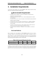
3. Installation Requirements .................................................................... 27
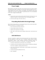
Environmental Requirements ........................................................................... 27
Dust and Particles ................................................................................................... 27
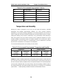
Temperature and Humidity ..................................................................................... 28
Power Supply .......................................................................................................... 29
Preventing Electrostatic Discharge Damage ....................................................... 29
Anti-interference ..................................................................................................... 29
Installation Notice .............................................................................................. 30
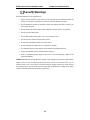
Security Warnings ............................................................................................. 31
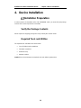
4. Device Installation ................................................................................ 32
Installation Preparation ..................................................................................... 32
Verify the Package Contents .................................................................................. 32
Required Tools and Utilities ................................................................................... 32
Device Installation ............................................................................................. 33

SSE-G3648B/BR Switch Installation Guide
Page 4
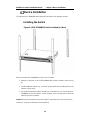
Installing the Switch ............................................................................................... 33
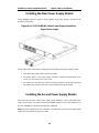
Installing the main Power Supply Module ............................................................ 34
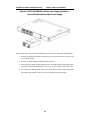
Installing the Second Power Supply Module ....................................................... 34
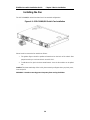
Installing the Fan ..................................................................................................... 36
Connecting the Console ......................................................................................... 37
SFP/SFP+ Transceiver Installation ........................................................................ 38
Copper Cable/Fiber Cable Connection ................................................................. 38
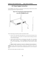
AC Power Supply Connection ............................................................................... 40
Checking the Switch ............................................................................................... 41

SSE-G3648B/BR Switch Installation Guide
Page 5
1. Introduction
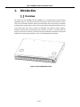
Overview
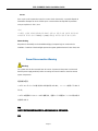
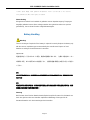
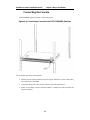
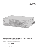
The Supermicro SSE-G3648B and SSE-G3648BR are a new generation of 1/10G Ethernet
aggregation switches. They offer 1G Ethernet connectivity for servers and end users as well as
access to 10G backbone networks and/or servers with higher speed connectivity. The available
redundant power supply option is but one of the many features making them attractive for use
in the modern data center. They are ideal as a distribution layer switch for campus networks,
enterprise networks and High Performance (HP) networks; as well as a core layer switch for
small to medium-sized networks. Preloaded with Open Networking Installation Environment
(ONIE) they are particularly suitable for use in an Open Networking environment.
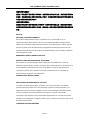
Figure 1-1 SSE-G3648B/BR Switches

SSE-G3648B/BR Switch Installation Guide
Page 6
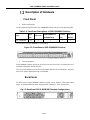
Description of Hardware
Front Panel
1. Front Panel Diagram
The front panel descriptions of the SSE-G3648B/BR switches are given in the following table:
Table 1-1: Front Panel Descriptions of SSE-G3648B/BR Switches
Type
RJ45
Port
SFP+ Port
10/100/1000Base-T
ETHERNET Port
Console
Port
USB 2.0
Interface
SSE-G3648B/BR
48
4
1
1
1
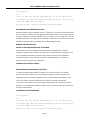
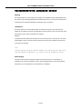
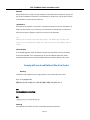
The front panel of SSE-G3648B/BR is shown below:
Figure 1-2: Front Panel of SSE-G3648B/BR Switches
2. Console description
SSE-G3648B/BR switches provide an RJ-45 serial console port. Users can perform the local
and telnet configuration through this port.
The console port supports asynchronous mode Set the data bit as 8, the stop bit as 1, the parity
bit as none, and the default baud rate as 115200bps.
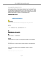
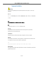
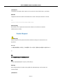
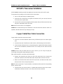
Back Panel
The back panel of SSE-G3648B/BR switches includes one 90~264VAC, 47Hz~63Hz power
supply. An optional additional power supply provides redundancy. There are three fans.
Fig 1-3: Back Panel SSE-G3648B/BR (Standard Configuration)

SSE-G3648B/BR Switch Installation Guide
Page 7
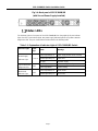
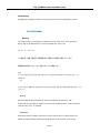
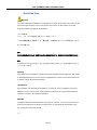
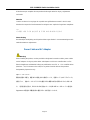
Fig 1-4: Back panel of SSE-G3648B/BR
(with Second Power Supply Installed)
Status LEDs
The indicator light on front panel of the SSE-G3648B/BR has forty-eight RJ45 port indicator
lights, four SFP+ port indicator lights, two power supply indicator lights and a system automatic
diagnostics LED. They are shown below and described in the following table.
Table 1-2: Explanation of Indicator Light of SSE-G3648B/BR Switch
Indicator Light Panel
Sign
State Meanings
Power Supply
Indicator Light
P-1 / P-2
Green light always on
Power supply module move normally
Amber light always on
Power fault
No light
No power supply
System Automatic
Diagnostic LED
STAT
Green light always on
System running normally
Green light blinks
System booting
Work Mode
Indicator Light
MAST
Green light always on
Master mode
Amber light always on
Slave mode

SSE-G3648B/BR Switch Installation Guide
Page 8
Table 1-3: Explanation of the Port Indicator Light
Indicator Light Panel Sign State
ETHERNET Port
Link Light (Right)
Green
The port is under the connection state of 10M, 100M or
1000M
Blinking Green
The port is transmitting data
No light
No connection or fail to connect
Indicator Light of
SFP+ Port
Green
The port is under the connection state of 1G/10G
Blinking Green
The port is transmitting data
No light
No connection or fail to connect
Indicator Light of
RJ45 Port
Green
The port is connected at 1G
Amber
The port is connected at of 10M/100M
Blinking Green
The 1G port is transmitting data
Blinking Amber
The 10M/100M port transmitting data
No light
No connection or fail to connect
Port Description
The SSE-G3648B/BR provide forty-eight RJ45 ports and four 10 Gb SFP+ ports.
SSE-G3648B/BR series switches support the following SFP transceivers:
• SFP-SX-L transceiver
• SFP-LX-L transceiver
• SFP-LX-20-L 20 km transceiver
• SFP-LX-40 40 km mid distance transceiver
• SFP-LH-70-L 70 km long distance transceiver
• SFP-LH-120-L 120 km long distance transceiver
• SFP-GT 1000 Base-T SFP interface cards module

SSE-G3648B/BR Switch Installation Guide
Page 9
Each port is described below:
Table 1-4: SSE-G3648B/BR Port Description
Port Mode Spec
RJ-45 port 10/100/1000Mbps auto negotiation
MDI/MDI-X cable mode auto negotiation
5 kinds of UTP: 100 m
SFP
SFP-SX-L transceiver
1000Base-SX SFP(850nm,MMF,550m)
SFP-LX-L transceiver
1000Base-LX SFP(1310nm, SMF, 10km or MMF, 550m)
SFP-LX-20-L transceiver
1310nm light wave, 9/125um single mode fiber: 20km
SFP-LX-40 transceiver
9/125um single mode fiber: 40km
SFP-LH-70-L transceiver
9/125um single mode fiber: 70km
SFP-LH-120-L transceiver
9/125um single mode fiber: 120km
SSE-G3648B/BR switches provide 4 SFP+ ports. In addition to support of optical fiber
connections through transceivers, they support SFP+ Direct Attach Copper (DAC) cables
(0.5M-7M). This provides enhanced flexibility in network design and installation.

SSE-G3648B/BR Switch Installation Guide
Page 10
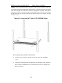
Power Supply Module
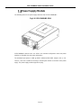
The following picture is the power supply module (PSM) of SSE-G3648B/BR.:
Fig 1-5: SSE-G3648B/BR PSM
SSE-G3648B/BR switches have one PSM in the standard configuration. When two power
supplies are installed, they give power redundancy.
The maximum input power is 200W @ 90VAC~264VAC/47HZ~63HZ. Output is 12V +/- 5%.
There is a fan and a handle for inserting or removing the module on the back of the power
supply. The power supply module supports hot plug.

SSE-G3648B/BR Switch Installation Guide
Page 11
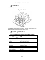
Fan Module
The SSE-G3648B/BR series fan module is shown below:
Fig 1-6: Fan Module
SSE-G3648B/BR switches have three fan modules. The rotation speed of the fan is self-
adjusting, based upon system temperature, and supports hot plug.
System Specifications
Table 1-5: System Specifications of SSE-G3648B/BR Switches
Type
Attribute
E1031
Dimension(W * H * D) (mm)
320×434×44
Weight
5.6 kg (standard: one power)
Fixed Port
48 RJ45 ports; 4 SFP+ ports
Management Port 1 RJ-45 serial console port
1 RJ-45 management Ethernet port
Power Input
90~264VAC(47~63Hz)
System Consumption
<100W
Operating Temperature
0°C~45°C
Storage Temperature
-40°C~70°C
Relative Humidity
5%~85%, no condensing

SSE-G3648B/BR Switch Installation Guide
Page 12
2. Standardized Warning Statements
About Standardized Warning
Statements
The following statements are industry standard warnings, provided to warn the user of
situations which have the potential for bodily injury. Should you have questions or experience
difficulty, contact Supermicro's Technical Support department for assistance. Only certified
technicians should attempt to install or configure components.
Read this appendix in its entirety before installing or configuring components in the
Supermicro chassis
These warnings may also be found on our web site at
http://www.supermicro.com/about/policies/safety_information.cfm
Warning Definition
Warning!
This warning symbol means danger. You are in a situation that could cause bodily injury.
Before you work on any equipment, be aware of the hazards involved with electrical circuitry
and be familiar with standard practices for preventing accidents.
警告の定義
この警告サインは危険を意味します。
人身事故につながる可能性がありますので、いずれの機器でも動作させる前に、
電気回路に含まれる危険性に注意して、標準的な事故防止策に精通して下さい。

SSE-G3648B/BR Switch Installation Guide
Page 13
此警告符号代表危险。
您正处于可能受到严重伤害的工作环境中。在您使用设备开始工作之前,必须充分意识到触电
的危险,并熟练掌握防止事故发生的标准工作程序。请根据每项警告结尾的声明号码找到此设
备的安全性警告说明的翻译文本。
此警告符號代表危險。
您正處於可能身體可能會受損傷的工作環境中。在您使用任何設備之前,請注意觸電的危險,
並且要熟悉預防事故發生的標準工作程序。請依照每一注意事項後的號碼找到相關的翻譯說明
內容。
Warnung
WICHTIGE SICHERHEITSHINWEISE
Dieses Warnsymbol bedeutet Gefahr. Sie befinden sich in einer Situation, die zu
Verletzungen führen kann. Machen Sie sich vor der Arbeit mit Geräten mit den Gefahren
elektrischer Schaltungen und den üblichen Verfahren zur Vorbeugung vor Unfällen vertraut.
Suchen Sie mit der am Ende jeder Warnung angegebenen Anweisungsnummer nach der
jeweiligen Übersetzung in den übersetzten Sicherheitshinweisen, die zusammen mit diesem
Gerät ausgeliefert wurden.
BEWAHREN SIE DIESE HINWEISE GUT AUF.
INSTRUCCIONES IMPORTANTES DE SEGURIDAD
Este símbolo de aviso indica peligro. Existe riesgo para su integridad física. Antes de
manipular cualquier equipo, considere los riesgos de la corriente eléctrica y familiarícese con
los procedimientos estándar de prevención de accidentes. Al final de cada advertencia
encontrará el número que le ayudará a encontrar el texto traducido en el apartado de
traducciones que acompaña a este dispositivo.
GUARDE ESTAS INSTRUCCIONES.
IMPORTANTES INFORMATIONS DE SÉCURITÉ
Ce symbole d'avertissement indique un danger. Vous vous trouvez dans une situation
pouvant entraîner des blessures ou des dommages corporels. Avant de travailler sur un
équipement, soyez conscient des dangers liés aux circuits électriques et familiarisez-vous
avec les procédures couramment utilisées pour éviter les accidents. Pour prendre
connaissance des traductions des avertissements figurant dans les consignes de sécurité
traduites qui accompagnent cet appareil, référez-vous au numéro de l'instruction situé à la fin
de chaque avertissement.
CONSERVEZ CES INFORMATIONS

SSE-G3648B/BR Switch Installation Guide
Page 14
안전을 위한 주의사항
경고!
이 경고 기호는 위험이 있음을 알려 줍니다. 작업자의 신체에 부상을 야기 할 수 있는 상태에 있게 됩니다.
모든 장비에 대한 작업을 수행하기 전에 전기회로와 관련된 위험요소들을 확인하시고 사전에 사고를 방지할
수 있도록 표준 작업절차를 준수해 주시기 바랍니다.
해당 번역문을 찾기 위해 각 경고의 마지막 부분에 제공된 경고문 번호를 참조하십시오
BELANGRIJKE VEILIGHEIDSINSTRUCTIES
Dit waarschuwings symbool betekent gevaar. U verkeert in een situatie die lichamelijk letsel
kan veroorzaken. Voordat u aan enige apparatuur gaat werken, dient u zich bewust te zijn van
de bij een elektrische installatie betrokken risico's en dient u op de hoogte te zijn van de
standaard procedures om ongelukken te voorkomen. Gebruik de nummers aan het eind van
elke waarschuwing om deze te herleiden naar de desbetreffende locatie.
BEWAAR DEZE INSTRUCTIES
INSTRUCCIONES IMPORTANTES DE SEGURIDAD
Este símbolo de aviso indica peligro. Existe riesgo para su integridad física. Antes de
manipular cualquier equipo, considere los riesgos de la corriente eléctrica y familiarícese con
los procedimientos estándar de prevención de accidentes. Al final de cada advertencia
encontrará el número que le ayudará a encontrar el texto traducido en el apartado de
traducciones que acompaña a este dispositivo.
GUARDE ESTAS INSTRUCCIONES.
IMPORTANTES INFORMATIONS DE SÉCURITÉ
Ce symbole d'avertissement indique un danger. Vous vous trouvez dans une situation
pouvant entraîner des blessures ou des dommages corporels. Avant de travailler sur un
équipement, soyez conscient des dangers liés aux circuits électriques et familiarisez-vous
avec les procédures couramment utilisées pour éviter les accidents. Pour prendre
connaissance des traductions des avertissements figurant dans les consignes de sécurité
traduites qui accompagnent cet appareil, référez-vous au numéro de l'instruction situé à la fin
de chaque avertissement.
CONSERVEZ CES INFORMATIONS
안전을 위한 주의사항
경고!
이 경고 기호는 위험이 있음을 알려 줍니다. 작업자의 신체에 부상을 야기 할 수 있는 상태에 있게 됩니다.
모든 장비에 대한 작업을 수행하기 전에 전기회로와 관련된 위험요소들을 확인하시고 사전에 사고를 방지할
수 있도록 표준 작업절차를 준수해 주시기 바랍니다.
해당 번역문을 찾기 위해 각 경고의 마지막 부분에 제공된 경고문 번호를 참조하십시오

SSE-G3648B/BR Switch Installation Guide
Page 15
BELANGRIJKE VEILIGHEIDSINSTRUCTIES
Dit waarschuwings symbool betekent gevaar. U verkeert in een situatie die lichamelijk letsel
kan veroorzaken. Voordat u aan enige apparatuur gaat werken, dient u zich bewust te zijn van
de bij een elektrische installatie betrokken risico's en dient u op de hoogte te zijn van de
standaard procedures om ongelukken te voorkomen. Gebruik de nummers aan het eind van
elke waarschuwing om deze te herleiden naar de desbetreffende locatie.
BEWAAR DEZE INSTRUCTIES
Installation Instructions
Warning!
Read the installation instructions before connecting the system to the power source.
設置手順書
システムを電源に接続する前に、設置手順書をお読み下さい。
警告
将此系统连接电源前,请先阅读安装说明。
警告
將系統與電源連接前,請先閱讀安裝說明。
Warnung
Vor dem Anschließen des Systems an die Stromquelle die Installationsanweisungen lesen.
¡Advertencia!
Lea las instrucciones de instalación antes de conectar el sistema a la red de alimentación.
Attention
Avant de brancher le système sur la source d'alimentation, consulter les directives
d'installation.
시스템을 전원에 연결하기 전에 설치 안내를 읽어주십시오.

SSE-G3648B/BR Switch Installation Guide
Page 16
Waarschuwing
Raadpleeg de installatie-instructies voordat u het systeem op de voedingsbron aansluit.
Circuit Breaker
Warning!
This product relies on the building's installation for short-circuit (overcurrent) protection.
Ensure that the protective device is rated not greater than: 250 V, 20 A
サーキット・ブレーカー
この製品は、短絡(過電流)保護装置がある建物での設置を前提としています。
保護装置の定格が 250 V、20 A を超えないことを確認下さい。
警告
此产品的短路(过载电流)保护由建筑物的供电系统提供,确保短路保护设备的额定电流不大于
250V,20A。
警告
此產品的短路(過載電流)保護由建築物的供電系統提供,確保短路保護設備的額定電流不大於
250V,20A。
Warnung
Dieses Produkt ist darauf angewiesen, dass im Gebäude ein Kurzschluss- bzw.
Überstromschutz installiert ist. Stellen Sie sicher, dass der Nennwert der Schutzvorrichtung
nicht mehr als: 250 V, 20 A beträgt.
¡Advertencia!
Este equipo utiliza el sistema de protección contra cortocircuitos (o sobrecorrientes) del
edificio. Asegúrese de que el dispositivo de protección no sea superior a: 250 V, 20 A.

SSE-G3648B/BR Switch Installation Guide
Page 17
Attention
Pour ce qui est de la protection contre les courts-circuits (surtension), ce produit dépend de
l'installation électrique du local. Vérifiez que le courant nominal du dispositif de protection
n'est pas supérieur à :250 V, 20 A.
경고!
이 제품은 전원의 단락(과전류)방지에 대해서 전적으로 건물의 관련 설비에 의존합니다.
보호장치의 정격이 반드시 250V(볼트), 20A(암페어)를 초과하지 않도록 해야 합니다.
Waarschuwing
Dit product is afhankelijk van de kortsluitbeveiliging (overspanning) van uw electrische
installatie. Controleer of het beveiligde aparaat niet groter gedimensioneerd is dan 220V, 20A.
Power Disconnection Warning
Warning!
The system must be disconnected from all sources of power and the power cord removed
from the power supply module(s) before accessing the chassis interior to install or remove
system components.
電源切断の警告
システムコンポーネントの取り付けまたは取り外しのために、シャーシー内部にアクセスす
るには、
システムの電源はすべてのソースから切断され、電源コードは電源モジュールから取り外す
必要があります。
警告
在你打开机箱并安装或移除内部器件前,必须将系统完全断电,并移除电源线。
警告

SSE-G3648B/BR Switch Installation Guide
Page 18
在您打開機殼安裝或移除內部元件前,必須將系統完全斷電,並移除電源線。
Warnung
Das System muss von allen Quellen der Energie und vom Netzanschlusskabel getrennt sein,
das von den Spg.Versorgungsteilmodulen entfernt wird, bevor es auf den Chassisinnenraum
zurückgreift, um Systemsbestandteile anzubringen oder zu entfernen.
¡Advertencia!
El sistema debe ser disconnected de todas las fuentes de energía y del cable eléctrico
quitado de los módulos de fuente de alimentación antes de tener acceso el interior del chasis
para instalar o para quitar componentes de sistema.
Attention
Le système doit être débranché de toutes les sources de puissance ainsi que de son cordon
d'alimentation secteur avant d'accéder à l'intérieur du chassis pour installer ou enlever des
composants de systéme.
경고!
시스템에 부품들을 장착하거나 제거하기 위해서는 섀시 내부에 접근하기 전에 반드시
전원 공급장치로부터 연결되어있는 모든 전원과 전기코드를 분리해주어야 합니다.
Waarschuwing
Voordat u toegang neemt tot het binnenwerk van de behuizing voor het installeren of
verwijderen van systeem onderdelen, dient u alle spanningsbronnen en alle stroomkabels
aangesloten op de voeding(en) van de behuizing te verwijderen.

SSE-G3648B/BR Switch Installation Guide
Page 19
Equipment Installation
Warning!
Only trained and qualified personnel should be allowed to install, replace, or service this
equipment.
機器の設置
トレーニングを受け認定された人だけがこの装置の設置、交換、またはサービスを許可され
ています。
警告
只有经过培训且具有资格的人员才能进行此设备的安装、更换和维修。
警告
只有經過受訓且具資格人員才可安裝、更換與維修此設備。
Warnung
Das Installieren, Ersetzen oder Bedienen dieser Ausrüstung sollte nur geschultem,
qualifiziertem Personal gestattet werden.
¡Advertencia!
Solamente el personal calificado debe instalar, reemplazar o utilizar este equipo.
Attention
Il est vivement recommandé de confier l'installation, le remplacement et la maintenance de
ces équipements à des personnels qualifiés et expérimentés.
경고!
훈련을 받고 공인된 기술자만이 이 장비의 설치, 교체 또는 서비스를 수행할 수 있습니다.
Waarschuwing
Deze apparatuur mag alleen worden geïnstalleerd, vervangen of hersteld door geschoold en
gekwalificeerd personeel.

SSE-G3648B/BR Switch Installation Guide
Page 20
Restricted Area
Warning!
This unit is intended for installation in restricted access areas. A restricted access area can be
accessed only through the use of a special tool, lock and key, or other means of security.
(This warning does not apply to workstations).
アクセス制限区域
このユニットは、アクセス制限区域に設置されることを想定しています。
アクセス制限区域は、特別なツール、鍵と錠前、その他のセキュリティの手段を用いてのみ
出入りが可能です。
警告
此部件应安装在限制进出的场所,限制进出的场所指只能通过使用特殊工具、锁和钥匙或其它安全手段进出的场所。
警告
此裝置僅限安裝於進出管制區域,進出管制區域係指僅能以特殊工具、鎖頭及鑰匙或其他安全
方式才能進入的區域。
Warnung
Diese Einheit ist zur Installation in Bereichen mit beschränktem Zutritt vorgesehen. Der Zutritt
zu derartigen Bereichen ist nur mit einem Spezialwerkzeug, Schloss und Schlüssel oder einer
sonstigen Sicherheitsvorkehrung möglich.
¡Advertencia!
Esta unidad ha sido diseñada para instalación en áreas de acceso restringido. Sólo puede
obtenerse acceso a una de estas áreas mediante la utilización de una herramienta especial,
cerradura con llave u otro medio de seguridad.
Attention
Cet appareil doit être installée dans des zones d'accès réservés. L'accès à une zone d'accès
réservé n'est possible qu'en utilisant un outil spécial, un mécanisme de verrouillage et une
clé, ou tout autre moyen de sécurité.
경고!
La page charge ...
La page charge ...
La page charge ...
La page charge ...
La page charge ...
La page charge ...
La page charge ...
La page charge ...
La page charge ...
La page charge ...
La page charge ...
La page charge ...
La page charge ...
La page charge ...
La page charge ...
La page charge ...
La page charge ...
La page charge ...
La page charge ...
La page charge ...
La page charge ...
-
 1
1
-
 2
2
-
 3
3
-
 4
4
-
 5
5
-
 6
6
-
 7
7
-
 8
8
-
 9
9
-
 10
10
-
 11
11
-
 12
12
-
 13
13
-
 14
14
-
 15
15
-
 16
16
-
 17
17
-
 18
18
-
 19
19
-
 20
20
-
 21
21
-
 22
22
-
 23
23
-
 24
24
-
 25
25
-
 26
26
-
 27
27
-
 28
28
-
 29
29
-
 30
30
-
 31
31
-
 32
32
-
 33
33
-
 34
34
-
 35
35
-
 36
36
-
 37
37
-
 38
38
-
 39
39
-
 40
40
-
 41
41


Supermicro SSE-G3648B Guide d'installation
- Taper
- Guide d'installation
- Ce manuel convient également à
dans d''autres langues
Documents connexes
Autres documents
-
 FS Managed L2+ Gigabit Switches Mode d'emploi
-
Add-On Computer Peripherals (ACP) GLC-FE-100LX-RGD-AO Fiche technique
-
SUPER MICRO Computer SBA-7142G-T4 Manuel utilisateur
-
LG-Ericsson ipecs ES-5048XG Guide d'installation
-
Leonton RPG5-2602-2C Manuel utilisateur
-
red lion NT24k Series Manuel utilisateur
-
SMC Networks SMC8028L2 Manuel utilisateur
-
Brocade Communications Systems 53-1002580-01 Manuel utilisateur
-
-
Korenix JetNet 5828G Series Quick Installation Manual
