
USER’S MANUAL
Revision 1.0
SCE102

2
SCE102 Chassis User's Manual
The information in this User’s Manual has been carefully reviewed and is believed to be accurate. The vendor assumes
no responsibility for any inaccuracies that may be contained in this document, and makes no commitment to update
or to keep current the information in this manual, or to notify any person or organization of the updates. Please Note:
For the most up-to-date version of this manual, please see our website at www.supermicro.com.
Super Micro Computer, Inc. ("Supermicro") reserves the right to make changes to the product described in this manual
at any time and without notice. This product, including software and documentation, is the property of Supermicro and/
or its licensors, and is supplied only under a license. Any use or reproduction of this product is not allowed, except
as expressly permitted by the terms of said license.
IN NO EVENT WILL Super Micro Computer, Inc. BE LIABLE FOR DIRECT, INDIRECT, SPECIAL, INCIDENTAL,
SPECULATIVE OR CONSEQUENTIAL DAMAGES ARISING FROM THE USE OR INABILITY TO USE THIS PRODUCT
OR DOCUMENTATION, EVEN IF ADVISED OF THE POSSIBILITY OF SUCH DAMAGES. IN PARTICULAR, SUPER
MICRO COMPUTER, INC. SHALL NOT HAVE LIABILITY FOR ANY HARDWARE, SOFTWARE, OR DATA STORED
OR USED WITH THE PRODUCT, INCLUDING THE COSTS OF REPAIRING, REPLACING, INTEGRATING,
INSTALLING OR RECOVERING SUCH HARDWARE, SOFTWARE, OR DATA.
Any disputes arising between manufacturer and customer shall be governed by the laws of Santa Clara County in the
State of California, USA. The State of California, County of Santa Clara shall be the exclusive venue for the resolution
of any such disputes. Supermicro's total liability for all claims will not exceed the price paid for the hardware product.
FCC Statement: This equipment has been tested and found to comply with the limits for a Class B digital device
pursuant to Part 15 of the FCC Rules. These limits are designed to provide reasonable protection against harmful
interference when the equipment is operated in a commercial environment. This equipment generates, uses, and can
radiate radio frequency energy and, if not installed and used in accordance with the manufacturer’s instruction manual,
may cause harmful interference with radio communications. Operation of this equipment in a residential area is likely
to cause harmful interference, in which case you will be required to correct the interference at your own expense.
California Best Management Practices Regulations for Perchlorate Materials: This Perchlorate warning applies only
to products containing CR (Manganese Dioxide) Lithium coin cells. “Perchlorate Material-special handling may apply.
See www.dtsc.ca.gov/hazardouswaste/perchlorate”.
The products sold by Supermicro are not intended for and will not be used in life support systems, medical equipment,
nuclear facilities or systems, aircraft, aircraft devices, aircraft/emergency communication devices or other critical
property damage. Accordingly, Supermicro disclaims any and all liability, and should buyer use or sell such products
for use in such ultra-hazardous applications, it does so entirely at its own risk. Furthermore, buyer agrees to fully
indemnify, defend and hold Supermicro harmless for and against any and all claims, demands, actions, litigation, and
proceedings of any kind arising out of or related to such ultra-hazardous use or sale.
Manual Revision 1.0
Release Date: December 10, 2018
Unless you request and receive written permission from Super Micro Computer, Inc., you may not copy any part of this
to herein are trademarks or registered trademarks of their respective companies or mark holders.
Copyright © 2018 by Super Micro Computer, Inc.
All rights reserved.
Printed in the United States of America
WARNING: This product can expose you to chemicals including
lead, known to the State of California to cause cancer and birth
defects or other reproductive harm. For more information, go
to www.P65Warnings.ca.gov.
!

3
Preface
3
Preface
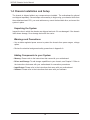
About this Manual
This manual is written for professional system integrators and PC technicians. It provides
information for the installation and use of the Supermicro SCE102.chassis. Installation and
maintenance should be performed by experienced technicians only.
hardware (http://www.supermicro.com).
Notes
For your system to work properly, please follow the links below to download all necessary
drivers/utilities and the user’s manual for your server.
• Supermicro product manuals: https://www.supermicro.com/support/manuals/
• Product drivers and utilities: https://www.supermicro.com/support/resources/
• Product safety info: https://www.supermicro.com/about/policies/safety_information.cfm
If you have any questions, please contact our support team at:
This manual may be periodically updated without notice. Please check the Supermicro website
for possible updates to the manual revision level.
Warnings
Special attention should be given to the following symbols used in this manual.
Warning! Indicates high voltage may be encountered when performing a procedure.
Warning! Indicates important information given to prevent equipment/property damage

4
SCE102 Chassis User's Manual
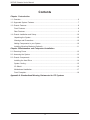
Contents
Chapter 1 Introduction
1.1 Overview ...............................................................................................................................6
1.2 Supported System Features.................................................................................................7
1.3 Chassis Features .................................................................................................................8
Front Features .....................................................................................................................8
Rear Features .....................................................................................................................9
1.4 Chassis Installation and Setup ...........................................................................................10
Unpacking the System ......................................................................................................10
Warnings and Precautions ................................................................................................10
Adding Components to your System ...............................................................................10
Installing Mounting Brackets (Optional) ............................................................................11
Chapter 2 Maintenance and Component Installation
2.1 Removing Power ................................................................................................................12
2.2 Accessing the System ........................................................................................................13
2.3 Chassis Components .........................................................................................................14
Installing the Hard Drive ..................................................................................................14
System Cooling .................................................................................................................15
I/O Shield ..........................................................................................................................16
Motherboard Installation ....................................................................................................17
Front Faceplate .................................................................................................................18
Appendix A Standardized Warning Statements for DC Systems

5
Contacting Supermicro
5
Contacting Supermicro
Headquarters
Address: Super Micro Computer, Inc.
980 Rock Ave.
San Jose, CA 95131 U.S.A.
Tel: +1 (408) 503-8000
Fax: +1 (408) 503-8008
Email: [email protected] (General Information)
[email protected] (Technical Support)
Website: www.supermicro.com
Europe
Address: Super Micro Computer B.V.
Het Sterrenbeeld 28, 5215 ML
's-Hertogenbosch, The Netherlands
Tel: +31 (0) 73-6400390
Fax: +31 (0) 73-6416525
Email: [email protected] (General Information)
[email protected] (Technical Support)
[email protected] (Customer Support)
Website: www.supermicro.nl
Asia-Pacic
Address: Super Micro Computer, Inc.
3F, No. 150, Jian 1st Rd.
Zhonghe Dist., New Taipei City 235
Taiwan (R.O.C)
Tel: +886-(2) 8226-3990
Fax: +886-(2) 8226-3992
Email: [email protected]
Website: www.supermicro.com.tw

6
SCE102 Chassis User's Manual
Main Parts List
Description Part Number
AC to DC 40W lockable power adapter MCP-250-10124-0N
AC to DC 60W lockable power adapter MCP-250-10117-0N
Serial Cable, 2x DB9M TO 2X10F/P2.00,INT TO EXT,FLAT, 12CM CBL-CUSB-1045
SATA POWER Cable, 25CM CBL-PWEX-0982
SATA Cable, 25cm CBL-SAST-0881
Front Panel Mylar with 4x COM port opening only MCP-160-10202-0B
Front Panel Mylar with 4x COM port and Audio port MCP-160-10203-0B
Front Panel Mylar with Audio port only MCP-160-10204-0B
I/O shield for X11SSN MCP-260-10202-0B
I/O shield for A2SAN and X11SAN MCP-260-10201-0B
Wall mount / VESA mount MCP-290-10113-0B
Chapter 1
Introduction
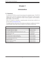
1.1 Overview
The Supermicro SCE102 is a compact chassis designed for embedded systems. The SCE102
motherboards. Some of its potential uses include a security appliance, video surveillance,
digital signage, or an indoor kiosk.
with the system (www.supermicro.com).
This chapter provides a brief outline of the functions and features. In addition to the chassis,
several important optional parts that are available for the chassis are listed below.

7
Chapter 1: Introduction
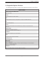
1.2 Supported System Features
The following table provides an overview of the supported main features of the SCE102.
System Features
Supported Supermicro Motherboards
A2SAN and X11SSN
Chassis
Compact Embedded Pico ITX Box, SCE102
CPU
Intel Atom E3930 Dual Core SoC, 6.5W (System on a Chip) in the FCBGA 1296 format.
Fan
One 4-cm PWM system fan,
Memory
Supports up to 8 GB of DDR3L Non-ECC SO-DIMM memory at 1866 MHz in one horizontal socket
One M.2 slot
Expansion Slots
One Mini PCI-E (SATA/PCIex1/USB 2.0)
One M.2 B Key 2242/2280 (SATA/PCIex2/USB 2.0)
Hard Drives
Power
One external 40 watt 12VDC power adapter
Input/Output Ports
LAN: Dual Gigabit ports
HDMI: One port
VGA: One port
USB: Two USB3.0 ports
Display: one DisplayPort, one HDMI, one VGA (two independent displays), one Intel HD Graphics
Serial ATA: Two SATA3 (6Gbps) ports
COM ports: (Four front, optional)
Dimensions
Width 7.48" (190mm), Height 1.72" (43.6mm), Depth 4.72" (120mm)

8
SCE102 Chassis User's Manual
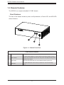
Front Chassis Features
Item Feature Description
1 Power button
The power switch applies or removes power to the server system. Turning
supplied to the system.
2 Power LED When the blue Power LED is on, this indicates that the system is on.
3 HDD LED
drives.
Figure 1-1. Chassis Front View
1.3 Chassis Features
The SCE102 is a compact embedded 3.5" SBC chassis.
Front Features
status indicators.
1
2
3

9
Chapter 1: Introduction
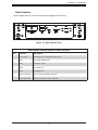
Rear Features
Shown below are rear cut-out holes for the supported I/O devices
Figure 1-2. Rear Chassis View
Rear Chassis Features (Back I/O Panel Cut-outs)
Item Features Description
1 Power Input Use this port for the 40W DC power input.
2 LAN Two 1GbE network ports
3 USB USB 3.0/3.1 ports
4 HDMI One HDMI port
5 VGA VGA Video port
6 Antenna Cut-outs Two cut-outs for mounting antennas
7 Kensington® Slot Slot for Kensington security cable/lock
6
3
1
4 5
2
6
7

10
SCE102 Chassis User's Manual
1.4 Chassis Installation and Setup
The chassis is shipped without any components pre installed. The motherboard is optional
and shipped separately. Several steps are necessary to begin using your chassis. Aside from
the motherboard and CPU, you must add memory, mount the hard disk drive, and mount the
system in place.
Unpacking the System
Inspect the box in which the chassis was shipped and note if it was damaged. If the chassis
Warnings and Precautions
• Use a stable regulated power source to protect the chassis from power surges, voltage
spikes.
• Review the electrical and general safety precautions in Appendix A.
Adding Components to your System
• Memory: Please refer to the instructions that came with your motherboard.
• Drives and Storage: To add storage capabilities to your chassis, see Chapter 2. Refer to
the instructions that came with your motherboard for connection procedures.
• Input/Output: Please refer to the instructions that came with your motherboard.
• Software: Please refer to the instructions that came with your software.

11
Chapter 1: Introduction
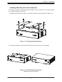
Installing Mounting Brackets (Optional)
The chassis includes mounting brackets that allow it to be mounted in a convenient place.
Use of these brackets is optional.
1. Installed the brackets using the four provided screws as shown below (as Figure 1-5).
Figure 1-3. Installing Mounting Brackets
2. Secure the brackets to the surface where you want the server to be mounted.
Figure 1-4. Installed Mounting Brackets
(Brackets under the chassis)

12
SCE102 Chassis User's Manual
Chapter 2
Maintenance and Component Installation
This chapter provides instructions on installing and replacing main system components. To
numbers given.
system. Please follow the procedures given in each section.
2.1 Removing Power
Use the following procedure to ensure that power has been removed from the system. This
step is necessary when removing or installing non hot-swap components or when replacing
a non-redundant power supply.
1. Use the operating system to power down the system.
2. After the system has completely shut-down, disconnect the AC power cord from the
power source.
3. Disconnect the power cord from the chassis.

13
Chapter 2: Maintenance and Component Installation
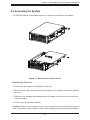
2.2 Accessing the System
The SCE102 features a removable top cover to access to the inside of the chassis.
Removing the Top Cover
1. Power down the system as described in section 2.1.
2. Remove the two side screws that hold the chassis cover in place and set these aside for
later use.
3. Slide the cover sideways as illlustrated above to release the front and rear cover hooks
from the chassis.
4.
Caution: Except for short periods of time, do not operate the server without the cover in
.
Figure 2-1. Removing the Chassis Cover
2
3
2

14
SCE102 Chassis User's Manual
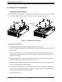
Installing the Hard Drive
The motherboard should be installed before installing the hard drive.
1. Make sure there is no power to the system as described in section 2.1 and remove the
chassis cover.
2. Remove the four screws securing the bottom cover tray to the chassis and set them
aside for later use. Lift the cover out. On the inside of this bottom cover is where the
hard drive is mounted.
3. Place the hard drive on to the inside of the bottom cover and secure it to the tray with
the four screws provided with the hard drive, as shown.
4. Attach the cable SATA connector and to the motherboard connector. This cable carries
both the SATA signal and the SATA power.
5. Return the hard drive bottom cover assembly into the chassis, aligning the screw holes
of the bottom tray with the holes in the chassis. Secure the tray to the chassis support
bracket with the screws previously set aside.
6. Power up the system.
2.3 Chassis Components
Installing the Hard Drive
to the inside of the bottom cover of the chassis. Use an enterprise quality drive.
Figure 2-2. Installing the Hard Drive
3
2
Hard Drive

15
Chapter 2: Maintenance and Component Installation
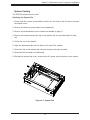
System Cooling
The SCE102 includes one 4-cm fan.
Replacing the System Fan
1. Power down the system as described in section 2.1 and remove the AC power cord and
the chassis cover.
2. Remove the failed fan power cable from motherboard.
3. Remove the motherboard from the chassis as detailed on page 17.
4. Remove the screws securing the fan to the chassis wall and set these aside for later
use.
5. Lift the fan out of the chassis.
6. Align the replacement fan with the holes in the wall of the chassis.
7. Secure the fan to the chassis wall using the screws previously set aside.
8. Reconnect the fan cable to motherboard.
9. Reinstall the chassis top cover, reconnect the AC power cord and power up the system.
Figure 2-3. System Fan

16
SCE102 Chassis User's Manual
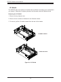
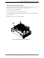
I/O Shield
Removing the I/O Shield
1. Remove the top chassis cover.
2. Remove the two screws as indicated on the illustration below.
3. To remove, pull the I/O shield outward from the rear of the chassis.
Figure 2-4. I/O Shield
X11SSN I/O Shield
A2SAN I/O Shield

17
Chapter 2: Maintenance and Component Installation
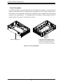
Motherboard Installation/Removal
The SCE102 supports the Supermicro A2SAN and X11SSN motherboard family. The
installation procedure is the same regardless of motherboard model.
To install or remove the motherboard
1. Remove the top chassis cover as explained on page 13.
2. Align the motherboard with the screw holes directly on the chassis and secure with the
screws provided.
3. Reverse this process to remove the motherboard.
2
Figure 2-5. Motherboard Installation/Removal

18
SCE102 Chassis User's Manual
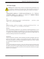
Front Faceplate
chassis cutout holes to mount I/O devices such as serial ports, etc, but other models will not.
simply pressed to the front of the chassis to secure.
The Mylar front faceplate may be
replaced with one that has cutouts
-
tions, such as these for serial ports
Mylar front faceplate
Figure 2-6. Front Faceplate

19
SCE102 Chassis User's Manual
Appendix A
Standardized Warning Statements for DC
Systems
A.1 About Standardized Warning Statements
The following statements are industry standard warnings, provided to warn the user of
situations which have the potential for bodily injury. Should you have questions or experience
chassis.
These warnings may also be found on our website at http://www.supermicro.com/about/
policies/safety_information.cfm.
Warning Denition
警告の定義
この警 告サインは危 険を意 味します。
人身事故につながる可能性がありますので、いずれの機器でも動作させる前に、
電気回路に含まれる危険性に注意して、標準的な事故防止策に精通して下さい。
此警告符号代表危险。
您正处于可能受到严重伤害的工作环境中。在您使用设备开始工作之前,必须充分意识到触电
的危险,并熟练掌握防止事故发生的标准工作程序。请根据每项警告结尾的声明号码找到此设
备的安全性警告说明的翻译文本。
此警告符號代表危險。
您目前所處的工作環境可能讓您受傷。在您使用任何設備之前,請注意觸電的危險,並且要熟
悉預防事故發生的標準工作程序。請依照每一注意事項後的號碼找到相關的翻譯說明內容。
Warning! This warning symbol means danger. You are in a situation that could cause
bodily injury. Before you work on any equipment, be aware of the hazards involved
with electrical circuitry and be familiar with standard practices for preventing accidents.

20
Appendix B: Standardized Warning Statements
Warnung
WICHTIGE SICHERHEITSHINWEISE
führen kann. Machen Sie sich vor der Arbeit mit Geräten mit den Gefahren elektrischer
Sie mit der am Ende jeder Warnung angegebenen Anweisungsnummer nach der jeweiligen
Übersetzung in den übersetzten Sicherheitshinweisen, die zusammen mit diesem Gerät
ausgeliefert wurden.
BEWAHREN SIE DIESE HINWEISE GUT AUF.
Este símbolo de aviso indica peligro. Existe riesgo para su integridad física. Antes de
manipular cualquier equipo, considere los riesgos de la corriente eléctrica y familiarícese
encontrará el número que le ayudará a encontrar el texto traducido en el apartado de
traducciones que acompaña a este dispositivo.
entraîner des blessures ou des dommages corporels. Avant de travailler sur un équipement,
soyez conscient des dangers liés aux circuits électriques et familiarisez-vous avec les
avertissement.
הרהזא תורהצה ןונקת
ינפמ שמתשמה תא ריהזהל תנמ לע ,היישעתה ינקת יפ לע תורהזא ןה תואבה תורהצה
הלבח
םע רשק רוציל שי ,יהשלכ היעבב תולקתיה וא תולאש שיו הדימב .תירשפא תיזיפ
הכימת תקלחמ
.םיביכרה תא רידגהל וא ןיקתהל םיאשר דבלב םיכמסומ םיאנכט .ורקימרפוס לש תינכט
.ורקימרפוס יזראמב םיביכרה תרדגה וא תנקתה ינפל ואולמב חפסנה תא אורקל שי
La page charge ...
La page charge ...
La page charge ...
La page charge ...
La page charge ...
La page charge ...
La page charge ...
La page charge ...
La page charge ...
La page charge ...
La page charge ...
La page charge ...
La page charge ...
La page charge ...
La page charge ...
La page charge ...
La page charge ...
La page charge ...
La page charge ...
La page charge ...
-
 1
1
-
 2
2
-
 3
3
-
 4
4
-
 5
5
-
 6
6
-
 7
7
-
 8
8
-
 9
9
-
 10
10
-
 11
11
-
 12
12
-
 13
13
-
 14
14
-
 15
15
-
 16
16
-
 17
17
-
 18
18
-
 19
19
-
 20
20
-
 21
21
-
 22
22
-
 23
23
-
 24
24
-
 25
25
-
 26
26
-
 27
27
-
 28
28
-
 29
29
-
 30
30
-
 31
31
-
 32
32
-
 33
33
-
 34
34
-
 35
35
-
 36
36
-
 37
37
-
 38
38
-
 39
39
-
 40
40


dans d''autres langues
- English: Supermicro SCE102 User manual
Documents connexes
Autres documents
-
SUPER MICRO Computer SBA-7142G-T4 Manuel utilisateur
-
NEC SX-Aurora TSUBASA A300-2 Manuel utilisateur
-
Siemens MCP 1500 SINUMERIK ONE Manuel utilisateur
-
ASROCK N68PV-GS Le manuel du propriétaire
-
ASROCK K8NF4G-SATA2 Le manuel du propriétaire
-
ASROCK 939NF4G-SATA2 Le manuel du propriétaire
-
ASROCK ALIVENF7G-FULLHD Le manuel du propriétaire
-
ASROCK ALIVENF7G-HD720P R2.0 Le manuel du propriétaire
-
ASROCK K8NF4G-VSTA Le manuel du propriétaire