


3
KÜSCHALL ULTRA-LIGHT
© Küschall AG, Switzerland | 2014-07
Service Manual
TABLE OF CONTENTS
GENERAL ...................................................................................................................... 4
Introduction 4
Spare parts and adaptations 4
Fastening with hexagon socket bolts 4
Torque 5
Checks 5
Identifying and repairing faults 5
FRAME ............................................................................................................................6
Rear frame 7
Front frame 7
Retaining lever 7
SEAT .............................................................................................................................. 8
Seat height front (SHv) 8
Seat height rear (SHh) 9
Seat width (SB) 9
Seat depth (ST) 9
BACKREST ...................................................................................................................11
Backrest height 11
Adjustable-angle backrest 12
Replacing push handles / push handles and backrest 14
Replacing foldable push handles 16
FOOTRESTS ................................................................................................................19
One-piece footrest 19
Two-piece footrest 21
Two-piece footrest, adjustable-angle 21
SIDEPARTS ................................................................................................................. 22
Clothes guard/mudguard 22
Siderests 23
FRONT WHEELS ........................................................................................................ 27
Castor fork 27
Special housing guides 28
REAR WHEELS ........................................................................................................... 29
Adjusting the seat height rear 29
Tipping stability 29
Wheel camber 30
Adapter plate for drum brake 30
Distance sleeves for rear wheels 30
Fitting the hub brake 31
Adjusting the removable axle 32
BRAKES ....................................................................................................................... 33
Parking brakes 33
Drum brake 34
OPTIONS & ACCESSORIES ...................................................................................... 35
Antitipper 35
Tipper aid 36
Cane holder 36
Transit wheels 37
Fitting the pelvic belt 37
Attaching the snap hook symbols 38

4
KÜSCHALL ULTRA-LIGHT
© Küschall AG, Switzerland | 2014-07
Service Manual
GENERAL
Introduction
This Service Manual is part of the instructions and contains all the
technical information necessary for the inspection, configuration or
repair of a küschall® wheelchair.
WARNING!
Danger of accident and severe injuries.
If the wheelchair is improperly set it can cause
accidents and severe injuries.
▸Changes to the wheelchair may only be carried out
by the dealer.
To maintain the necessary levels of safety and reliability, every wheel-
chair must be thoroughly examined once a year.
Some aspects of the assembly and configuration of the wheelchair
require a high level of expertise. These assembly instructions there-
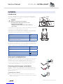
fore break the various tasks down into three categories:
Requirement Symbol
Easy – technical understanding required
Medium – technical knowledge required
Dicult – technical knowledge and expertise in
assembling wheelchairs required
The required tools and their sizes are listed before the instructions.
The various torque values with which the nuts are to be tightened are
also specified in the instructions. A torque spanner must be used, in
order to comply with the specified torque values.
Tool Symbol
Allen key à 3, 4, 5
Torx wrench ß 10
Phillips head screwdriver Ò
Open-end spanner 8, 9, 10, 18
Socket spanner/Box spanner 8, 10, 19, 22
Spare parts and adaptations
All spare parts may be obtained from the küschall® customer service
department. An electronic spare parts catalogue can be found at
www.kuschall.com. Only original spare parts may be used.
The written authorisation of Küschall AG must be obtained before
installing additional adaptations on a küschall® wheelchair.
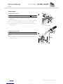
Fastening with hexagon socket bolts
Hexagon socket bolts are not designed to withstand an excessive
application of force. When tightening or undoing a hexagon socket
bolt, force must be applied to the nut wherever possible to avoid
damaging the bolt.
Tightening and undoing
Turn the nut using a socket spanner (only use an open-end
spanner if there is insucient space), using the Allen key simply to
stop the bolt turning.

5
KÜSCHALL ULTRA-LIGHT
© Küschall AG, Switzerland | 2014-07
Service Manual
Tightening and undoing when no nut is present
If a hexagon socket bolt is screwed directly into a thread, the bolt must be tightened using
the Allen key.
i Ensure that the Allen key is of good quality
and not worn.
Torque
All bolts must be tightened with the torque specified in the following instructions.
Checks
Visual check
Check the entire frame for cracks, especially the areas around joints and welded
seams.
Checking the screw connections
Check all bolts with the torques specified in the instructions regularly, and adjust if
required.
CAUTION!
Several screw connections have been secured with safety seals. If these are opened,
they must be secured again using new safety seals.
High-power and low power adhesives are available. For torque entries notice shall be
made whether an adhesive and which adhesive needs to be used.
Identifying and repairing faults
Fault Possible cause Action
The wheelchair does not
travel in a straight line
Incorrect tyre pressure on one rear wheel Correct tyre pressure
One or more spokes broken Replace broken spoke(s)
Spokes tightened unevenly Tighten loose spokes
Front wheel bearings are dirty or damaged Clean or replace the bearings
Support bearings in forks faulty Replace the support bearings
Steering error or trail angle, left and right, uneven Adjust steering error or trail angle
The wheelchair tips too
easily
Rear wheels are mounted too far forwards Mount the rear wheels further back
Backrest angle too large Reduce backrest angle
Seat angle too large Mount the adapter plate lower on the side
profile
The brakes are gripping
poorly or asymmetrically
Incorrect tyre pressure in one or both rear tyres Correct tyre pressure
Brake setting incorrect Correct brake setting
The rolling resistance is
very high
Tyre pressure in rear tyres is too low Correct tyre pressure
Rear wheels not parallel Make rear wheels parallel
Drum brake set too narrow Set the drum brake
Bearings are dirty or faulty Replace the bearings
The front wheels wobble
when moving fast
Too little tension on the clevis pin housing Tighten the nut on the castor fork slightly
Front wheel has worn smooth Replace front wheel
The front wheel is sti or
stuck Bearings are dirty or faulty Replace the bearings
The wheelchair is very
dicult to unfold The backrest cover is too tight Loosen the topmost Velcro band of the
backrest cover a little
Left and right side of the
wheelchair can be moved
in parallel to one another
Longitudinal stopping bolts on the seat edge are
loose
Tighten the longitudinal stopping bolts on
the seat edge

6
KÜSCHALL ULTRA-LIGHT
© Küschall AG, Switzerland | 2014-07
Service Manual
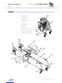
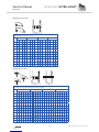
FRAME
FRAME
4
1
2
3
7
8
5
6
5
6
1
2
3
4
2
4a
4a
1a
1a
2a 1b
1b
4b
4b
7
2b
2c
8
4c
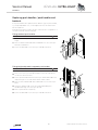
Rear frame
a à 13 Nm
b à 7 Nm
Retaining lever
a à 4 Nm
Cross
Front frame
a à 13 Nm
b à 7 Nm
c à 7 Nm
Upper connecting tube
Lower connecting tube
Seat locking mechanism
Longitudinal stopping bolts

7
KÜSCHALL ULTRA-LIGHT
© Küschall AG, Switzerland | 2014-07
Service Manual
FRAME
Rear frame
Replacing the rear frame
Diculty: Tool: Ã 5 10
Remove backrest.
Loosen and remove bolts a and b.
Pull out rear frame to the back.
Push the rear frame onto the upper and lower connecting
tubes.
Reinsert and tighten bolts a and b.
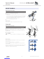
Front frame
Replacing the front frame
Diculty: Tool: Ã 3, 4, 5 10
Disassemble brakes.
Loosen and remove bolts a and b on both sides. If a flip to back
side rest is fitted, also loosen c.
Pull out front frame to the front.
Remove seat locking mechanism with threaded insert from old
front frame and fit it on the new front frame,
Chap. Seat, Turning the seat locking mechanism.
Push the front frame onto the upper and lower connecting tube.
Reinsert and tighten bolts a, b (if required c) on both sides.
Set the castor fork angle,
Chap. Front wheels, Setting the steering error angle.
Retaining lever
Replacing the retaining lever
Diculty: Tool: Ã 3, 4, 5 10
With mudguard or clothes guard, fixed: remove a and b, with
mudguard or side rest, insertable and siderest, foldable: remove a
and b.
Remove bolt a.
Pull the retaining lever from the upper connecting tube .
Remove sleeve b.
Push the new retaining lever over the upper connecting tube .
Position sleeve b with wide edge in joint c.
Secure retaining lever with bolt a.
With mudguard or clothes guard, fixed: reinsert and tighten bolts a
and b, with mudguard or side rest, insertable and side rest, flip to
back: reinsert and tighten bolts a and b.

8
KÜSCHALL ULTRA-LIGHT
© Küschall AG, Switzerland | 2014-07
Service Manual
SEAT
SEAT
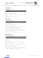
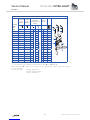
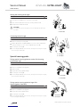
Seat height front (SHv)
Options for changing the SHv:
• Replace front wheel with larger or smaller one or fit it at another
position on the castor wheel,
Chap. Front wheels, Replacing the front wheel.
• Replace castor fork with a larger or a smaller one,
Chap. Front wheels, Replacing the castor fork.
• Fit it high/low with the housing guide Hemi,
Chap. Front wheels, Special housing guides.
Seat height front with respect to fork size, castor fork size and position in the fork
SHv [mm]
Castor fork [inch]
410 3''
420 3''
430/440 4'' 3''
450 4'' 3''
460 5'' 4'' 3''
470 5'' 4'' 3''
480/490 6'' *5'' 4'' 3''
500 6'' *5'' 4'' 3''
510 7'' *6'' *5'' 4''
520 7'' *6'' *5''
530/540 7'' *6'' *
(Assumption: Seat depth = 400 mm, seat angle = 50 mm)
fitted high: SHv - 30 mm
fitted low: SHv + 30 mm
* 6’’ and 7’’ front wheels cannot be used on the Ultra-Light dynamic frame (80°), if a
2-part angled footrest is fitted.

9
KÜSCHALL ULTRA-LIGHT
© Küschall AG, Switzerland | 2014-07
Service Manual
SEAT
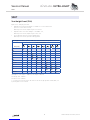
Seat height rear (SHh)
Options for changing the SHh:
• Replace rear wheel with a larger or a smaller one
• Change the position of the adapter plate
Chap. Rear wheels, Adjusting the seat height rear.
Seat height rear with respect to the rear wheels and positioning on the frame
SHh [mm]
Rear wheel size [inch]
22’’ 24’’ 25’’ 26’’
370 1
380 2
390 3 1
400/410 4 2 1
420 5 3 2 1
430 6 4 3 2
440 7 5 4 3
450/460 8 6 5 4
470 9 7 6 5
480 10 8 7 6
490 9 8 7
500 10 9 8
1
2
3
4
5
6
7
8
9
10
11
12
Seat width (SB)
SBs range from 280 - 500 mm.
Once the SB is specified, it is very dicult to change it: the cross
struts, backrest cover (on standard backs) and, on some configura-
tions, the footrests must be replaced.
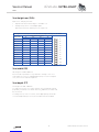
Seat depth (ST)
STs range from 320 - 500 mm.
To reduce the ST, the cross struts must be shortened and a new ap-
propriately sized seat cover fitted. At an ST ≥ 400 mm, the frame can
be shortened.
To enlarge the ST, new cross struts, a new appropriately sized seat
cover and, depending on the ST, a new frame must be installed.

10
KÜSCHALL ULTRA-LIGHT
© Küschall AG, Switzerland | 2014-07
Service Manual
SEAT
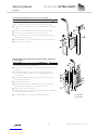
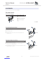
Replacing the seat cover
Diculty: Tool: ß 10
1 Loosen bolts and remove plug .
2 Remove seat cover including plastic rods.
Position new seat cover. Adjust seat cover to width SB + 25 mm.
Retighten bolts and plug .
Turning the seat locking mechanism
If the seat edge can be too easily removed from the seat locking
mechanisms, either the front two or all four seat locking mechanisms
can be rotated by 180°:
Diculty: Tool: Ã 3
Loosen bolt in seat locking mechanism.
Turn seat locking mechanism by 180°.
Secure bolt with adhesive (low-strength).
Retighten the bolt.
i Screw out the bolt only to the extent that the seat locking
mechanism can be turned as otherwise the threaded insert can
move and is then dicult to re-position.
12
1
à 4 Nm
à 4 Nm

11
KÜSCHALL ULTRA-LIGHT
© Küschall AG, Switzerland | 2014-07
Service Manual
BACKREST
BACKREST
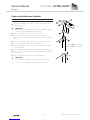
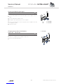
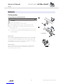
Backrest height
The backrest height can be changed by fitting the telescopic tubes
into another position in the backrest tubes. If this setting option is
insucient, the telescopic tubes can be replaced.
Adjusting the height of standard backrests
Diculty: Tool: Ã 3, 4, 6 8, 10
Push the backrest cover upwards and remove the bolt on
both sides.
Push the push handles upwards or downwards until you reach
the required height. Replace the bolt and tighten.
i If this setting range is insucient, use new push handle tubes.
i If the backrest height was changed considerably, a new backrest
cover may have to be fitted.
Adjusting the height of Velcro® adjustable backrests
Diculty: Tool: Ã 3, 4, 6 8, 10
Remove backrest cover and move the Velcro® bands until bolt
is visible.
Remove bolt and move the push handle tube to the required
height.
Insert bolt into the appropriate hole and tighten.
i If the backrest height is changed considerably, the push handles
must be replaced. An additional Velcro® band may have to be
fitted or one may have to be removed.
1
2
3
4
1
2
3

12
KÜSCHALL ULTRA-LIGHT
© Küschall AG, Switzerland | 2014-07
Service Manual
BACKREST
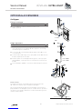
Adjustable-angle backrest
In order to make the backrest angle adjustable, an adjustable-angle
backrest can be fitted.
Backrest angle
Position
Deviation
from standard
backrests
Angle between
backrest and
seat
1 12° 102°
2 8° 98°
3 4° 94°
4 0° 90°
5 -4° 86°
6 -8° 82°
7 -12° 78°
Fitting an adjustable-angle backrest
Diculty: Tool: Ã 3, 4, 5 8, 10 10
Shorter rear frame (variant III) required.
Push the lower joint pin into the rear frame and fix it using a
bolt.
Secure backrest tube to the upper joint pin using a bolt.
Assemble the upper and lower joint pins and and secure
with bolt .
Retighten the bolt .
Set the desired backrest angle and secure in the nearest hole
using bolt .
Push the single Velcro® band and then the other Velcro® bands
and end band over the backrest tube .
Push the push handle into the telescopic tube and fix at the
required height.
Secure end band on the telescopic tube with a bolt.
1
2
3
6
4
5
9
10
7
8
à 13 Nm
à 13 Nm

13
KÜSCHALL ULTRA-LIGHT
© Küschall AG, Switzerland | 2014-07
Service Manual
BACKREST
Setting the backrest angle
Diculty: Tool: Ã 5 10 10
1 Remove the backrest cushion and push the Velcro® bands
upwards, until the backrest joint is invisible.
2 Remove the bolt .
3 Set the desired backrest angle, insert the bolts in the nearest
hole and tighten.
Retighten the bolt .
Perform the same setting on both sides.
Visual check
By looking from the side check that both backrest tubes are level and
thus that the same angle has been set on both sides.
Fitting the joint for a folding backrest
Diculty: Tool: Ã 4, 5 10
Shorter rear frame (variant III) required.
1 Set the desired backrest angle, insert bolt in the nearest
position (Pos. 1, 2 or 3) and tighten. (With the curved backrest
tubes, other positions can be achieved in addition to the
3 positions specified.)
Fold down upper joint pin with intermediate backrest tube .
2 Push the joint housing into the rear frame and fit it using a
bolt.
Backrest angle
Position 1 (rear position): 82°, with curved backrest tube 90°
Position 2 (mid position): 86°, with curved backrest tube 94°
Position 3 (front position): 90°, with curved backrest tube 98°
2
3
1
4
5
1
2
3
4
à 13 Nm
à 13 Nm
à 13 Nm

14
KÜSCHALL ULTRA-LIGHT
© Küschall AG, Switzerland | 2014-07
Service Manual
BACKREST
Replacing push handles / push handles and
backrest
If the push handles are replaced with a dierent type of push handles,
e.g. height-adjustable ones, it can happen that the rear frame must
also be replaced.
Changing the backrest height can also mean that the configuration of
the Velcro® bands must be changed.
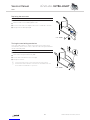
Fitting standard push handles
Diculty: Tools: Ò Ã 3, 4, 5 8, 10
1 Secure the telescopic tube to the rear frame at the required
height.
2 Push the backrest bands and end band onto the telescopic
tube , end band first.
3 Secure end band on the telescopic tube with a bolt.
Fitting height adjustable integrated push handles
Diculty: Tools: Ò Ã 3, 4, 5 8, 10
Special rear frame required for RH 300 – 465 (variant II)
Push lower telescopic tube and upper telescopic tube into
one another and insert bolt.
Secure pre-assembled element (telescopic tubes and ) at the
required height on the rear frame with a bolt (7 Nm).
Push the Velcro® bands and end band onto the telescopic
tubes.
Using the clamp bolt secure the height adjustable push
handles through the telescopic tube .
Push in push handle completely.
Secure end band on the telescopic tube with a bolt.
1
2
4
3
2
1
2
4
5
3
7
6

15
KÜSCHALL ULTRA-LIGHT
© Küschall AG, Switzerland | 2014-07
Service Manual
BACKREST
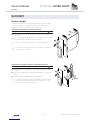
Fitting height adjustable, rear set push handles
Diculty: Tools: Ò Ã 3, 4, 5 8, 10
The Velcro® bands may have to be replaced with narrower ones, as
space is required to secure the holder on the telescopic tube.
Secure the telescopic tube to the rear frame at the required
height.
Press the cover cap onto the end of the telescopic tube.
Push the Velcro® bands onto the telescopic tube.
Push the holder onto the telescopic tube and fix in place by
tightening the clamp bolts.
Fit end band onto the telescopic tube and secure with a bolt.
Attach protective cushion.
Fitting angle-adjustable backrest with height-adjustable
push handles
Diculty: Tools: Ò Ã 3, 4, 5 8, 10 10
Shorter rear frame (variant III) required.
Push the lower joint pin into the rear frame and fix it using
the bolts.
Fit backrest tube onto the upper joint pin using bolts.
Assemble the upper and lower joint pins and and secure
with a bolt .
Set the desired backrest angle and secure in the nearest hole
using a nut and bolt .
Retighten the bolt .
Push the single Velcro® band and then the other Velcro®
bands and end band over the backrest tube .
Push in push handle completely.
Using the clamp bolt a fit the height-adjustable push handles
through the telescopic tube .
Fit end band onto the telescopic tube with a bolt.
1
3
2
5
6
4
1
2
3
4
5
6
9
10
8
7
11
à 13 Nm
à 13 Nm

16
KÜSCHALL ULTRA-LIGHT
© Küschall AG, Switzerland | 2014-07
Service Manual
BACKREST
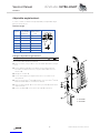
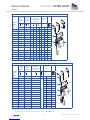
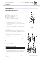
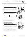
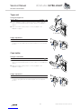
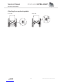
Replacing foldable push handles
Diculty: Tools: Hole punch pliers 6 mm, Ã 3, 4
Remove the old foldable push handle.
Pull down the backrest cover G on the telescopic tube, until its
hole B is uncovered.
! IMPORTANT!
Make sure that the threaded insert F (part no. 1580450) supplied
with the new push handle is used for assembly.
Place the threaded insert F in the telescopic tube.
Punch a hole through the backrest cover with a distance of
10 mm from the upper egde, using hole punch pliers (see graphic
below).
Slide the new foldable push handle A onto the telescopic tube.
Fix the foldable push handle with screw C (M5x12).
Pull up the backrest cover, until it covers completely the rear hole
in the pushhandle.
Fix the foldable push handle with screw D (M5x14) and washer H.
Check screws E on both sides of the push handle and re-tighten
if necessary.
Carry out the same steps for the other push handle.
! IMPORTANT!
Make sure that the folding force is approximately 5 N (0.5 kg).
i
The retrofit of foldable push handles requires new tubing.
C à 3 Nm (low-strength)
D à 7 Nm (low-strength)
10 mm

17
KÜSCHALL ULTRA-LIGHT
© Küschall AG, Switzerland | 2014-07
Service Manual
BACKREST
Angle-adjustable backrest with adjustable backs with respect to push handles
Backrest
height
(RH)
[mm]
Standard
push
handles
Folding
push
handles
Height-
adjustable
integrated push
handles
Velcro
bands
2B
4B
300 S S S
dierent for every backrest height
L 1B+2B S
315 S S S L 1B+2B S
330 S S S S 1B+4B S
345 S S L S 1B+4B S
360 S S L S 1B+4B S
375 S S L L 1B+4B S
390 S/M S/M L L 1B+4B M
405 S/M S/M L L 1B+4B M
420 S/M S/M L L 1B+4B M
435 M M L S 1B+6B M
450 M M L S 1B+6B M
465 M M L S 1B+6B M
480 M M L S 1B+6B L
495 M M L L 1B+6B L
510 M M L L* 1B+6B* L
Assumption: No stabilising bar fitted
* For RH 510 with height-adjustable integrated push handles: =S, =2x4B
Backrest with adjustable backs with respect to push handles
Backrest
height
(RH)
[mm]
Standard
push
handles
Folding
push
handles
Height-
adjustable
integrated push
handles
Velcro
bands
2B
4B
300 S S S XXS S XXS S 4B S
315 S S S XS S XS S 4B S
330 S S S S S S S 4B S
345 S S L M S M L 4B S
360 S S L M S M L 4B S
375 S S L M S M L 4B S
390 S/M S/M L M S M L 4B M
405 S/M S/M L M S M L 4B M
420 S/M S/M L M S M S 6B M
435 M M L L L L S 6B M
450 M M L L L L S 6B M
465 M M L L L L L 6B M
480 M M L L L L L 6B L
495 M M L L L L L 6B L
510 M M L L L L L 6B L
Assumption: No stabilising bar fitted

18
KÜSCHALL ULTRA-LIGHT
© Küschall AG, Switzerland | 2014-07
Service Manual
BACKREST
Foldable angle-adjustable backrest with respect to push handles
Backrest
height
(RH)
[mm]
Standard
push
handles
Folding
push
handles
Height-
adjustable
integrated push
handles
Velcro
bands
2B
4B
300 S S S
dierent for every backrest height
S
dierent for every backrest height
S
315 S S S S S
330 S S S S S
345 S S S S L 2B S
360 S S S S L 2B S
375 S S S S L* 2B S
390 S S L S L 2B M
405 S S L S S 4B M
420 S S L S S 4B M
435 M M L S S 4B M
450 M M L L S 4B M
465 M M L L L 4B M
480 M M L L L 4B L
495 M M L L L 4B L
510 M M L L L 4B L
Assumption: No stabilising bar fitted
* For RH 375 with height-adjustable integrated push handles: =S und =2B+4B
Additionally a band is fixed close to the backrest joint. The band is of dierent length according to
the seat width (SB).
There are 3 lengths: SB 280 - 360 short,
SB 380 - 440 medium,
SB 460 - 500 long.

19
KÜSCHALL ULTRA-LIGHT
© Küschall AG, Switzerland | 2014-07
Service Manual
FOOTRESTS
FOOTRESTS
One-piece and two-piece footrests are available.
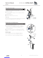
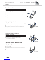
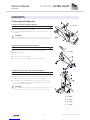
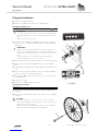
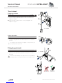
One-piece footrest
Replacing the footplate
Diculty: Tool: Ã 4 10
Loosen bolts on both
sides.
Remove footplate and
replace with a new one.
Re-insert bolts and
tighten.
Disassembling/fitting the footrest
Diculty: Tool: Ã 4 8
1 Remove bolts on both sides.
2 Pull out the footrest.
3 Insert new footrest.
4 Tighten bolts on both sides at the same height and in the
required position.
Adjusting the height of the footrest
Diculty: Tool: Ã 4 8
1 Remove bolts on both sides.
2 Hold the telescopic tubes with both hands and push the
footrest into the required position.
3 Insert bolts into the nearest hole on both sides and at the same
height and tighten securely.
1
2
1
1
à 13 Nm
à 4 Nm
à 4 Nm

20
KÜSCHALL ULTRA-LIGHT
© Küschall AG, Switzerland | 2014-07
Service Manual
FOOTRESTS
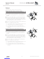
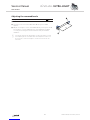
Centring and adjusting the angle
Diculty: Tool: Ã 4 10
Loosen bolts and slightly.
1 Set the same distance from the side tube to the footplate on both
sides.
2 Set the required footplate incline.
Re-tighten bolts (fixed side of the footplate).
Turn the little tube on the moving side of the footplate such that
it engages properly.
Tighten bolts .
Changing the position of the footrest
(set to rear – set to front)
Diculty: Tool: Ã 4 10
1 Loosen bolts on both sides and remove.
2 Turn the footplate with the clamp component.
3 Re-insert bolts and tighten.
1
2
3
1
à 13 Nm
à 13 Nm
à 13 Nm
La page charge ...
La page charge ...
La page charge ...
La page charge ...
La page charge ...
La page charge ...
La page charge ...
La page charge ...
La page charge ...
La page charge ...
La page charge ...
La page charge ...
La page charge ...
La page charge ...
La page charge ...
La page charge ...
La page charge ...
La page charge ...
La page charge ...
La page charge ...
-
 1
1
-
 2
2
-
 3
3
-
 4
4
-
 5
5
-
 6
6
-
 7
7
-
 8
8
-
 9
9
-
 10
10
-
 11
11
-
 12
12
-
 13
13
-
 14
14
-
 15
15
-
 16
16
-
 17
17
-
 18
18
-
 19
19
-
 20
20
-
 21
21
-
 22
22
-
 23
23
-
 24
24
-
 25
25
-
 26
26
-
 27
27
-
 28
28
-
 29
29
-
 30
30
-
 31
31
-
 32
32
-
 33
33
-
 34
34
-
 35
35
-
 36
36
-
 37
37
-
 38
38
-
 39
39
-
 40
40


