Kuschall Champion Manuel utilisateur
- Catégorie
- Poussettes
- Taper
- Manuel utilisateur


3
KÜSCHALL CHAMPION
© Küschall AG, Switzerland | 2014-12
Service Manual
TABLE OF CONTENTS
GENERAL ...................................................................................................................... 4
Introduction 4
Spare parts and adaptations 4
Tightening Allen screws 4
Torque 5
Checks 5
Identifying and alleviating malfunctions 5
OVERVIEW ....................................................................................................................6
Components 6
Dimensions 6
FRAME ............................................................................................................................7
Changing Frame 7
SEAT .............................................................................................................................. 8
Fitting seat cover to frame 8
Front seat height (SHv) 8
Rear seat height (SHh) 9
Checking the folding unit 10
Adjusting the folding unit 10
BACKREST ...................................................................................................................11
Tension adjustable backrest 11
Backrest height (RH) 14
Backrest angle (RW) 15
Push handles / backrest telescopes 15
Replacing foldable push handles 17
Stabilisation bar 17
FOOTRESTS ................................................................................................................18
Lower leg length (UL) 18
Footplate 19
SIDE PARTS .................................................................................................................21
Clothes-guard assembly 21
Mud guard assembly 23
Siderest assembly and adjustment 24
FRONT WHEELS ........................................................................................................ 25
Replacing a front wheel 25
Replacing a front wheel fork 25
Setting the angle of the caster attachment 26
Checking and adjusting the alignment of the supporters 26
Shift supporter on the frame 26
REAR WHEELS ........................................................................................................... 27
Rear wheels, repositioning 27
Wheel camber, adapter sleeves 27
Adjusting the removable axle 27
Distance sleeves 28
Adapterplate, adjustment to folding unit or assembly of new adapter plate 28
BRAKES ....................................................................................................................... 29
Fitting / adjusting the parking brake 29
Antitipper / Transit wheels 30
Tipper aid / Cane holder 31
Fitting the pelvic belt 31

4
KÜSCHALL CHAMPION
© Küschall AG, Switzerland | 2014-12
Service Manual
GENERAL
Introduction
This service manual is part of the instructions and contains the tech-
nical information for servicing, configuring and repairing a küschall®
wheelchair.
WARNING!
Danger of accident and severe injuries.
If the wheelchair is improperly set it can cause
accidents and severe injuries.
▸Changes to the wheelchair may only be carried out
by the dealer.
To guarantee the required safety and reliability, all wheelchairs must
be comprehensively checked once a year.
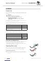
In part, assembly and adjustment require extensive experience. For
this reason, the following assembly instructions have been split into
three categories:
Requirement Symbol
Easy – technical understanding required
Intermediate – specialist knowledge required
Dicult – specialist wheelchair assembly knowledge
and experience required
The required tools and their respective sizes are listed above each
instruction. The instructions include information on the torques with
which the respective screw connections must be tightened. Adhering
to the given torques requires the use of a torque spanner.
Tools Symbol
Allen key à 2x3, 4, 5, 6
Phillips screwdriver Ò 2
Straddle spanner 19, 11
Socket spanner/ring spanner 8, 10, 14, 22
Spare parts and adaptations
All spare parts can be purchased from küschall®'s Customer Services.
An electronic spare parts catalog is available by logging onto
www.kuschall.com. Only original spare parts may be used.
Installing additional adaptations to a küschall® wheelchair requires
the prior written approval of Küschall AG.
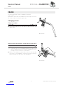
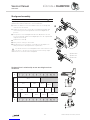
Tightening Allen screws
Allen keys are not designed for greater forces. When tightening or
loosening an Allen screw, it is therefore advisable to apply force to
the nut to prevent the hexagon socket from being damaged.
Tightening and loosening
Turn the nut with a socket spanner (only use a straddle spanner
if there is insucient space) and merely hold the screw tight with
the Allen key.

5
KÜSCHALL CHAMPION
© Küschall AG, Switzerland | 2014-12
Service Manual
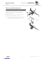
Tightening and loosening if there is no nut
If an Allen screw is directly screwed into a screw thread, the screw must be tightened
using an Allen key.
i Ensure that the Allen key is of good quality and
not worn.
Torque
All screw connections must be tightened with the torques specified in the following
instructions.
Checks
Visual check
Check all components for cracks, especially the areas around joints and welded seams.
Checking the screw connections
Check all bolts with the torques specified in the instructions regularly, and adjust if
required.
CAUTION!
Several screw connections have been secured with thread locking adhesive. If these are
opened, they must be secured again using new thread locking adhesive.
High-strength and low-strength adhesives are available. For torque entries notice shall be
made whether an adhesive and which adhesive needs to be used.
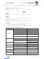
Identifying and alleviating malfunctions
Malfunction Possible cause Measure
The wheelchair will not
move in a straight line
Incorrect tire pressure in a rear wheel Correct tire pressure
One or more spokes broken Replace defective spoke(s)
Spokes unevenly tensioned Tighten excessively loose spokes
Dirty or damaged wheel bearings Clean or replace bearings
Bearing block of castor fork is not vertical Align bearing block vertically
Front wheels not set to the same height
Position the front wheels in such a way
that they touch the ground at the same
time
Rear wheels not parallel or axes not aligned Adjust the prestress load on the scissor
mechanism and/or the trail
The wheelchair tips
backwards too easily
Rear wheels have been fitted too far forward Fit rear wheels further back
Backrest angle too great Reduce backrest angle
Seat angle too great
Mount the adapter plate lower on the
side profile
Mount the smaller castor fork
The brakes engage poorly
or asymmetrically
Incorrect tire pressure in one or both rear wheels Correct tire pressure
Brake setting incorrect Correct brake setting
Roll resistance is too great Insucient tire pressure in the rear wheels Correct tire pressure
Rear wheels are not parallel Ensure that the rear wheels are parallel
The front wheels wobble
when moving fast
Insucient tension in the front wheel bearings block Lightly tighten the nut in the bearings
block axle
Front wheel is worn flat Replace front wheel
The front wheel is sti or
stuck Dirty or damaged bearings Clean or replace the bearings
The wheelchair is very
dicult to unfold The backrestcover is too tight Loosen the backrestbands a little
Handling seems imprecise The scissor mechanism is not closed properly If required, remove dirt from scissor
mechanism
The scissor mechanism is misaligned Realign the scissor mechanism

6
KÜSCHALL CHAMPION
© Küschall AG, Switzerland | 2014-12
Service Manual
OVERVIEW
OVERVIEW
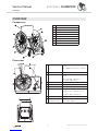
Components
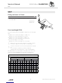
Dimensions
ASeat depth 340 – 480 mm, in increments of 20 mm
(AL / TI)
400 – 460 mm, in increments of 20 mm
(C)
BBackrest angle 76°/80,5°/85°/89,5°/94°
CKnee-to-heel length 220 – 500 mm, in increments of 10 mm
(AL / TI)
300 – 340 / 400 – 500 mm, in
increments of 10 mm (C)
DSeat height front 450 – 540 mm, stepless adjustable
ESeat height rear 390 – 490 mm, stepless adjustable
FBackrest height 300 – 465 mm, in increments of 15 mm
GTotal length 75°: approx. 825 – 1190 mm (AL / TI)
90°: approx. 775 – 1140 mm (AL / TI)
85°: approx. 800 – 1165 mm (C)
HSeat width 340 – 480 mm, in increments of 20 mm
ITotal width
Total width, folded
Seat width plus 160 – 240 mm
approx. 280 – 340 mm
AL = Aluminium / TI = Titanium / C = Carbon
ABackrest
BRear wheel with handrim
CQuick release axle
DFolding mechanism
EFront wheel fork with front wheel
FFootrest
GFrame
HSeat
IMudguard

7
KÜSCHALL CHAMPION
© Küschall AG, Switzerland | 2014-12
Service Manual
FRAME
FRAME
The küschall Champion frame is available in aluminium,
titan or carbon.
Aluminium or titan frames are available with frame angles of 75° and
85°, carbon frames with a frame angle of 85°
Changing Frame
Fitting frame tubes
Diculty: Tools: Ã 4 10
Fit both frame tubes into the side supporters A using bolts B and
tighten lightly.
Attaching the side supporters, frame tubes and seat cover
Diculty: Tools: Ã 5 10
i The purpose of the threaded connection through the frame
mounting holes is to provide additional fixing. The frame is thus
easier to guide and is better secured. Any misalignment of the
toe angle of the front wheels is counteracted.
Attach the side supporters, frame tubes, seat cover and optionally,
the holders for the mudguard or siderests using bolts through the
frame mounting holes F on both sides and tighten.
B à 13 Nm
F à 13 Nm

8
KÜSCHALL CHAMPION
© Küschall AG, Switzerland | 2014-12
Service Manual
SEAT
SEAT
Fitting seat cover to frame
Diculty: Tools: Ã 3, 4 10
Fit seat cover to side supports and frame on both sides using
bolts A and B.
Front seat height (SHv)
The following possibilities are available to adjust the front seat height
(SHv):
- Replace the front wheel with a larger or smaller one,
Chap. Front wheels; Replacing a front wheel.
- Replace the front fork with a larger or smaller one,
Chap. Front wheels; Replacing a front wheel fork.
- Move the side support on the frame,
Chap. Front wheels; Shift supporter on the frame.
i Adjusting the front seat height changes the seat angle. It may be
necessary to adjust the rear seat height correspondingly.
i It must be ensured that the rear wheels are parallel after changing
the
front seat height. If required, they must be readjusted,
Chap. Rear wheels; Adjustment of rear wheel parallelism.
After adjusting the front seat height the verticality of the castor pins
need to be checked and adjusted if neccessary, Chap. Front
wheels; Checking and adjusting the alignment of the supporters.
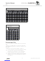
Front seat height (SHv) per frame size, castor fork and front wheel
SHv
[mm]
Aluminium / Titan frame 75°
(long frame) (short frame)
ST 40-48 ST 34-38 ST 40-48 ST 34-38
3'' 4'' 5'' 3'' 4'' 5'' 3'' 4'' 5'' 3'' 4'' 5''
540 - - - ------
530 - ------
520 ------
510 - - ---
500 - - -
490 -
480
470
460
450
A à 13 Nm
B à 5 Nm

9
KÜSCHALL CHAMPION
© Küschall AG, Switzerland | 2014-12
Service Manual
SEAT
Front seat height (SHv) per frame size, castor fork and front wheel
SHv
[mm]
Aluminium / Titan frame 85°
(long frame) (short frame)
ST 40-48 ST 34-38 ST 40-48 ST 34-38
3'' 4'' 5'' 3'' 4'' 5'' 3'' 4'' 5'' 3'' 4'' 5''
540 - - - ------
530 - ------
520 ------
510 - - - - -
500 - - -
490 -
480
470
460
450
Front seat height (SHv) per frame size, front
fork and front wheel
SHv
[mm]
Carbon frame 85°
UL 400 – 500
450 3''
460 4'' 3''
480 4'' 3''
490 5'' 4'' 3''
500 5'' 4'' 3''
510 5'' 4'' 3''
520 5'' 4''
530 5'' 4''
540 5''
Rear seat height (SHh)
The following possibilities are available to adjust the rear seat height
(SHh):
- Adjustment of the adapter plate to the folding unit, Chap. Rear
wheels; Adapterplate, adjustment to folding unit or assembly of new
adapterplate.
- Replacement of the rear wheel with a larger or smaller one.
i It must be ensured that the rear wheels are parallel after changing
the rear seat height, If required, they must be readjusted,
Chap. Rear wheels; Adjustment of rear wheel parallelism.
i It must be ensured that the the castor pins are vertical after
changing the rear seat height, If required, they must be readjusted,
Chap. Front wheels; Checking and adjusting the alignment
of the supporters.

10
KÜSCHALL CHAMPION
© Küschall AG, Switzerland | 2014-12
Service Manual
SEAT
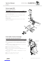
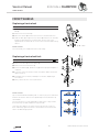
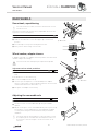
Checking the folding unit
Diculty: Tools: Ã 5
The bolt A of the scissor mechanism must be checked regularly for
play.
The scissor mechanism must open and close easily.
Check that the retaining rings B are sitting well, replace if
neccessary.
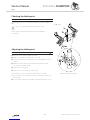
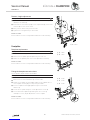
Adjusting the folding unit
Diculty: Tools: Ã3 16
Remove the end-stop nut C from bolt E.
Apply new thread locking adhesive on bolt E.
Screw the end-stop nut completely on the bolt again, but do not
tighten.
Adjust the end stop F of the folding unit by tightening resp.
loosening the grub screw D.
Tighten the end-stop nut.
Carry out the same settings on both sides.
Check that the scissor mechanism opens and closes easily.
Check the seat cover for sucient tension in unfolded condition of
the wheelchair.
If neccessary, repeat the steps above until all settings are correct.
A à 4 Nm
C à 13 Nm (high-strength)

11
KÜSCHALL CHAMPION
© Küschall AG, Switzerland | 2014-12
Service Manual
BACKREST
BACKREST
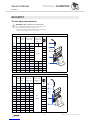
Tension adjustable backrest
Tension adjustable backrest with foldable push handles
RH
[mm]
teles-
copic
tube
Inter-
mediate
tube
Velcro straps
without
stabili-sation
bar
Velcro
straps with
stabilisation
bar
S
M
L
not
possible
300 S S L M S
315 S S L S+M S
330 S L L S+M S
345 S L L S+M M
360 S L L S+M M
375 S L L L M
390 S L L L M
405 L L L L L
420 L L L S+L L
435 L L L S+L L
450 L L L S+L L
465 L L L S+L L
Tension adjustable backrest with push handles standard
RH
[mm]
Push-
handle
Inter-
mediate
tube
Velcro straps
without stabili-
sation bar
Velcro
straps with
stabilisation
bar
S=5cm
L=10cm
S
M
L
300 S S L M
not
possible
S
315 S S L M S
330 S L L S+M S
345 S L L S+M M
360 S L L S+M M
375 S L L S+M M
390 S L L L M
405 L L L L S S+L L
420 L L L L S S+L L
435 L L L S+L S S+L L
450 L L L S+L S S+L L
465 L L L S+L S M+L L
IMPORTANT! Risk of damage to the wheelchair.
A too tight band installation may cause damage to the
backrest when unfolding the wheelchair.
▸Make sure that the backrest bands are only adjusted
in unfolded condition of the wheelchair.

12
KÜSCHALL CHAMPION
© Küschall AG, Switzerland | 2014-12
Service Manual
BACKREST
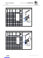
Tension adjustable backrest without push handles
RH
[mm]
Teles-
copic
tube
Inter-
mediate
tube
Velcro straps
without
stabili-sation
bar
Velcro
straps with
stabilisation
bar
S=5cm
L=10cm
S
M
L
300 S S L M
not
possible
S
315 L S L S+M S
330 L S L S+M S
345 L S L S+M M
360 L S L S+M M
375 L L L L M
390 L L L L M
405 L L L L S L L
420 L L L S+L S S+L L
435 L L L S+L S S+L L
450 XL L L S+L S S+L L
465 XL L L S+L S S+L L
Tension adjustable backrest with rearset push handles height adjustable
RH
[mm]
Teles-
copic
tube
Inter-
mediate
tube
Velcro straps
without
stabili-sation
bar
Velcro
straps with
stabilisation
bar
S=5cm
L=10cm
S
M
L
300 S S S M
not
possible
S
315 L S S M S
330 L S L M S
345 L S L M M
360 L S L M M
375 L L S 2xM M
390 L L S 2xM M
405 L L L 2xM S M L
420 L L L 2xM S M L
435 L L L 2xM S S+M L
450 XL L L 2xM S S+M L
465 XL L L 2xM S S+M L

13
KÜSCHALL CHAMPION
© Küschall AG, Switzerland | 2014-12
Service Manual
BACKREST
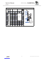
Tension adjustable backrest with push handles, height adjustable
RH
[mm]
Push-
handle
Backrest-
tube
Velcro straps
without
stabilisation bar
Velcro
straps with
stabilisation bar
S=5cm
L=10cm
S
M
L
300
Standard push handle
S L M
not
possible
S
315 S L S+M S
330 M L S+M S
345 M L S+M M
360 M L 2xM M
375 M L 2xM M
390 M L 2xM M
405 L L S+2xM S S+2xM L
420 L L S+2xM S S+L L
435 L L S+L S S+L L
450 L L S+L S S+L L
465 L L S+L S M+L L

14
KÜSCHALL CHAMPION
© Küschall AG, Switzerland | 2014-12
Service Manual
BACKREST
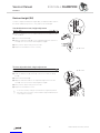
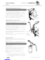
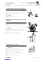
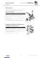
Backrest height (RH)
In order to adjust the backrest height (RH), the backrest tubes have to
be fixed in a dierent position or they have to be exchanged.
Standard backrest cover, height adjustment
Diculty: Tools: Ã3 8
Push the backrest cover so that bolt and nut on the backrest tube
are revealed.
Remove bolt and nut A.
Adjust the backrest tube B to the required height then insert the
screw A into the closest hole and tighten it again.
Carry out the same setting on both sides.
Reposition the backrest cover correctly.
Tension adjustable back, height adjustment
Diculty: Tools: Ã3 8
Remove the backrest cover A.
Slide the backrest straps either up or down to locate the fixing
bolt B.
Remove bolt and nut B.
Adjust the backrest tube to the required height then insert the
screw B into the closest hole and tighten it again.
Carry out the same setting on both sides.
Reposition the backrest cover.
i In the case of major changes of the backrest height (RH), bands
may have to be inserted or removed and a larger/smaller backrest
cover may be necessary.
A
B
A à 7 Nm
A
B
B à 7 Nm

15
KÜSCHALL CHAMPION
© Küschall AG, Switzerland | 2014-12
Service Manual
BACKREST
Backrest angle (RW)
Backrest, angle adjustment
Diculty: Tools: Ã4 10
Remove the lower bolt A from the side supporter B and move
the backrest C to the required position. The spacer D remaines
fixed in the latch bolt E.
Insert bolt and nut A into the closest hole and tighten it again.
Carry out the same setting on both sides.
Function control:
The backrest must fold easily and the ratchet bolt must sit tightly
against the side supporter.
Push handles / backrest telescopes
Push handle / telescopic tube replacement
Diculty: Tools: Ã3 8 Ò2
Remove the backrest cover A.
Remove the screws C holding the uppermost backrest band B
(or standard backrest cover) to the push handles E (or telescopic
tubes).
Slide the backrest straps D (or standard backrest cover) either up
or down to locate the fixing bolt F.
Remove bolts and nuts on both sides F.
Remove push handles E (or telescopic tubes).
Slide new push handle through backrest band B and fix it on the
backrest with bolt F.
Fix the upmost backrest band B (or standard backrest cover) with
screws C.
Carry out the same setting on both sides.
Reposition the backrest cover correctly.
A à 13 Nm
C à 4 Nm
F à 7 Nm

16
KÜSCHALL CHAMPION
© Küschall AG, Switzerland | 2014-12
Service Manual
BACKREST
Height adjustable integrated push handles
Diculty: Tools: Ã3 8 Ò2
Fit the backrest tube A corresponding to the desired backrest
height (RH) on both sides using the bolts B.
Slide the backrest bands C corresponding to the desired backrest
height (RH) and, if required, the end band D (or the standard
backrest cover) over the backrest tube A.
Slide the push handle F into the backrest tube A on both sides
and secure it at the desired height using the clamp bolt G.
Secure the end band D (or the standard backrest cover) to the
backrest tube A on both sides using the screws E.
Height adjustable rear set push handles
These push handles can only be used in combination with adjustable
backrests, not with standard backrests.
Diculty: Tools: Ã3 8 Ò2
Fit the intermediate tube A on both sides using the bolts B.
Slide the backrest bands C corresponding to the desired backrest
height (RH) onto the intermediate tube A.
Fit the telescopic tube D corresponding to the desired backrest
height (RH) on both sides using the bolt E.
Slide the holder F and the sleeve G onto the telescopic tube D
and secure it using the screws H.
For the minimum backrest height, the holder of the rear set push
handle must be fitted to the intermediate tube A. In this case, the
sleeve G is not required.
Slide the end band I onto the telescopic tube D and secure it on
both sides using the screws J.
Replacing the handle
An adhesive (e.g. hair spray) is used in these instructions. When
applied to the handle, this substance works as a lubricant and as an
adhesive once dry.
After drying, the adhesive used must be able to resist a pull-o
force of 750 N. If in doubt, contact Küschall® AG.
Diculty:
Remove the old handle.
Remove any residue (residual adhesive, grease, dust) from the
push handle tube.
Apply a thin layer of hair spray all over the surface of the push
handle tube onto which the handle is to be slid.
Apply a thin layer of hair spray to the inside of the handle.
Slide the new handle onto the push handle tube.
Move the handle into the correct position (grooves facing
upwards).
i
If a long handle has been fitted and this is to be replaced with a
short one, the push handle tube must be shortened by 35 mm.
The push handle tube must be replaced when switching from a
short to a long handle.
B à 7 Nm
E à 4 Nm
B à 7 Nm
E à 7 Nm
H à 13 Nm
J à 4 Nm

17
KÜSCHALL CHAMPION
© Küschall AG, Switzerland | 2014-12
Service Manual
BACKREST
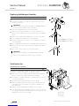
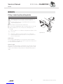
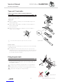
Replacing foldable push handles
Diculty: Tools: Hole punch pliers 6 mm, Ã 3, 4
Remove the old foldable push handle.
Pull down the backrest cover G on the telescopic tube, until its
hole B is uncovered.
IMPORTANT!
Make sure that the threaded insert F (part no. 1580450) supplied
with the new push handle is used for assembly.
Place the threaded insert F in the telescopic tube.
Punch a hole through the backrest cover with a distance of
10 mm from the upper egde, using hole punch pliers (see graphic
below).
Slide the new foldable push handle A onto the telescopic tube.
Fix the foldable push handle with screw C (M5x12).
Pull up the backrest cover, until it covers completely the rear hole
in the pushhandle.
Fix the foldable push handle with screw D (M5x14) and washer H.
Check screws E on both sides of the push handle and re-tighten
if necessary.
Carry out the same steps for the other push handle.
IMPORTANT!
Make sure that the folding force is approximately 5 N (0.5 kg).
i
The retrofit of foldable push handles requires new tubing.
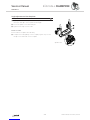
Stabilisation bar
Stabilisation bar assembly
Diculty: Tools: Ã38 Ò2
With a back height RH405 or larger it is possible to assemble a stabili-
sation bar to increase the rigidity of the backrest handles.
Remove backrest cover A, push handles B and 10 cm backrest
band (or end band, if no push handles are assembled).
Assemble a 5 cm backrest band C or end band with the screws L
to the push handles B.
Assemble the push handles B with bolts and nuts K.
Attach the clamps D together with the RH socket F and the LH
socket H with the screws G below the backrest band C to the
push handles B.
Replace the push handle/backrest band/socket assembly.
Press pin E and slide the stabilisation bar J into the RH socket F
then swing the stabilisation bar upwards, press pin I and click the
stabilisation bar into the LH socket H.
C à 3 Nm (low-strength)
D à 7 Nm (low-strength)
G à 4 Nm
K à 7 Nm
L à 4 Nm
10 mm

18
KÜSCHALL CHAMPION
© Küschall AG, Switzerland | 2014-12
Service Manual
FOOTRESTS
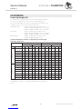
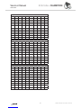
Possible footplate situations in relationship to seat angle
and front wheel size
Set to front Set to rear
ST340 - ST380 ST400 - ST480 ST340 - ST380 ST400 - ST480
Seat angle 3“ 4“ 5“ 3“ 4“ 5“ 3“ 4“ 5“ 3“ 4“ 5“
Frame 75°
0 mm
10 mm
20 mm
30 mm
40 mm
50 mm
60 mm
70 mm
Frame 85°
30 mm
40 mm
50 mm
60 mm
70 mm
80 mm
90 mm
100 mm
If the knee-to-heel length is smaller than seat height front (SHv) mi-
nus 100 mm, there are no conflicts possible between footplate and
castors.
FOOTRESTS
Lower leg length (UL)
To change the lower leg length, the footrest can be fixed at a higher or
lower position, Chap. Footrests, Footrest, height adjustment.
Short lower leg lengths (UL) can be set using a high-mounted footrest,
Chap. Footrests, Footrest mounted in high position.
Aluminium frame: UL220 – UL310 high mounted footrest
UL320 – UL390 standard footrest, short frame
UL400 – UL500 standard footrest, long frame
Titan frame: UL220 – UL340 high mounted footrest
UL360 – UL390 standard footrest, short frame
UL400 – UL500 standard footrest, long frame
Carbon frame: UL300 – UL340 high mounted footrest
UL400 – UL500 standard footrest

19
KÜSCHALL CHAMPION
© Küschall AG, Switzerland | 2014-12
Service Manual
FOOTRESTS
Footrest, height adjustment
Diculty: Tools: Ã4 8
Remove on both sides bolt and nut A, which fix the telescopic
tube B to the frame C.
Extend the footrest telescope B to the required length, then insert
the bolts A into the closest holes.
Carry out the same setting on both sides.
Tighten the locking bolts A on both sides.
Function control
Check that the footrest is firmly attached but that it can fold easily.
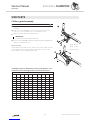
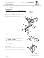
Footplate
Footplate replacement
Diculty: Tools: Ã4 8
Remove the screws A and the screws B.
Remove the footplate C and replace it by the new one.
Attach the footplate C with the screws A and the screws B.
Function control
Check that the footrest is firmly attached but that it can fold easily.
Fitting the footplate set to the front
The footplate is fitted set back as standard.
Diculty: Tools: Ã4, 5
Remove the screws A and the screws B.
Remove the screws and washers C on both sides.
Rotate the footplate mounting D by 180°. The elongated side of
the footplate mounting D is now pointing forwards.
Fit the footplate mounting D again using the screws and
washers C.
Secure the footplate using the screws A and the screws B.
Set the desired footplate angle and tighten the screws C,
Chap. Footrests, Angle adjustment of the footplate.
Function control
Check that the footrest is firmly attached but that it can fold easily.
A à 7 Nm
A à 7 Nm
B à 7 Nm
A à 7 Nm
B à 7 Nm
C à 7 Nm

20
KÜSCHALL CHAMPION
© Küschall AG, Switzerland | 2014-12
Service Manual
FOOTRESTS
Angle adjustment of the footplate
Diculty: Tools: Ã 4, 5 8
Slightly loosen the bolts A under the footplate which secure the
telescopic tube B to the footplate mounting C.
Set the footplate to the desired angle.
Tighten the bolt A on both sides.
Function control
Check that the footplate can fold easily.
To adjust the folding ability of the footplate, tighten resp. loosen
nut D on the underside of the footplate.
A à 7 Nm
La page est en cours de chargement...
La page est en cours de chargement...
La page est en cours de chargement...
La page est en cours de chargement...
La page est en cours de chargement...
La page est en cours de chargement...
La page est en cours de chargement...
La page est en cours de chargement...
La page est en cours de chargement...
La page est en cours de chargement...
La page est en cours de chargement...
La page est en cours de chargement...
-
 1
1
-
 2
2
-
 3
3
-
 4
4
-
 5
5
-
 6
6
-
 7
7
-
 8
8
-
 9
9
-
 10
10
-
 11
11
-
 12
12
-
 13
13
-
 14
14
-
 15
15
-
 16
16
-
 17
17
-
 18
18
-
 19
19
-
 20
20
-
 21
21
-
 22
22
-
 23
23
-
 24
24
-
 25
25
-
 26
26
-
 27
27
-
 28
28
-
 29
29
-
 30
30
-
 31
31
-
 32
32


Kuschall Champion Manuel utilisateur
- Catégorie
- Poussettes
- Taper
- Manuel utilisateur
dans d''autres langues
- English: Kuschall Champion User manual
Documents connexes
Autres documents
-
Quickie Q7® Le manuel du propriétaire
-
Sunrise Medical 7 Series Le manuel du propriétaire
-
-
-
Invacare Alu Lite Manuel utilisateur
-
Vermeiren Trigo T Manuel utilisateur
-