KYLAND Opal5G Guide d'installation
- Catégorie
- Commutateurs réseau
- Taper
- Guide d'installation
Ce manuel convient également à

Opal5G/Opal10G Series Entry-Level Industrial Ethernet
Switch Hardware Installation Manual
Publication Date: Nov. 2018
Version: V1.3
No.: 112023038

Certificate of Compliance
EU Directive 2011/65/EU (RoHS-Directive)
Dear Ladies and Gentlemen,
According to the EU Directive 2011/65/EU the use of several substances for electrical and
electronic equipment in defined categories is restricted. Kyland hereby declares that the
parts used in our products are produced in full compliance with the Directive 2011/65/EU
“Restriction of the Use of Certain Hazardous Substances in Electrical and Electronic
Equipment” (RoHS), including all amendments to the EU-directive (e.g. The Restrictions of
DecaBDE).
This information and our technical advice – whether verbal, in writing or by way of trials – are given in
good faith and to the best of our knowledge but without liability and warranty, unless law admits the
liability or warranty. This also applies where proprietary rights of third parties are involved. Our advice
does not release you from the obligation to check its validity and to test our products as to their suitability
for the intended processes and applications. The application, use and processing of our products and the
products manufactured by you on the basis of our technical advice are beyond our control and, therefore,
entirely your own responsibility. Our products are sold in accordance with the current version of our
General Conditions of Sale and Delivery.
Disclaimer: Kyland Technology Co., Ltd. tries to keep the content of this manual as
accurate and as updated as possible. This document is not guaranteed to be error-free, and
we reserve the right to amend it without notice to users.
All rights reserved.
No part of this documentation may be excerpted, reproduced, translated, annotated or
duplicated, in any form or by any means without the prior written permission of Kyland
Corporation.
Copyright © 2018 Kyland Technology Co., Ltd.

Notice for Safety Operation
The product performs reliably as long as it is used according to the guidance. Artificial
damage or destruction of the device should be avoided. Before using the device, read this
notice carefully for personal and equipment safety. Please keep the manual for further
reference. If the device used not according to the specified way by Kyland, the protection
provided by the device maybe diminished. And Kyland is not liable to any personal or
equipment damage caused by violation of this notice.
Ensure the area where the device is used is clean and dry. Keep the ambient relative
humidity within the range from 5% to 95% (non-condensing).Be suitable for indoor use.
Do not place the device in an environment with high magnetic field, strong shock, or high
temperature. Keep the working and storage temperatures within the allowed range.
Install and place the device securely and firmly.
Please keep the device clean; if necessary, wipe it with a soft cotton cloth.
Do not place any irrelevant materials on the device or cables. Ensure adequate heat
dissipation and tidy cable layout without being entangled or knotted.
Wear antistatic gloves or take other protective measures when operating the device.
Avoid any exposed metal wires because they may be oxidized or electrified.
Install the device in accordance with related national and local regulations.
Before power-on, make sure the power supply is within the allowed range of the device.
High voltage may damage the device.
Power connectors and other connectors should be firmly interconnected.
Do not plug in or out the power supply with wet hands. When the device is powered on,
do not touch the device or any parts with wet hands.
Before operating a device connected to a power cable, remove all jewelry (such as rings,
bracelets, watches, and necklaces) or any other metal objects, because they may cause
electric shock, burns, or welding.
Do not operate the device or connect or disconnect cables during an electrical storm.
Use compatible connectors and cables. If you are not sure, contact our sales or
technical support personnel for confirmation.
Do not disassemble the device by yourself. When an anomaly occurs, contact our sales
or technical support personnel.
If any part is lost, contact our sales or technical support personnel to purchase a
replacement. Do not purchase parts from other channels.
Dispose of the device in accordance with relevant national provisions, preventing

environmental pollution.
Note:The security of any system merged with this device is the responsibility of the
assembler.
In the following cases, please immediately shut down your power supply and contact your
Kyland representative:
Water gets into the equipment.
Equipment damage or shell damage.
Equipment operation or performance has abnormally changed.
The equipment emits odor, smoke or abnormal noise.
The following information applies when operating this device in hazardous locations:
Suitable for use in Class I, Division 2, Groups A, B, C and D Hazardous Locations, or
nonhazardous locations only.
Cet appareillage est utilisable dans les emplacements de Classe I, Division 2, Groupes A, B,
C et D, ou dans les emplacements non dangereux seulement.
WARNING: EXPLOSION HAZARD
Do not disconnect equipment while the circuit is live or unless the area is known to be
free of ignitable concentrations.
Substitution of any component may impair suitability for Class I, Division 2.
AVERTISSEMENT: RISQUE D'EXPLOSION
Avant de deconnecter l'equipement, couper le courant ou s'assurer que l'emplacement
est designe non dangereux.
La substitution de composants peut rendre ce materiel inacceptable pour les
emplacements de Classe I, Division 2.
NOTE: This equipment has been tested and found to comply with the limits for a Class A
digital device, pursuant to part 15 of the FCC Rules. These limits are designed to provide
reasonable protection against harmful interference when the equipment is operated in a
commercial environment. This equipment generates, uses, and can radiate radio frequency
energy and, if not installed and used in accordance with the instruction manual, may cause
harmful interference to radio communications. Operation of this equipment in a residential
area is likely to cause harmful interference in which case the user will be required to correct
the interference at his own expense.

1
Contents
1 Product Overview.............................................................................................................................2
2 Structure and Interface....................................................................................................................3
2.1 Front Panel................................................................................................................................ 3
2.2 Top Panel...................................................................................................................................4
3 Mounting............................................................................................................................................5
3.1 Dimension Drawing.................................................................................................................. 5
3.2 Mounting Modes and Steps.................................................................................................... 6
3.2.1 DIN-Rail Mounting............................................................................................................. 6
3.2.2 DIN-Rail Dismounting....................................................................................................... 7
4 Connection........................................................................................................................................ 8
4.1 10/100/1000Base-T(X) Ethernet Port....................................................................................8
4.2 1000Base-X SFP slot...............................................................................................................9
4.3 Grounding................................................................................................................................ 11
4.4 Power Terminal Block............................................................................................................ 11
4.5 DIP Switches........................................................................................................................... 13
5LEDs
................................................................................................................................................ 14
6 Basic Features and Specifications..............................................................................................15
7 Certificates Used for Compliance................................................................................................16
8 Appendix......................................................................................................................................... 17

Product Overview
2Kyland Opal5G/Opal10G IM-EN-June 2016
1 Product Overview
Opal5G/Opal10G entry-level industrial Ethernet switches are specially designed for
industrial control applications.Opal5G/Opal10G supports normal-temperature-range and
wide-temperature-range models. Broadcast storm protection and Jumbo frame transmission
can be configured through DIP switches.
The series switches support DIN rail mounting. Opal5G provides five 10/100/1000Base-T(X)
Ethernet ports; Opal10G provides two 1000Base-X SFP slots (Gigabit SFP Slot), and eight
10/100/1000Base-T(X) Ethernet ports. For details, see the following table.
Table 1 Opal5G Models
Models Opal5G-Ports-PS1-PS2
Opal5G-E-Ports-PS1-PS2
Code definition Code option
EE: Normal temperature range models, ambient temperature: -10℃≤Tamb ≤+60℃
N/A: Wide temperature range models, ambient temperature: -40℃≤Tamb ≤+75℃
Ports: S/M, T 5GE: five 10/100/1000Base-T(X) ports
PS1-PS2: power
input LV-LV=24VAC/DC (18-30VAC, 50/60Hz; 12-48VDC), redundant power input)
Table 2 Opal10G Models
Model Opal10G-Ports-PS1-PS2
Opal10G-E-Ports-PS1-PS2
Code definition Code option
EE: Normal temperature range models, ambient temperature: -10℃≤Tamb ≤+60℃
N/A: Wide temperature range models, ambient temperature: -40℃≤Tamb ≤+75℃
Ports: S/M, T 2GX8GE= two 1000Base-X SFP slots; eight 10/100/1000Base-T(X) ports
8GE=eight 10/100/1000Base-T(X) ports
Connector:
parameters for
SFP
SMGSFP=Single mode 1000Base-X SFP modules plugged into SFP slots
MMGSFP=Multi mode 1000Base-X SFP modules plugged into SFP slots
N/A= No SFP module plugged into SFP slot while delivery
PS1-PS2: power
input LV-LV=24VAC/DC (18-30VAC, 50/60Hz; 12-48VDC), redundant power input)
Note:
We reserve the right to amend the product information listed in this table without notice. To
obtain the latest information, you can contact our sales or technical support personnel.

Structure and Interface
3Kyland Opal5G/Opal10G IM-EN-June 2016
2 Structure and Interface
Caution:
It is recommended to purchase the port dustproof shield (optional) to keep ports clean and
ensure switch performance.
2.1 Front Panel
Figure 1 Front Panel
(1) Power 1 LED (2) Power 2 LED (3) 10/100/1000Base-T(X) Ethernet Port
(4) 10/100/1000Base-T(X) Ethernet Port connection status LED (green)
(5) 10/100/1000Base-T(X) Ethernet port speed LED (yellow)
(6) 1000Base-X SFP slot
(7) 1000Base-X SFP slot speed LED (yellow, indicating the speed of the left slot)
(8) 1000Base-X SFP slot connection status LED (green, indicating the status of the left slot)
(9) 1000Base-X SFP slot speed LED (yellow, indicating the speed of the right slot)
(10) 1000Base-X SFP slot connection status LED (green, indicating the status of the right slot)

Structure and Interface
4Kyland Opal5G/Opal10G IM-EN-June 2016
2.2 Top Panel
Figure 2 Top Panel

Mounting
5Kyland Opal5G/Opal10G IM-EN-June 2016
3 Mounting
3.1 Dimension Drawing
Figure 3 Opal5G Dimensions for DIN-Rail Mounting (unit: mm)
Figure 4 Opal10G Dimensions for DIN-Rail Mounting (unit: mm)
Caution:
As part of the heat dissipation system, the switch housing becomes hot during operation.
Please use caution when coming in contact and avoid covering the switch housing when the
switch is running.
The figures in this manual are only for reference.

Mounting
6Kyland Opal5G/Opal10G IM-EN-June 2016
3.2 Mounting Modes and Steps
The device supports DIN-rail mounting. Before installation, make sure that the following
requirements are met.
Note:
Devices are to be installed in an ATEX /IECEx Certified IP54 enclosure and accessible only
by the use of a tool.
Devices are for use in an area of not more than pollution degree 2 in accordance with IEC
60664-1.
Customer shall insure device working in the right ambient temperature, -10 ℃≤Tamb ≤
+60℃for Opal5G-E & Opal10G-E series and -40℃≤Tamb ≤+75℃for Opal5G & Opal10G
series.
No direct sunlight, distant from heat source and areas with strong electromagnetic
interference.
3.2.1 DIN-Rail Mounting
Step 1: Select the mounting position for the device and guarantee adequate space and heat
dissipation.
Step 2: Insert the connecting seat onto the top of the DIN rail, and push the bottom of the
device inward and upward to ensure the DIN rail fits in the connecting seat. Make
sure the device is firmly installed on the DIN rail, as shown in the following figure.
Figure 5 DIN-Rail Mounting

Mounting
7Kyland Opal5G/Opal10G IM-EN-June 2016
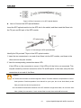
3.2.2 DIN-Rail Dismounting
Step 1: As shown in the following figure, press the device downward and move the device in
direction 1 until the bottom of the device is detached from the DIN rail.
Step 2: Pull the device upward and move the device in direction 2 until the device is removed
from the DIN rail completely.
Figure 6 DIN Rail Dismounting

Connection
8Kyland Opal5G/Opal10G IM-EN-June 2016
4 Connection
4.1 10/100/1000Base-T(X) Ethernet Port
10/100/1000Base-T(X) Ethernet port is equipped with RJ45 connector. The port is
self-adaptive. It can automatically configure itself to work in 10M, 100M, or 1000M state, full
or half duplex mode. The port can also adapt to MDI or MDI-X connection automatically. You
can connect the port to a terminal or network device with a straight-through or cross-over
cable.
Pin Definition
Figure7RJ45Port
Table 3 Pin Definitions of 10/100Base-T(X) RJ45 Port
Pin MDI-X MDI
1 Transmit/Receive Data (TRD1+) Transmit/Receive Data (TRD0+)
2 Transmit/Receive Data (TRD1-) Transmit/Receive Data (TRD0-)
3 Transmit/Receive Data (TRD0+) Transmit/Receive Data (TRD1+)
4 Transmit/Receive Data (TRD3+) Transmit/Receive Data (TRD2+)
5 Transmit/Receive Data (TRD3-) Transmit/Receive Data (TRD2-)
6 Transmit/Receive Data (TRD0-) Transmit/Receive Data (TRD1-)
7 Transmit/Receive Data (TRD2+) Transmit/Receive Data (TRD3+)
8 Transmit/Receive Data (TRD2-) Transmit/Receive Data (TRD3-)
Note:
"+" and "-" indicate level polarities.

Connection
9Kyland Opal5G/Opal10G IM-EN-June 2016
Wiring Sequence
Figure 8 Connection Using Straight-through/Cross-over Cable
Note:
The color of the cable for RJ45 connector meets the 568B standard: 1-orange and white,
2-orange, 3-green and white, 4-blue, 5-blue and white, 6-green, 7-brown and white, and
8-brown.
4.2 1000Base-X SFP slot
1000Base-X SFP slot (gigabit SFP slot) requires an gigabit SFP optical module to enable
data transmission.
Gigabit SFP Optical Module
Figure 9 Gigabit SFP Optical Module
An SFP optical module is equipped with LC connector, and each port consists of a TX
(transmit) port and an RX (receive) port. To enable communication between Device A and
Device B, connect the TX port of Device A to the RX port of Device B, and the RX port of
Device A to the TX port of Device B, as shown in the following figure.

Connection
10 Kyland Opal5G/Opal10G IM-EN-June 2016
Figure 10 Fiber Connection of an SFP Optical Module
How to Connect the SFP Optical Module
Insert the SFP optical module into the SFP slot in the switch, and then insert the fibers into
the TX port and RX port of the SFP module.
Figure 11 Connecting the SFP Optical Module
Identify the RX port and TX port of an SFP optical module:
1. Insert the two connectors in one end of two fibers into the SFP module, and those in the
other end into the peer module.
2. View the corresponding connection status LED:
If the LED is on, the connection is correct. If the LED is off, the link is not connected. This
may be caused by incorrect connection of the TX and RX ports. In this case, swop the two
connectors at one end of the fibers.
Caution:
The device uses laser to transmit signals in fibers. The laser meets the requirements of level 1
laser products. Routine operation is not harmful to your eyes, but do not look directly at the
fiber port when the device is powered on.
If the defined transmission distance of an SFP module is longer than 60km, do not use a short
fiber (<20km) for connection. If such a short fiber is used, the module will be burned.

Connection
11 Kyland Opal5G/Opal10G IM-EN-June 2016
4.3 Grounding
Grounding protects the device from lightning and interference. Therefore, you must ground
the device properly. You need to ground the device before it is powered on and disconnect
the grounding cable after the device is powered off.
There is a grounding screw (see Figure 2) on the top panel of the switch. The screw is for
chassis grounding. After crimping one end of the grounding cable to a cold pressed terminal,
secure the end of the grounding cable to the grounding screw and firmly connect the other
end to ground.
Note:
Cross-sectional area of the chassis grounding cable>2.5mm2; Grounding resistance<5.
4.4 Power Terminal Block
There is a power terminal block on the top panel of the device. You need to connect the
power wires to the terminal block to provide power for the device. The switch supports
redundant power supply with 4-pin 5.08mm-spacing plug-in terminal block. When one power
input is faulty, the switch can continue operating properly, thereby improving network
reliability
Note:
Use copper conductors only, temperature rating 85.5℃only.
All field wiring intended for connection to the power terminal shall consist of copper
conductors with the insulation locally removed. Additional intermediate connecting parts,
other than ferrules, shall not be used.
The exposed power cable wires connecting the plug-in terminal block should be 3-5mm
approximately.
4-Pin 5.08mm-Spacing Plug-in Terminal Block
Figure 12 4-Pin 5.08mm-Spacing Plug-in Terminal Block (socket)

Connection
12 Kyland Opal5G/Opal10G IM-EN-June 2016
Table 4 Pin Definitions of 4-Pin 5.08mm-Spacing Plug-in Terminal Block
Pin Number DC Wiring Definition AC Wiring Definition
1 PWR1: - PWR1: N
2 PWR1: + PWR1: L
3 PWR2: - PWR2: N
4 PWR2: + PWR2: L
Wiring and Mounting
Step 1: Ground the device properly according to section 4.3.
Step 2: Remove the power terminal block from the device.
Step 3: Insert the power wires into the power terminal block according to Table 4 and secure
the wires.
Step 4: Insert the terminal block with the connected wires into the terminal block socket on
the device.
Step 5: Connect one end of the power cable to an external power supply system (with the
allowed power range). If the power LED on the front panel of the switch turns on, the
power supply is connected properly.
Wiring and mounting should meet following specifications.
Table 5 Wiring and Mounting Specifications
Terminal Type Required Torque Wire Range (AWG)
Terminal Block Plug 4.5-5.0 lb-in 12-24
Caution:
Provision shall be made to prevent the rated voltage from being exceeded by transient
disturbances of more than 140% of the rated voltage.
Power adapter provide by end customer shall be non-sparking.
Before connecting the device to power supply, make sure that the power input meets the
power requirement. If connected to an incorrect power input, the device may be damaged.
To comply with UL restrictions, this equipment must be powered from a source compliant
with SELV.

Connection
13 Kyland Opal5G/Opal10G IM-EN-June 2016
Warning:
Do not touch any exposed conducting wire, terminal, or component with a voltage warning
sign, because it may cause personal injury.
Do not remove any part or plug in or out any connector when the device is powered on.
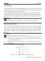
4.5 DIP Switches
There are two DIP switches on the top panel of the device, each switch has ON and OFF
states, and the default state is OFF. The function of the DIP switches is shown in the
following table.
Figure 13 DIP Switches
Table 6 Description of the DIP Switches
DIP Switches State Description
Ⅰ
ON Enable broadcast storm protection
OFF Disable broadcast storm protection
Ⅱ
ON Transmit Jumbo frame.
OFF Drop Jumbo frame.
Note:
The length of Jumbo frame is 1518~10240 bytes for Opal5G; and that is 1518~9600 bytes for
Opal10G.

LEDs
14 Kyland Opal5G/Opal10G IM-EN-June 2016
5LEDs
Table 7 LEDs
LED State Description
Power 1 LED
On The power 1 is connected and operates properly.
Off The power 1 is not connected or operates abnormally.
Power 2 LED
On The power 2 is connected and operates properly.
Off The power 2 is not connected or operates abnormally.
10/100/1000Base-T(X) Ethernet port
speed LED (yellow)
On 1000M working state (1000Base-TX)
Off
10/100M working state (10/100Base-T(X)) or no
connection
10/100/1000Base-T(X) Ethernet port
connection status LED (green)
On Effective port connection
Blinking Ongoing network activities
Off No effective port connection
LED 1 and LED 2 indicate the status of the left gigabit SFP slot, while LED 3 and LED 4 indicate the status
of the right gigabit SFP slot.
1000Base-X SFP slot speed LED
(yellow)
On 1000M working state (1000Base-X)
Off 100M working state (100Base-FX) or no connection
1000Base-X SFP slot connection
status LED (green)
On Effective port connection
Blinking Ongoing network activities
Off No effective port connection

Basic Features and Specifications
15 Kyland Opal5G/Opal10G IM-EN-June 2016
6 Basic Features and Specifications
Power Supply
Power Identifier Range
LV 24VAC/DC(18-30VAC, 50/60Hz; 12-48VDC)
Terminal Block 4-Pin 5.08mm-Spacing Plug-in Terminal Block
Rated Power Consumption
Rated Power Consumption Opal5G: 4.5W (MAX)
Opal10G: 10W (MAX)
Physical Characteristics
Housing Metal, fanless
Protection Class IP30
Installation DIN-Rail Mounting
Dimensions(W×H×D)
Opal5G: 29.6mm×114.5mm×68mm
Opal10G: 53.6mm×134mm×106mm
(excluding connectors, DIN rail)
Weight: Opal5G: 0.3Kg
Opal10G: 0.5Kg
Environmental Limits
Ambient Temperature
-10℃≤Tamb ≤60℃Opal5G-E, Opal10G-E series
-40℃≤Tamb ≤75℃Opal5G, Opal10G series
Storage Temperature -40℃~+85℃
Ambient Relative Humidity 5%~95% (no condensing)
Pollution degree 2
Altitude 2000m
MTBF
MTBF Opal5G:3241152h
Opal10G:2497305h
Warranty
Warranty Five years

Certificates Used for Compliance
16 Kyland Opal5G/Opal10G IM-EN-June 2016
7 Certificates Used for Compliance
Certificates Approvals
EMC CE,
FCC 47CFR Part2 and part15 Class A
Safety UL508/UL61010, Class1 Div2,
ATEX/IECEx
La page est en cours de chargement...
La page est en cours de chargement...
-
 1
1
-
 2
2
-
 3
3
-
 4
4
-
 5
5
-
 6
6
-
 7
7
-
 8
8
-
 9
9
-
 10
10
-
 11
11
-
 12
12
-
 13
13
-
 14
14
-
 15
15
-
 16
16
-
 17
17
-
 18
18
-
 19
19
-
 20
20
-
 21
21
-
 22
22


KYLAND Opal5G Guide d'installation
- Catégorie
- Commutateurs réseau
- Taper
- Guide d'installation
- Ce manuel convient également à
dans d''autres langues
- English: KYLAND Opal5G Installation guide
Autres documents
-
 ANTAIRA LMX-0702G-SFP-V2 Series Manuel utilisateur
-
Foundry Networks FES12GCF Guide d'installation
-
Leonton CEG2-0501-SFP Manuel utilisateur
-
-
-
-
-
 ANTAIRA LNX-1002G-10G-SFP Manuel utilisateur
-
-

