
®
Centrifugal Roof Supply Air Fan 1
®
Document 468410
Model SAF
Centrifugal Roof Supply Air Fan
Installation, Operation and Maintenance Manual
Please read and save these instructions for future reference. Read carefully before attempting to assemble, install,
operate or maintain the product described. Protect yourself and others by observing all safety information. Failure
to comply with these instructions will result in voiding of the product warranty and may result in personal injury
and/or property damage.
Only qualified personnel should install this fan.
Personnel should have a clear understanding of these
instructions and should be aware of general safety
precautions. Improper installation can result in electric
shock, possible injury due to coming in contact with
moving parts, as well as other potential hazards. Other
considerations may be required if high winds or seismic
activity is present. If more information is needed,
contact a licensed professional engineer before moving
forward.
1. Follow all local electrical and safety codes, as well as
the National Electrical Code (NEC) and the National
Fire Protection Agency (NFPA), where applicable.
Follow the Canadian Electric Code (CEC) in Canada.
2. The rotation of the wheel is critical. It must be free
to rotate without striking or rubbing any stationary
objects.
3. Motor must be securely and adequately grounded.
4. Do not spin fan wheel faster than max cataloged fan
RPM. Adjustments to fan speed significantly affects
motor load. If the fan RPM is changed, the motor
current should be checked to make sure it is not
exceeding the motor nameplate amps.
5. Do not allow the power cable to kink or come in
contact with oil, grease, hot surfaces or chemicals.
Replace cord immediately if damaged.
6. Verify that the power source is compatible with the
equipment.
7. Never open access doors to a duct while the fan is
running.
General Safety Information
DANGER
Always disconnect, lock and tag power source before
installing or servicing. Failure to disconnect power
source can result in fire, shock or serious injury.
CAUTION
When servicing the fan, motor may be hot enough
to cause pain or injury. Allow motor to cool before
servicing.
CAUTION
Precaution should be taken in explosive atmospheres.
DANGER
Pour écarter les risques d’incendie, de choc électrique
ou de blessure grave, veiller à toujours débrancher,
verrouiller et étiqueter la source de courant avant
l’installation ou l’entretien.
ATTENTION
Lors de toute intervention sur la soufflante, le moteur
peut être suffisamment chaud pour provoquer une
douleur voire une blessure. Laisser le moteur refroidir
avant toute maintenance.
ATTENTION
Faire preuve de précaution dans les atmosphères
explosives.
Centrifugal Roof Supply Air Fan
This roof mounted supply fan is designed to provide
non-tempered, filtered make-up air. Belt drive fans
are available in five sizes and include washable
aluminum filters.

Centrifugal Roof Supply Air Fan2
®
Receiving
Upon receiving the product check to ensure all items
are accounted for by referencing the delivery receipt
or packing list. Inspect each crate or carton for
shipping damage before accepting delivery. Alert the
carrier of any damage detected. The customer will
make a notation of damage (or shortage of items) on
the delivery receipt and all copies of the bill of lading
which is countersigned by the delivering carrier. If
damaged, immediately contact your representative. Any
physical damage to the unit after acceptance is not the
responsibility of the manufacturer.
Unpacking
Verify that all required parts and the correct quantity
of each item have been received. If any items are
missing, report shortages to your local representative to
arrange for obtaining missing parts. Sometimes it is not
possible that all items for the unit be shipped together
due to availability of transportation and truck space.
Confirmation of shipment(s) must be limited to only
items on the bill of lading.
Installation
Roof Mounting
NOTE: Refer to motor nameplate for wiring procedures.
Refer to switch manufacturer for installation and wiring
procedures.
1. Cut an appropriate sized hole in the roof surface.
Follow curb manufacturer’s installation instructions.
Caulk and flash curb to ensure a water tight seal.
2. Position curb on the roof.
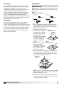
3. Good duct practices should
be followed in accordance
with SMACNA and AMCA
guidelines, NFPA 96 and
any local codes. The
ductwork should extend far
enough above the roofline
to meet the supply unit
once it is installed. See
Figure 2.
4. Before installing supply
unit, apply a sealant
around the perimeter of
the supply duct to isolate
the fan and minimize
vibration. See Figure 3.
5. Use a crane and set of spreader bars hooked to the
factory lifting holes (see Figure 4) to lift and center
the unit on the curb. Use self-tapping sheet metal
screws to fasten unit to the curb.
NOTE: The use of all lifting holes and set of spreader
bars is mandatory when lifting unit.
Always use all four
lifting holes when using a sling.
6. For unassembled units, or when motor and drive is
shipped loose, install the motor and drive package
as shown in Figures 5, 6 and 7.
MOTOR
L1
115/208-230/60/1
J-BOX
SUPPLY VOLTAGE
L2
208-230/460/60/3
MOTOR
J-BOX
SUPPLY VOLTAGE
L1
L2
L3
Figure 1 -
Connection Wiring Diagram
Supply
Ductwork
by Others
Figure 2 -
Installing Ductwork
Sealant
Ductwork with duct
adapter installed
Figure 3 -
Applying Sealant
Lifting
Hole (x4)
Spreader Bars
Figure 4 -
Lifting Unit

Centrifugal Roof Supply Air Fan 3
®
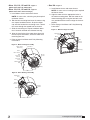
• Sizes 110, 112, 115 and 118 - Figure 5
(Motor Frame Sizes 56 and Smaller)
• Sizes 110, 112, 115 and 118 - Figure 6
(Motor Frame Sizes 143T and Larger)
a. Install blower sheave and motor sheave.
NOTE: On some units, a bushing may be required
on blower sheave.
b. Bolt the belt tensioning bracket to the motor using
one square head bolt and nut. Snap the rubber
cap onto the head of the tensioning screw. Thread
the screw through the tapped hole on the belt.
c. Slide the remaining two square head bolts down
the U-channel attached to the blower housing.
d. Align the slots/holes of the motor base plate with
the two square head bolts, attach the motor with
remaining two nuts.
e. Refer to page 4 for Motor and Pulley Mounting
instructions.
• Size 120 - Figure 7
a. Install blower sheave and motor sheave.
NOTE: On some units a bushing may be required
on blower sheave.
b. Align the motor with the appropriate holes in
the motor mounting plate. Bolt the motor to the
motor mounting plate using the four bolts and
nuts provided. Make certain to align the sheaves
properly.
c. Refer to page 4 for Motor and Pulley Mounting
instructions.
Belt
Bushing
Motor
Motor
Sheave
Blower
Sheave
Adjustment
Slots
Figure 6 - Drive Package Assembly
Motor
Sheave
Adjustment
Slots
Motor
Belt
Blower
Sheave
Bushing
Figure 7 - Drive Package Assembly
Blower
Sheave
Belt
Bushing
U-Channel
Motor Sheave
Square Head
Bolt/nut (2)
Motor
Tensioning
Screw
Rubber Cap
Belt
Tensioning
Bracket
Figure 5 - Drive Package Assembly

Centrifugal Roof Supply Air Fan4
®
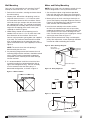
Wall Mounting
Only size 110 is designed for wall mounting. Do NOT
attempt to wall mount sizes 112, 115, 118 or 120.
1. Refer to the instructions, warnings and notes found
for roof mounting.
2. Masonry Wall. Around the wall opening, install an
angle iron frame at least 2 x 2 x 1/4 inch to match
the inside base dimension of the ventilator. Secure
with lead cinch type anchors with non-ferrous bolts,
not supplied (3 per side). The ventilator should then
be mounted (inlet assembly down) to the mounting
angle with self-tapping sheet metal screws (not
supplied) as shown in Figure 8.
3. Wood Siding. Around the wall opening install a
wooden frame at least 2 x 4 in. to match the inside
base dimension of the ventilator. Secure with
counter-sunk expansion type lag bolts (not supplied,
3 per side). The ventilator should then be mounted
(inlet assembly down) to the mounting frame with
square head wood screws (not supplied) as shown in
Figure 8.
NOTE: The actual size of the wall opening is
determined by the duct size.
4. Any mounting flange connection between the wall,
mounting flange and the ventilator, should be coated
with a suitable caulking compound or approved
waterproof mastic sealer to prevent water leakage
into the ventilator.
5. It is recommended to install the unit with the inlet
assembly installed in a horizontal position (left or
right install configuration only). The inlet assembly
must be rotated so that the filters point in a
downward configuration, as shown in Figure 8.
Motor and Pulley Mounting
NOTE: For UL listed units, the motor used with this fan
must be designated as such by the Manufacturer.
1. Secure motor to plate using hardware provided.
Holes will align when the motor frame (shaft end) is
flush with the edge of the motor plate. See Figure 9.
2. Mount pulleys on shafts securing to shaft with set
screw. Check pulleys for proper alignment. Refer to
Figure 10. Misaligned pulleys lead to excessive belt
wear, vibration, noise and blower loss.
3. Install the belt and adjust the tension to allow
for 1/64 inch of deflection per inch of span when
moderate thumb pressure is applied to the belt. Too
much tension will cause excess bearing wear and
noise. Too little tension will cause slippage at startup
and uneven wear. Refer to Figure 11.
4. Adjust RPM to desired level using a variable pitch
pulley. After adjustment, motor amperage should be
checked to avoid overloading of the motor.
Deflection (in.) =
Belt Span (in.)
62.5 (in.)
Belt Span
Figure 11 - Belt Tension
Motor plate
Setscrew
Shaft Pulley
Fixed Pitch
Type.
Motor Pulley
Variable Pitch Type
Figure 9 - Drive Package Diagram
WRONG
CORRECT
WRONG
Figure 10 - Pulley Alignment
Figure 8 - Wall Installation

Centrifugal Roof Supply Air Fan 5
®
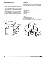
Assemble Weatherhood
NOTE: Assembly requires a 3/8 inch nut runner.
1. Remove top cover.
2. Carefully remove weatherhood assembly and filters
from inside unit.
3. Slide weatherhood into place as shown in Figure 12.
Weatherhood flange should be on the inside of the
unit.
4. Attach weatherhood by using 3/8 inch nut runner.
Drive the provided 1/4 inch thread rolling screws
through the side panel and into the weatherhood.
5. Loosen the thumb screws on the filter racks. Install
filters. Be sure the filters are properly oriented (airflow
directions are located on the side of the filter). Slide
filter rack back into place and tighten thumb screws.
6. Reinstall top cover.
Figure 12 - Weatherhood Assembly
1. Blower Assembly
2. Bearing(s)
3. Aluminum Filter(s)
4. Top Panel
5. Side Panel
6. Back Panel
7. Base
8. Weatherhood Assembly
One filter is required for size 110
Two filters are required for sizes 112, 115, 118 and 120
4
8
3
7
2
1
5
6
Parts List
Each fan bears a manufacturer’s nameplate with model
number and serial number embossed. This information
will assist the local representative and the factory in
providing service and replacement parts. Before taking
any corrective action, make certain unit is not capable
of operation during repairs.

Centrifugal Roof Supply Air Fan6
®
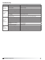
Troubleshooting
PROBLEM CAUSE CORRECTIVE ACTION
Ventilator
Inoperative
Blown fuse or breaker Replace or repair
Defective motor Replace or repair
Incorrectly wired Shut power OFF and check wiring for proper connections
Broken belts Replace
Insufficient
Airflow
Blocked duct or clogged filters Clean or replace
Speed too slow Check for correct drives
Damper closed Inspect/repair damper
Belt slippage Replace/adjust tension
Loose fitting duct sections
permitting air loss
Check for secure connection where duct sections are joined
(suggest duct tape at seams for sealed closure)
Excessive
Noise
or Vibration
Belt(s) too loose/tight Adjust tension
Loose or defective bearings Replace bearings
Loose wheel or sheaves Tighten set screws
Accumulation of material on wheel Clean
Misaligned sheaves Realign
Ventilator base not securely
anchored
Secure properly
Fan wheel out of balance Replace wheel
Motor
Overloads
or Overheats
Wheel RPM too high Check drives
Shorted motor winding Replace motor
Incorrect wheel rotation Check motor wiring
Over/Under line voltage Contact Power Company
Belt slippage Tighten belt

Centrifugal Roof Supply Air Fan 7
®
Maintenance Log
Date ___________________Time _____________ AM/PM
Notes: ___________________________________________
_________________________________________________
_________________________________________________
_________________________________________________
_________________________________________________
Date ___________________Time _____________ AM/PM
Notes: ___________________________________________
_________________________________________________
_________________________________________________
_________________________________________________
_________________________________________________
Date ___________________Time _____________ AM/PM
Notes: ___________________________________________
_________________________________________________
_________________________________________________
_________________________________________________
_________________________________________________
Date ___________________Time _____________ AM/PM
Notes: ___________________________________________
_________________________________________________
_________________________________________________
_________________________________________________
_________________________________________________
Date ___________________Time _____________ AM/PM
Notes: ___________________________________________
_________________________________________________
_________________________________________________
_________________________________________________
_________________________________________________
Date ___________________Time _____________ AM/PM
Notes: ___________________________________________
_________________________________________________
_________________________________________________
_________________________________________________
_________________________________________________
Date ___________________Time _____________ AM/PM
Notes: ___________________________________________
_________________________________________________
_________________________________________________
_________________________________________________
_________________________________________________
Date ___________________Time _____________ AM/PM
Notes: ___________________________________________
_________________________________________________
_________________________________________________
_________________________________________________
_________________________________________________
Date ___________________Time _____________ AM/PM
Notes: ___________________________________________
_________________________________________________
_________________________________________________
_________________________________________________
_________________________________________________
Date ___________________Time _____________ AM/PM
Notes: ___________________________________________
_________________________________________________
_________________________________________________
_________________________________________________
_________________________________________________
Date ___________________Time _____________ AM/PM
Notes: ___________________________________________
_________________________________________________
_________________________________________________
_________________________________________________
_________________________________________________
Date ___________________Time _____________ AM/PM
Notes: ___________________________________________
_________________________________________________
_________________________________________________
_________________________________________________
_________________________________________________

468410 • SAF, Rev. 3, June 2018 Copyright 2018 © Greenheck Fan Corporation8
As a result of our commitment to continuous improvement, Greenheck reserves the right to change specifications
without notice.
Specific Greenheck product warranties are located on greenheck.com within the product area tabs and in the
Library under Warranties.
®
Phone: 715.359.6171 • Fax: 715.355.2399 • Parts: 800.355.5354 • E-mail: [email protected] • Website: www.greenheck.com
Our Commitment
AMCA Publication 410-96, Safety Practices for Users and
Installers of Industrial and Commercial Fans, provides
additional safety information. This publication can be obtained
from AMCA International, Inc. at www.amca.org.
Greenheck’s Centrifugal Roof Supply Fan, Model SAF
catalog provides additional information describing the
equipment, fan performance, available accessories, and
specification data.
-
 1
1
-
 2
2
-
 3
3
-
 4
4
-
 5
5
-
 6
6
-
 7
7
-
 8
8


dans d''autres langues
Documents connexes
Autres documents
-
Unbranded R6GP 6, 7.5 - 10 Ton Archived 2/23/12 Guide d'installation
-
Unbranded R6GN 12.5 - 15 Ton Guide d'installation
-
-
Canarm ALX180-DD Operation Instructions Manual
-
Unbranded P7TQ Guide d'installation
-
-
Unbranded R7TQ Guide d'installation
-
-
 Hadar Lighting I-HDL106-07--IOM Crane Damper Bracket Guide d'installation
