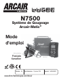
Arcair N7500 Gouging System Manuel utilisateur
- Catégorie
- Système de soudage
- Taper
- Manuel utilisateur
Ce manuel convient également à

English
Français
Canadien
Revision: AG Issue Date: Jan. 1, 2015 Manual No.: 89250890
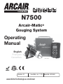
Arcair-Matic
®
Gouging System
N7500
Operating
Manual
www.VictorTechnologies.com/Arcair

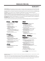
WE APPRECIATE YOUR BUSINESS!
Congratulations on receiving your new Arcair
®
product. We are proud to have you as our customer and will
strive to provide you with the best service and support in the industry. This product is backed by our extensive
warranty and world-wide service network.
We know you take pride in your work and we feel privileged to provide you with this high performance
product that will help you get the job done.
For more than 60 years Arcair has provided quality products you can trust, when your reputation is on the
line.
YOU ARE IN GOOD COMPANY!
ARCAIR, an ESAB Brand is a manufacturer of cutting & metal removal products. We distinguish ourselves from
our competition through market-leading innovation and truly dependable products that will stand the test of
time.
We strive to enhance your productivity, efficiency and welding performance, enabling you to excel in your
craft. We design products with the welder in mind delivering- advanced features, durability, ease of use and
ergonomic comfort.
Above all, we are committed to a safer working environment within the welding industry. Your satisfaction
with this product and its safe operation is our ultimate concern. Please take the time to read the entire
manual, especially the Safety Precautions.
If you have any questions or concerns regarding your new Arcair product, please contact our friendly and
knowledgeable Customer Service Team at:
1-800-462-2782 (USA) and 1-905-827-4515 (Canada),
or visit us on the web at www.victortechnologies.com/arcair

WARNINGS
Read and understand this entire Manual and your employer’s safety practices before installing,
operating, or servicing the equipment.
While the information contained in this Manual represents the Manufacturer's best judgement, the
Manufacturer assumes no liability for its use.
Arcair-Matic
®
N7500 Gouging System
Operating Manual
Operating Manual Guide Number: 89250890
Published by:
ESAB 940-566-2000
2800 Airport Rd. www.victortechnologies.com/arcair
Denton, TX. 76208 U.S. Customer Care: 800-426-1888
International Customer Care: 905-827-9777
Copyright © 2012, 2013, 2015 ESAB Welding and Cutting Products All rights reserved.
Reproduction of this work, in whole or in part, without written permission of the publisher is
prohibited.
The publisher does not assume and hereby disclaims any liability to any party for any loss or dam-
age caused by any error or omission in this Manual, whether such error results from negligence,
accident, or any other cause.
Publication Date: January, 2012
Revision Date: January 1, 2015
Patent Pending
Record the following information for Warranty purposes:
Where Purchased:
Purchase Date:
Part Number Serial Number
Control Box: ______________________ ________________________
Pendant: ______________________ ________________________
Torch Head: ______________________ ________________________

TABLE OF CONTENTS
SECTION 1:
GENERAL INFORMATION ........................................................................... 1-1
1.01 Notes, Cautions and Warnings ........................................................................ 1-1
1.02 Arc Welding Hazards ....................................................................................... 1-1
1.03 Principal Safety Standard Publications ........................................................... 1-4
1.04 Declaration of Conformity ............................................................................... 1-5
SECTION 2:
SPECIFICATIONS ..................................................................................... 2-1
2.01 Arcair-Matic N7500 Gouging System .............................................................. 2-1
2.02 N7500 Specifications ...................................................................................... 2-2
SECTION 3:
SYSTEM COMPONENT DESCRIPTION ............................................................ 3-1
3.01 Control Box ..................................................................................................... 3-1
3.02 Torch Head ...................................................................................................... 3-4
3.03 Remote Pendant ............................................................................................. 3-6
3.04 Electrodes ....................................................................................................... 3-7
3.05 Gouging Operation Settings ............................................................................ 3-8
3.06 Selecting the Proper Electrode Diameter ........................................................ 3-9
3.07 Keeping Electrodes Dry ................................................................................... 3-9
3.08 Secondary Power Cables (Welding Leads) ..................................................... 3-9
3.09 Compressed Air ............................................................................................ 3-10
3.10 Main Air Line ................................................................................................ 3-10
SECTION 4:
ASSEMBLY AND INSTALLATION ................................................................... 4-1
4.01 Receiving and Handling .................................................................................. 4-1
4.02 Assembly ........................................................................................................ 4-3
4.03 Miscellaneous Cable/Plumbing Assemblies .................................................... 4-3
4.04 Control Box Installation .................................................................................. 4-4
4.05 Torch Head Installation ................................................................................... 4-7
4.06 Remote Pendant Installation ........................................................................... 4-8
4.07 Remote Pendant Storage ................................................................................ 4-9
SECTION 5: OPERATING THE N7500 SYSTEM .......................................................... 5-1
5.01 Remote Pendant Operation ............................................................................. 5-1
5.02 Position Torch Head ........................................................................................ 5-2
5.03 Insert the Electrode ......................................................................................... 5-2
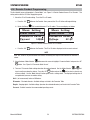
5.04 Remote Pendant Programming ...................................................................... 5-3

TABLE OF CONTENTS
SECTION 6:
N7500 SYSTEM USES ............................................................................... 6-1
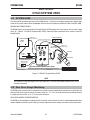
6.01 SYSTEM USES ................................................................................................ 6-1
6.02 Zero Force Rough Machining .......................................................................... 6-1
SECTION 7:
MAINTENANCE ....................................................................................... 7-1
7.01 Introduction .................................................................................................... 7-1
7.02 Remote Pendant ARCTIME ............................................................................. 7-2
SECTION 8:
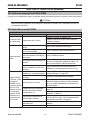
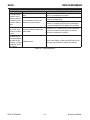
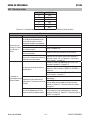
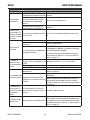
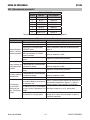
TROUBLESHOOTING GUIDE ........................................................................ 8-1
8.01 Arcair-Matic N7500 Gouging System .............................................................. 8-1
8.02 N7500 General ................................................................................................ 8-1
8.03 Torch Head ...................................................................................................... 8-2
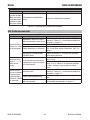
8.04 Remote Pendant ............................................................................................. 8-4
8.05 Control Box ..................................................................................................... 8-5
SECTION 9:
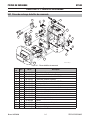
REPLACEMENT PARTS .............................................................................. 9-1
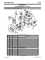
9.01 Control Box Replacement Parts ...................................................................... 9-1
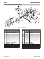
9.02 Torch Head Replacement Parts ....................................................................... 9-2
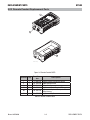
9.03 Remote Pendant Replacement Parts ............................................................... 9-3
9.04 110V Power Supply Cable Assembly .............................................................. 9-4
9.05 220V Power Supply Cable Assembly .............................................................. 9-4
9.06 Pendant Cable Assembly ................................................................................ 9-4
9.07 Motor Cable Assembly .................................................................................... 9-4
9.08 Power Supply Communication Cable Assembly .............................................. 9-4
9.09 Power Cables .................................................................................................. 9-4
9.10 Air Hose Assembly .......................................................................................... 9-4
SECTION 10:
APPENDIX ............................................................................................. A-1
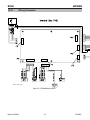
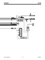
10.01 Wiring Schematic .......................................................................................... A-2
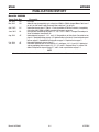
PUBLICATION HISTORY ................................................................................... A-4
Statement of Warranty .......................................................................................1

FIGURES AND TABLES
SECTION 2:
SPECIFICATIONS ..................................................................................... 2-1
Table 2-1: N7500 Specifications .............................................................................. 2-2
SECTION 3:
SYSTEM COMPONENT DESCRIPTION ............................................................ 3-1
Figure 3-1: Control Box ........................................................................................... 3-1
Table 3-2: Control Box Features .............................................................................. 3-2
Figure 3-3: LEFT Side of Control Box ...................................................................... 3-3
Figure 3-4: RIGHT Side of Control Box ................................................................... 3-3
Figure 3-5: BACK of Control Box ............................................................................. 3-3
Figure 3-6: Torch Head ............................................................................................ 3-4
Figure 3-7: Torch Head Components ....................................................................... 3-4
Table 3-8: Torch Head Features ............................................................................... 3-5
Figure 3-9: Remote Pendant ................................................................................... 3-6
Table 3-10: Remote Pendant Controls ..................................................................... 3-6
Chart 3-11: Electrode Selection ............................................................................... 3-7
Table 3-12: Operating Parameters ........................................................................... 3-8
Table 3-13: Power Cable Requirements .................................................................. 3-9
Table 3-14: Compressed Air Input Requirements .................................................. 3-10
SECTION 4:
ASSEMBLY AND INSTALLATION ................................................................... 4-1
Figure 4-1: Control Box .......................................................................................... 4-1
Figure 4-2: Torch Head ............................................................................................ 4-1
Figure 4-3: Remote Pendant ................................................................................... 4-1
Figure 4-4: Control Box Nameplate ......................................................................... 4-2
Figure 4-5: Remote Pendant and Torch Head Nameplates ...................................... 4-2
Figure 4-6: Nameplate Locations ............................................................................ 4-2
Table 4-7: Cable Identification ................................................................................. 4-3
Figure 4-8: Assembly Stage 1 ................................................................................. 4-4
Figure 4-9: Power Supply Comm. Cable Pin Configuration ..................................... 4-5
Table 4-10: Standard Wiring Connections ............................................................... 4-6
Figure 4-11: Assembly Stage 2 ............................................................................... 4-7
Figure 4-12: Assembly Stage 3 ............................................................................... 4-8
Figure 4-13: Pendant Mounting .............................................................................. 4-9
Figure 4-14: Pendant Mounted ................................................................................ 4-9

SECTION 5: OPERATING THE N7500 SYSTEM .......................................................... 5-1
Figure 5-1: Remote Pendant ................................................................................... 5-1
Table 5-2: Remote Pendant Controls ....................................................................... 5-1
Figure 5-3: Torch Head Parts .................................................................................. 5-2
Figure 5-4: Default Pendant Screen CC or CV mode ............................................... 5-3
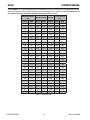
Table 5-5: Parameter Table ...................................................................................... 5-4
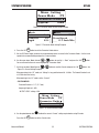
Figure 5-6: Parameter Guide Screen (using CV mode) ............................................ 5-5
Figure 5-7: Parameter Guide Setting Examples ....................................................... 5-5
Figure 5-8: Current Setting Example ....................................................................... 5-5
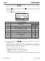
Figure 5-9: Travel Delay Screen ............................................................................... 5-6
Table 5-10: Travel Delay Setting .............................................................................. 5-6
Figure 5-11: No Current Detect screens .................................................................. 5-7
SECTION 6:
N7500 SYSTEM USES ............................................................................... 6-1
Figure 6-1: N7500 DC Straight Polarity (DCEN) ...................................................... 6-1
SECTION 7:
MAINTENANCE ....................................................................................... 7-1
Figure 7-1: Maintenance ......................................................................................... 7-1
Figure 7-2: Arctime Screen ..................................................................................... 7-2
SECTION 8:
TROUBLESHOOTING GUIDE ........................................................................ 8-1
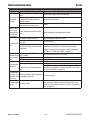
Table 8-1: General Troubleshooting ......................................................................... 8-2
Table 8-2: Torch Head Motor 6 PIN Wire Schedule ................................................. 8-2
Table 8-3: Torch Head Troubleshooting ................................................................... 8-3
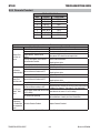
Table 8-4: Pendant Cable Pin Identification ............................................................. 8-4
Table 8-5: Remote Pendant Troubleshooting .......................................................... 8-4
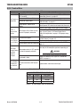
Table 8-6: Control Box Troubleshooting .................................................................. 8-5
Table 8-7: AC Power Supply Cable Pin Identification............................................... 8-5
SECTION 9:
REPLACEMENT PARTS .............................................................................. 9-1
Figure 9-1: Control Box PARTS ............................................................................... 9-1
Table 9-2: Control Box PARTS ................................................................................. 9-1
Figure 9-3: Torch Head PARTS ................................................................................ 9-2
Table 9-4: Torch Head PARTS ................................................................................. 9-2
Figure 9-5: Remote Pendant PARTS ....................................................................... 9-3
Table 9-6: Remote Pendant PARTS ......................................................................... 9-3
SECTION 10:
APPENDIX ............................................................................................. A-1
Figure 10-1: N7500 Wiring Schematic .................................................................... A-3

This Page Intentionally Blank

GENERAL INFORMATION N7500
Manual 89250890 1-1 GENERAL INFORMATION
SECTION 1:
GENERAL INFORMATION
1.01 Notes, Cautions and Warnings
WARNING
PROTECT YOURSELF AND OTHERS FROM POSSIBLE SERIOUS INJURY OR DEATH. KEEP
CHILDREN AWAY. PACEMAKER WEARERS KEEP AWAY UNTIL CONSULTING YOUR DOCTOR.
DO NOT LOSE THESE INSTRUCTIONS. READ OPERATING/INSTRUCTION MANUAL BEFORE
INSTALLING, OPERATING OR SERVICING THIS EQUIPMENT.
Welding products and welding processes can cause serious injury or death, or damage to other equipment or property, if the
operator does not strictly observe all safety rules and take precautionary actions.
Safe practices have developed from past experience in the use of welding and cutting. These practices must be learned
through study and training before using this equipment. Some of these practices apply to equipment connected to power
lines; other practices apply to engine driven equipment. Anyone not having extensive training in welding and cutting practices
should not attempt to weld.
Safe practices are outlined in the American National Standard Z49.1 entitled: SAFETY IN WELDING AND CUTTING. This publica-
tion and other guides to what you should learn before operating this equipment are listed at the end of these safety precau-
tions. HAVE ALL INSTALLATION, OPERATION, MAINTENANCE, AND REPAIR WORK PERFORMED
ONLY BY QUALIFIED PEOPLE.
WARNING
SERIOUS INJURY OR DEATH may result if welding and cutting equipment is not properly installed, used, and main-
tained. Misuse of this equipment and other unsafe practices can be hazardous. The operator, supervisor, and
helper must read and understand the following safety warnings and instructions before installing or using any
welding or cutting equipment, and be aware of the dangers of the welding or cutting process. Training and proper
supervision are important for a safe work place. Keep these instructions for future use. Additional recommended
safety and operating information is referenced in each section.
1. Do not touch live electrical parts.
2. Wear dry, hole-free insulating gloves and body protection.
3. Insulate yourself from work and ground using dry insulat-
ing mats or covers.
4. Disconnect input power or stop engine before installing
or servicing this equipment. Lock input power disconnect
switch open, or remove line fuses so power cannot be
turned on accidentally.
5. Properly install and ground this equipment according to
its Owner’s Manual and national, state, and local codes.
6. Turn off all equipment when not in use. Disconnect power
to equipment if it will be left unattended or out of service.
7. Use fully insulated electrode holders. Never dip holder in
water to cool it or lay it down on the ground or the work
surface. Do not touch holders connected to two welding
machines at the same time or touch other people with
the holder or electrode.
1.02 Arc Welding Hazards
WARNING
ELECTRIC SHOCK can kill.
Touching live electrical parts can cause fatal
shocks or severe burns. The electrode and work
circuit is electrically live whenever the output is
on. The input power circuit and machine internal
circuits are also live when power is on. In semi-
automatic or automatic wire welding, the wire,
wire reel, drive roll housing, and all metal parts
touching the welding wire are electrically live.
Incorrectly installed or improperly grounded
equipment is a hazard.

N7500 GENERAL INFORMATION
GENERAL INFORMATION 1-2 Manual 89250890
8. Do not use worn, damaged, undersized, or poorly spliced
cables.
9. Do not wrap cables around your body.
10. Ground the workpiece to a good electrical (earth) ground.
11. Do not touch electrode while in contact with the work
(ground) circuit.
12. Use only well-maintained equipment. Repair or replace
damaged parts at once.
13. In confined spaces or damp locations, do not use a welder
with AC output unless it is equipped with a voltage re-
ducer. Use equipment with DC output.
14. Wear a safety harness to prevent falling if working above
floor level.
15. Keep all panels and covers securely in place.
WARNING
ARC RAYS can burn eyes and skin; NOISE can
damage hearing. Arc rays from the welding
process produce intense heat and strong
ultraviolet rays that can burn eyes and skin. Noise
from some processes can damage hearing.
1. Wear a welding helmet fitted with a proper shade of filter
(see ANSI Z49.1 listed in Safety Standards) to protect your
face and eyes when welding or watching.
2. Wear approved safety glasses. Side shields recom-
mended.
3. Use protective screens or barriers to protect others from
flash and glare; warn others not to watch the arc.
4. Wear protective clothing made from durable, flame-
resistant material (wool and leather) and foot protection.
5. Use approved ear plugs or ear muffs if noise level is high.
WARNING
FUMES AND GASES can be hazardous to your
health.
Welding produces fumes and gases. Breathing
these fumes and gases can be hazardous to
your health.
1. Keep your head out of the fumes. Do not breath the fumes.
2. If inside, ventilate the area and/or use exhaust at the arc
to remove welding fumes and gases.
3. If ventilation is poor, use an approved air-supplied respira-
tor.
4. Read the Material Safety Data Sheets (MSDSs) and the
manufacturer’s instruction for metals, consumables, coat-
ings, and cleaners.
5. Work in a confined space only if it is well ventilated, or
while wearing an air-supplied respirator. Shielding gases
used for welding can displace air causing injury or death.
Be sure the breathing air is safe.
6. Do not weld in locations near degreasing, cleaning, or
spraying operations. The heat and rays of the arc can
react with vapors to form highly toxic and irritating gases.
7. Do not weld on coated metals, such as galvanized, lead,
or cadmium plated steel, unless the coating is removed
from the weld area, the area is well ventilated, and if
necessary, while wearing an air-supplied respirator. The
coatings and any metals containing these elements can
give off toxic fumes if welded.
WARNING
WELDING can cause fire or explosion.
Sparks and spatter fly off from the welding arc.
The flying sparks and hot metal, weld spatter, hot
workpiece, and hot equipment can cause fires
and burns. Accidental contact of electrode or
welding wire to metal objects can cause sparks,
overheating, or fire.
1. Protect yourself and others from flying sparks and hot
metal.
2. Do not weld where flying sparks can strike flammable
material.

GENERAL INFORMATION N7500
Manual 89250890 1-3 GENERAL INFORMATION
3. Remove all flammables within 35 ft. (10.7 m) of the welding
arc. If this is not possible, tightly cover them with approved
covers.
4. Be alert that welding sparks and hot materials from weld-
ing can easily go through small cracks and openings to
adjacent areas.
5. Watch for fire, and keep a fire extinguisher nearby.
6. Be aware that welding on a ceiling, floor, bulkhead, or
partition can cause fire on the hidden side.
7. Do not weld on closed containers such as tanks or drums.
8. Connect work cable to the work as close to the welding
area as practical to prevent welding current from traveling
long, possibly unknown paths and causing electric shock
and fire hazards.
9. Do not use welder to thaw frozen pipes.
10. Remove stick electrode from holder or cut off welding wire
at contact tip when not in use.
WARNING
FLYING SPARKS AND HOT METAL can cause injury.
Chipping and grinding cause flying metal. As welds
cool, they can throw off slag.
1. Wear approved face shield or safety goggles. Side shields
recommended.
2. Wear proper body protection to protect skin.
WARNING
MOVING PARTS can cause injury.
Moving parts, such as fans, rotors, and belts can cut fingers
and hands and catch loose clothing.
1. Keep all doors, panels, covers, and guards closed and
securely in place.
2. Stop engine before installing or connecting unit.
3. Have only qualified people remove guards or covers for
maintenance and troubleshooting as necessary.
4. To prevent accidental starting during servicing, disconnect
negative (-) battery cable from battery.
5. Keep hands, hair, loose clothing, and tools away from
moving parts.
6. Reinstall panels or guards and close doors when servicing
is finished and before starting engine.
NOTE
The following is a quotation from the General Conclusions
Section of the U.S. Congress, Office of Technology Assessment,
Biological Effects of Power Frequency Electric & Magnetic
Fields - Background Paper, OTA-BP-E-63 (Washington, DC:
U.S. Government Printing Office, May 1989): “...there is now a
very large volume of scientific findings based on experiments
at the cellular level and from studies with animals and people
which clearly establish that low frequency magnetic fields
interact with, and produce changes in, biological systems.
While most of this work is of very high quality, the results are
complex. Current scientific understanding does not yet allow
us to interpret the evidence in a single coherent framework.
Even more frustrating, it does not yet allow us to draw definite
conclusions about questions of possible risk or to offer clear
science-based advice on strategies to minimize or avoid
potential risks.”
To reduce magnetic fields in the workplace, use the following
procedures.
1. Keep cables close together by twisting or taping them.
2. Arrange cables to one side and away from the opera-
tor.
3. Do not coil or drape cable around the body.
4. Keep welding power source and cables as far away
from body as practical.
ABOUT PACEMAKERS:
The above procedures are among those also
normally recommended for pacemaker wearers.
Consult your doctor for complete information.

N7500 GENERAL INFORMATION
GENERAL INFORMATION 1-4 Manual 89250890
1.03 Principal Safety Standard
Publications
1. Code of Federal Regulations (OSHA) Sec-
tion 29, Part 1910.95, 132, 133, 134, 139,
251, 252, 253, 254, and 1000. U.S. Govern-
ment Printing Office, Washington, DC 20402
http://www.osha.gov/pls/oshaweb/owasrch.search_
form?p_doc_type=STANDARDS&p_toc_level=1&p_
keyvalue=1910
2. ANSI Z49.1 “Safety in Welding and Cutting”
http://www.nssn.org/
3. ANSI Z87.1 “Practice for Occupation-
al and Educational Eye and Face Protection”
http://www.nssn.org/
4. ANSI Z88.2. “Standard Practice for Respira-
tory Protection.” American National Standards
Institute, 1430 Broadway, New York, NY 10018
http://www.nssn.org/
5. AWS F4.1. “Recommended Safe Prac-
tices for Welding and Cutting Containers”
http://www.aws.org/w/a/technical/index.html
6. AWS C5.3. “Recommended Practices for Air
Carbon-Arc Gouging and Cutting.” The Amer-
ican Welding Society, 550 NW Lejeune Rd.,
P.O. Box 351040, Miami, FL 33135
http://www.aws.org/w/a/technical/index.html
7. NFPA 51B. “Fire Prevention in Cut-
ting and Welding Processes.”
http://www.nfpa.org/aboutthecodes/list_of_codes_
and_standards.asp
8. NFPA-7. “National Electrical Code” National Fire Pro-
tection Association, Battery Park, Quincy, MA 02269
http://www.nfpa.org/aboutthecodes/list_of_codes_
and_standards.asp
9. CSA W117.2. “Safety in Welding, Cutting and Allied
Processes”. Canadian Standards Association, 178
Rexdale Blvd., Rexdale, Ontario, Canada M9W 1R3
http://ccinfoweb.ccohs.ca/
10. ANSI Z535 Safety Alerting Standards
http://www.nssn.org/
11. Refer to your local codes.

GENERAL INFORMATION N7500
Manual 89250890 1-5 GENERAL INFORMATION
1.04 Declaration of Conformity
Manufacturer: Victor Technologies
Address: 2800 Airport Rd.
Denton, TX 76208
USA
Description of equipment: Gouging Equipment (GMAW, MMAW, GTAW, CAG and wirefeeders). Including, but not limited to
Arcair-Matic N7500 Gouging System and associated accessories.
Serial numbers are unique with each individual piece of equipment and details the description and parts that are used to
manufacture a unit and date of manufacture.
The equipment conforms to all applicable aspects and regulations of the ‘Low Voltage Directive’ (Directive 73/23/EU, as recently
changed in Directive 93/68/EU and to the National legislation for the enforcement of the Directive.
National Standard and Technical Specifications
The product is designed and manufactured to a number of standards and technical requirements among them are:
• AS1966-1 applicable to welding equipment and associated accessories.
• AS/NZS 3652-(EMC Directive EN50199) applicable to arc welding equipment - generic emissions and regulations.
• EN60974-1 applicable to welding equipment and associated accessories.
• AS60974.1 applicable to welding equipment and associated accessories.
• IEC 60974-1 applicable to welding equipment and associated accessories
• 2002/95/EC RoHS directive
Extensive product design verification is conducted at the manufacturing facility as part of the routine design and manufactur-
ing process, to ensure the product is safe and performs as specified. Rigorous testing is incorporated into the manufacturing
process to ensure the manufactured product meets or exceeds all design specifications.
Arcair has been manufacturing and merchandising an extensive equipment range with superior performance, ultra safe
operation and world class quality for years and will continue to achieve excellence.

N7500 GENERAL INFORMATION
GENERAL INFORMATION 1-6 Manual 89250890
This Page Intentionally Blank

Manual 89250890 2-1 SPECIFICATIONS
SPECIFICATIONS N7500
2.01 Arcair-Matic N7500 Gouging System
The Arcair-Matic N7500 Gouging System adds new dimensions of flexibility and control in modern weld preparation. It’s
the most advanced air carbon-arc gouging/grooving system in the world. The N7500 System assures improved produc-
tivity in the following ways:
• Higher yields of optimum quality end product
• Dramatic reductions of man-hours and process cost
• Expanded areas of applicability
FEATURES
Remote Pendant providing complete control of the gouging operation where it needs to be ....
in the welder/operator hands.
All functions from determining gouge parameters, start/stop function, travel delay, and the capability to manually feed or
retract the electrode in the Torch Head. The welder/operator can view the amperage and voltage during gouging sequence
easily while maintaining the electrode on the weld seam that’s being back gouged.
Remote Pendant incorporates an Emergency Stop Switch that takes precedence over any other signals and will drop out
the engaged contactor in the power supply stopping the gouge current to the carbon rod.
A single electrode contact shoe assembly accepts the entire range of Arcair gouging electrodes
from 5/16” (7.9 mm) through 3/4” (19.1 mm).
The N7500 Torch Head eliminates the necessity of stocking or changing contact shoe assemblies when changing
electrode sizes.
The gouging system uses the Power Supply “contactor” to ensure that the gouging current
is only present when the welder/operator presses the “start” button on the Remote Pendant.
System is easily connected to the various power supplies available in the industry.
Ensures conformity to pre-determined, pre-selected groove depth and width specifications.
Welder/Operator can use the “Parameter Guide” option on the Remote Pendant to view the recommended amperage
and travel speed once the electrode and gouge depth is chosen.
A unique “travel delay” function assures excellent groove geometry at the very beginning of
the groove.
This function eliminates a sloped groove at the beginning of the gouge, eliminating the need for a starting pad.
No current detect and low voltage functions shut down the system when these conditions are
sensed.
These functions ensure optimum groove quality and prevent damage to the equipment and work.
Redesigned Torch Head
Redesigned Torch Head with extended front end to give the welder/operator better range of viewing during the gouging
operation ensuring the electrode is maintained in the correct position to the weld seam.
SECTION 2:
SPECIFICATIONS

SPECIFICATIONS 2-2 Manual 89250890
N7500 SPECIFICATIONS
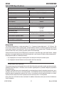
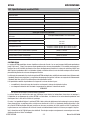
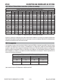
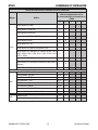
2.02 N7500 Specifications
Rated Output
Output Current
400-1600
Duty Cycle
MAX. 1600A/42V @ 100%
Open Circuit Voltage Minimum of 60VDC
Rated Input
Rated Input Voltage 110V - 220V
Rated Input Amperage
5A
Input Frequency 50/60 Hz
Control Box Controls
5A Circuit Breaker ON/OFF Switch w/reset ON/OFF Switch w/reset
110V/220V Control Box Power Input 3-Pin Socket
110V Auxiliary Outlet 4A, 110V
220V Auxiliary Outlet 4A, 220V
(2) 5A Circuit Breaker
1 off push-button circuit breaker for the 110V outlet
1 off push-button circuit breaker for the 220V outlet
Circuit Interface to Remote Pendant 7-Pin Socket
Circuit Interface to Torch Head 6-Pin Socket
Circuit Interface to Power Supply 6-Pin Socket
Signal Interface to Work Piece 1-Pin Socket
Table 2-1: N7500 Specifications
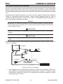
N7500 SYSTEM
The N7500 System produces in a single pass uniform “U” or “J” grooves of various depths up to 1-1/8” (28.6 mm). Two
or more passes produce grooves of greater depth. Through continuous control of arc voltage or amperage and a constant
travel speed, the groove is held within 0.025” (0.635 mm) target depth. Arcair Jointed Jetrods
®
Electrodes, with tapered
male and female ends, make it possible to produce grooves of unlimited length.
Control elements and circuitry for the N7500 System are housed in a Control Box and a splash-proof Pendant. Gouging
operations are managed remotely using the Remote Pendant with a multi-function LCD display and touch pad controls.
Groove depth and width are controlled in two ways:
• By changing the travel carriage’s forward speed or by changing the work piece rotational speed.
• By changing the electrode’s diameter and increasing or decreasing amperage.
NOTE
Remote Pendant is NOT submersible.
This manual has been structured to provide the user with all the information required for assembly, operation and trouble-
shooting of the N7500 System. Illustrations, charts and other supporting data are provided to bridge the gap between
theory and practice.
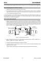
In addition, the N7500 System can be integrated with any mechanized travel system that provides forward travel over a
steel plate while in the flat, vertical, or over-head positions. The N7500 Torch Head can also be mounted in a stationary
position for work on rotating shafts, round steel, or a vessel. In a stationary set up the work-piece rotates in a
counter-
clockwise direction
and the Torch Head is generally located at the work-piece’s 4 o’clock position.
Refer to Form No. 89-250-894 for further clarification. For additional information, contact your local Arcair Distributor or
Victor Technologies.

Manual 89250890 3-1 SYSTEM COMPONENT DESCRIPTION
SYSTEM COMPONENT DESCRIPTION N7500
SECTION 3:
SYSTEM COMPONENT DESCRIPTION
There are three (3) main components making up the Arcair-Matic N7500 Gouging System; Torch Head, Control Box, and
Remote Pendant.
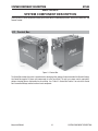
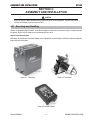
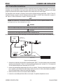
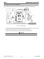
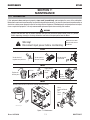
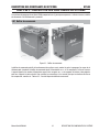
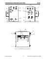
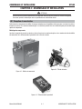
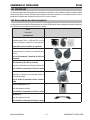
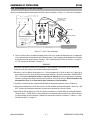
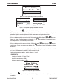
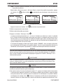
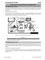
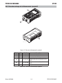
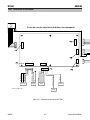
3.01 Control Box
ART# A-10928_AC
ART# A-10855_AC
Figure 3-1: Control Box
The Control Box controls the system’s operation before, during and after gouging. Under command of the Remote Pendant,
the Control Box supplies DC power and compressed air to the Torch Head. The unit has a power cord for required AC
voltage, clamping fixtures, and handles for secure lifting. See “Table 3-2: Control Box Features” for each of the Control
Box’s connectors/fittings and the function of each component.

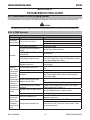
SYSTEM COMPONENT DESCRIPTION 3-2 Manual 89250890
N7500 SYSTEM COMPONENT DESCRIPTION
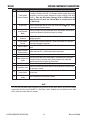
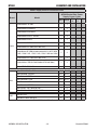
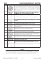
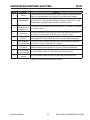
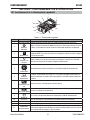
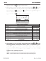
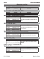
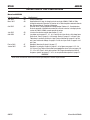
Item Fitting Function
1
Travel System
Power Connector
Two (2) 4 amp AC power receptacles provide AC power for a travel system
if needed, 110 VAC or 220 VAC. The Remote Pendant controls when these
receptacles receive AC power through the Remote Pendant travel delay
circuitry. Only the AC power voltage (110V or 220V from the
Input Power AC) that the Control Box is connected to will
be delivered.
2 Air Out Conn.
Delivers compressed shop air to the Torch Head when the
START
“Start” button
is pressed on the Remote Pendant.
3
Connector to Torch
Head Electrode
Motor
Delivers the signal from the Control Box to the Torch Head to either feed or
retract the electrode to maintain the preset arc voltage.
4
Remote Pendant
Connector
Links the Remote Pendant to the Control Box to initiate start/stop of the
gouging operation.
5
Circuit Breaker
w/reset
Circuit breaker reset push button for 110 VAC and 220 VAC AC Travel Sys-
tem Power Connector receptacles.
6 ON/OFF switch
Control Box ON/OFF control switch with built in 5 amp circuit breaker and
reset.
7
Input and Output
DC Power Conn.
Output and Input DC (+) positive power buss connections.
8 Air In Conn. This port accepts compressed shop air to the Control Box.
9
Power Supply Con-
nector
Links the Control Box to the Power Supply. On demand from the Remote
Pendant the internal contactor of the Power Supply can be closed and
opened to deliver the current to the Torch Head.
10 Input Power (AC) Delivers AC voltage to the Control Box from a standard wall receptacle.
11 Signal Wire Conn.
Allows the Control Box to detect open circuit voltage when the Power Sup-
ply contactor is closed.
12
Control Box Hold
Down Fixture
Hold down fixtures located on both sides of the Control Box to allow fasten-
ing to a base.
13
Remote Pendant
Cradle
Secure holding fixture for Remote Pendant.
Table 3-2: Control Box Features
NOTE
The 110V and 220V power supply receptacles may be used to run any device that has the same line-voltage
requirements and that require “ON-OFF” or “Start-Stop” control. However, any such device must be rated
with a maximum current draw of 4 amperes.

Manual 89250890 3-3 SYSTEM COMPONENT DESCRIPTION
SYSTEM COMPONENT DESCRIPTION N7500
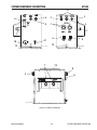
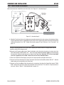
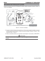
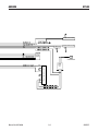
MAX 100 psi
7
10
6
8
9
11
12
ART# A-10851_AC
(Rear panel assembly
not shown for clarity)
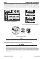
Figure 3-3: LEFT Side of Control Box
7
ART# A-10844_AB
5
5
12
(Rear panel assembly
not shown for clarity)
5 AMP
5 AMP
1
2
3
4
13
Figure 3-4: RIGHT Side of Control Box
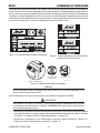
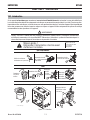
WARNING! AVERTISSEMENT!
Insure good ground from power supply to workpiece. Poor ground may cause
damage to any or all components. Use only with compressed air. See manual.
Smoke, fumes, and gases can be dangerous to your health. Use adequate
ventilation. Keep your head out of the smoke.
Protect yourself and others. Wear ear, eye, and body protection.
Noise can damage hearing.
Electric shock can cause injury or death. Disconnect power before servicing.
Arc rays, hot slag, and sparks can injure eyes and burn skin.
Welding sparks can cause res and explosions.
Assurez la bonne terre de l'alimentation d'énergie à l'objet. La terre pauvre peut endommager
quelques des ou tous composants. Employez seulement avec l'air comprimé. Voir le manuel.
La fumée, les émanations et les gaz peuvent être dangereux pour votre santé.
Employez à ventilation proportionnée. Gardez votre tête hors de la fumée.
Protégez-vous et d'autres. Portez l'oreille, l'oeil, et la protection de corps.
Le bruit peut endommager l’ouïe.
Un choc électrique peut causer des blessures ou la mort. Déconnectez la puissance
avant l'entretien.
L les rayons de l’arc,
es scories et les étincelles chauds peuvent blesser les yeux et brûler la peau.
Les étincelles de soudage peuvent causer des incendies et des explosions.
POWER
SUPPLY IN
POWER
SUPPLY OUT
7
6
8
2
ART# A-10853_AB
(rear cover plate not shown for clarity)
13
Figure 3-5: BACK of Control Box

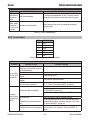
SYSTEM COMPONENT DESCRIPTION 3-4 Manual 89250890
N7500 SYSTEM COMPONENT DESCRIPTION
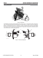
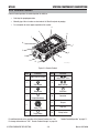
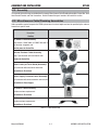
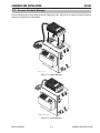
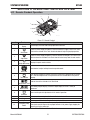
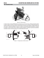
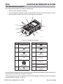
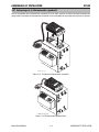
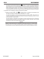
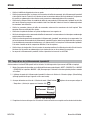
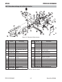
3.02 Torch Head
ART# A-10838_AB
Figure 3-6: Torch Head
The N7500 Torch Head feeds the jointed electrodes down to the work surface. The Control Box controls and signals the
motor on the Torch Head to feed or retract the electrode. This action maintains arc voltage or current, set on the Remote
Pendant. The Control Box (See “Figure 3-1: Control Box” on page 3-1) channels the DC current from the DC Welding
Power Supply to the Torch Head using standard welding cables. Compressed air coming from the Control Box connects
at the Torch Head with a 3/8” NPT female pipe elbow.
- 5/16 3/8
- 1/2
- 5/8
- 3/4
N7500
4
5
7
1
6
2
3
ART# A-10833_AC
8
9
Figure 3-7: Torch Head Components
La page est en cours de chargement...
La page est en cours de chargement...
La page est en cours de chargement...
La page est en cours de chargement...
La page est en cours de chargement...
La page est en cours de chargement...
La page est en cours de chargement...
La page est en cours de chargement...
La page est en cours de chargement...
La page est en cours de chargement...
La page est en cours de chargement...
La page est en cours de chargement...
La page est en cours de chargement...
La page est en cours de chargement...
La page est en cours de chargement...
La page est en cours de chargement...
La page est en cours de chargement...
La page est en cours de chargement...
La page est en cours de chargement...
La page est en cours de chargement...
La page est en cours de chargement...
La page est en cours de chargement...
La page est en cours de chargement...
La page est en cours de chargement...
La page est en cours de chargement...
La page est en cours de chargement...
La page est en cours de chargement...
La page est en cours de chargement...
La page est en cours de chargement...
La page est en cours de chargement...
La page est en cours de chargement...
La page est en cours de chargement...
La page est en cours de chargement...
La page est en cours de chargement...
La page est en cours de chargement...
La page est en cours de chargement...
La page est en cours de chargement...
La page est en cours de chargement...
La page est en cours de chargement...
La page est en cours de chargement...
La page est en cours de chargement...
La page est en cours de chargement...
La page est en cours de chargement...
La page est en cours de chargement...
La page est en cours de chargement...
La page est en cours de chargement...
La page est en cours de chargement...
La page est en cours de chargement...
La page est en cours de chargement...
La page est en cours de chargement...
La page est en cours de chargement...
La page est en cours de chargement...
La page est en cours de chargement...
La page est en cours de chargement...
La page est en cours de chargement...
La page est en cours de chargement...
La page est en cours de chargement...
La page est en cours de chargement...
La page est en cours de chargement...
La page est en cours de chargement...
La page est en cours de chargement...
La page est en cours de chargement...
La page est en cours de chargement...
La page est en cours de chargement...
La page est en cours de chargement...
La page est en cours de chargement...
La page est en cours de chargement...
La page est en cours de chargement...
La page est en cours de chargement...
La page est en cours de chargement...
La page est en cours de chargement...
La page est en cours de chargement...
La page est en cours de chargement...
La page est en cours de chargement...
La page est en cours de chargement...
La page est en cours de chargement...
La page est en cours de chargement...
La page est en cours de chargement...
La page est en cours de chargement...
La page est en cours de chargement...
La page est en cours de chargement...
La page est en cours de chargement...
La page est en cours de chargement...
La page est en cours de chargement...
La page est en cours de chargement...
La page est en cours de chargement...
La page est en cours de chargement...
La page est en cours de chargement...
La page est en cours de chargement...
La page est en cours de chargement...
La page est en cours de chargement...
La page est en cours de chargement...
La page est en cours de chargement...
La page est en cours de chargement...
La page est en cours de chargement...
La page est en cours de chargement...
La page est en cours de chargement...
La page est en cours de chargement...
La page est en cours de chargement...
La page est en cours de chargement...
La page est en cours de chargement...
La page est en cours de chargement...
La page est en cours de chargement...
La page est en cours de chargement...
La page est en cours de chargement...
La page est en cours de chargement...
La page est en cours de chargement...
La page est en cours de chargement...
La page est en cours de chargement...
La page est en cours de chargement...
La page est en cours de chargement...
La page est en cours de chargement...
-
 1
1
-
 2
2
-
 3
3
-
 4
4
-
 5
5
-
 6
6
-
 7
7
-
 8
8
-
 9
9
-
 10
10
-
 11
11
-
 12
12
-
 13
13
-
 14
14
-
 15
15
-
 16
16
-
 17
17
-
 18
18
-
 19
19
-
 20
20
-
 21
21
-
 22
22
-
 23
23
-
 24
24
-
 25
25
-
 26
26
-
 27
27
-
 28
28
-
 29
29
-
 30
30
-
 31
31
-
 32
32
-
 33
33
-
 34
34
-
 35
35
-
 36
36
-
 37
37
-
 38
38
-
 39
39
-
 40
40
-
 41
41
-
 42
42
-
 43
43
-
 44
44
-
 45
45
-
 46
46
-
 47
47
-
 48
48
-
 49
49
-
 50
50
-
 51
51
-
 52
52
-
 53
53
-
 54
54
-
 55
55
-
 56
56
-
 57
57
-
 58
58
-
 59
59
-
 60
60
-
 61
61
-
 62
62
-
 63
63
-
 64
64
-
 65
65
-
 66
66
-
 67
67
-
 68
68
-
 69
69
-
 70
70
-
 71
71
-
 72
72
-
 73
73
-
 74
74
-
 75
75
-
 76
76
-
 77
77
-
 78
78
-
 79
79
-
 80
80
-
 81
81
-
 82
82
-
 83
83
-
 84
84
-
 85
85
-
 86
86
-
 87
87
-
 88
88
-
 89
89
-
 90
90
-
 91
91
-
 92
92
-
 93
93
-
 94
94
-
 95
95
-
 96
96
-
 97
97
-
 98
98
-
 99
99
-
 100
100
-
 101
101
-
 102
102
-
 103
103
-
 104
104
-
 105
105
-
 106
106
-
 107
107
-
 108
108
-
 109
109
-
 110
110
-
 111
111
-
 112
112
-
 113
113
-
 114
114
-
 115
115
-
 116
116
-
 117
117
-
 118
118
-
 119
119
-
 120
120
-
 121
121
-
 122
122
-
 123
123
-
 124
124
-
 125
125
-
 126
126
-
 127
127
-
 128
128
-
 129
129
-
 130
130
-
 131
131
-
 132
132


Arcair N7500 Gouging System Manuel utilisateur
- Catégorie
- Système de soudage
- Taper
- Manuel utilisateur
- Ce manuel convient également à
dans d''autres langues
Documents connexes
-
Arcair CSK4000 Air Carbon-Arc Manual Gouging Torch Manuel utilisateur
-
Arcair Air Carbon-Arc Manuel utilisateur
-
-
-
 Arcair SLICE® NEW Exothermic Cutting Equipment Manuel utilisateur
-
 Arcair SLICE® NEW Exothermic Cutting Equipment Manuel utilisateur


Autres documents
-
Miller KG191348 Le manuel du propriétaire
-
Miller KK057228 Le manuel du propriétaire
-
-
-
-
-
 Tweco Air-Cooled 350 AMP 450 AMP Water-Cooled 400 AMP 500 AMP PulseMaster™ Mig Gun Manuel utilisateur
