
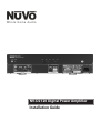
NV-D2120 Digital Power Amplifier
Installation Guide


ENGLISH

FRENCH
DURE EN HEURES PAR JOUR 8 6 4 3 2 1
INIVEAU SONORE CONTINU EN dB 90 93 95 97 100 103
Danger
L‘exposition a des niveaux eleves de bruit peut provoquer une perte
permanente de l’audition, Chaque organisme humain reagit
differemment quant a la perte de l’audition, mais quasiment tout le
monde subit une diminution de I’acuite auditive lors d’une exposition
suffisamment longue au bruit intense. Les autorites competentes en
reglementation de bruit ont defini les expositions tolerees aux niveaux
de bruits:
Selon les autorites, toute exposition dans les limites citees ci-dessus,
peuvent provoquer certaines pertes d’audition. Des bouchons ou
protections dans l’appareil auditif ou sur l’oreille doivent etre portes lors
de l’utilisation de ce systeme d’amplification afin de prevenir le risque
de perte permanente de l’audition, Dans le cas d’expositions
superieures aux limites precitees il est recommande, afin de se
premunir contre les expositions aux pressions acoustiquese I evees
potentielIement dangeure u ses, aux personnes exposees aux
equipements capables de delivrer de telles puissances, tels ce
systeme d’amplification en fonctionnement, de proteger l’appareil
auditif.
ATTENTION: AFIN DE LlMlTER LE RISQUE DE CHO ELECTR/QUE, NE
PAS ENLEVER LE CHASSIS. NE CONTIENT PAS DE
PIECES POUVANT ETRE REPAREE PAR L’UTILISATEUR.
CONFER LE SERVICE APRES-VENTE AUX
REPARATEURS
ATTENTION
RISQUE DE CHOC ELECTRIQUE
NE PAS OUVRIR.
CE SYMBOLE A POUR BUT D'AVERTIR L'UTILISATEUR DE LA PRESENCE
DE VOLTAGE DANGEREUX NON-ISOLE A L'INTERIEUR DE CE PRODUIT
QUI PEUT ETRE DE PUISSANCE SUFFISAMMENT IMPORTANTE POUR
PROVOQUER UN CHOC ELECTRIQUE AUX PERSONNES.
CE SYMBOLE A POUR BUT D'AVERTIR L'UTILISATEUR DE LA PRESENCE
D'INSTRUCTIONS D'UTILISATION ET DE MAINTENANCE DANS LES
DOCUMENTS FOURNIS AVEC CE PRODUIT.
IMPORTANTES INSTRUCTIONS DE SECURITE
1. Lire avec attention toutes les recommandations et précautions d'emploi avant
d'utiliser ce produit.
2. Toutes les recommandations et précautions d'emploi doivent être conservées
afin de pouvoir s'y reporter si nécessaire.
3. Lire et comprendre tous les avertissements énumérés dans les précautions
d'emploi.
4. Suivre toutes les précautions d'emploi pour utiliser ce produit.
5. Ce produit ne doit pas être utilisé près d'eau, comme par exemple baignoires,
éviers, piscine, sous-sol humides ... Etc.
6. Utiliser exclusivement un chiffon sec pour nettoyer ce produit.
7. Ne bloquér aucune ouverture de ventilation. Ne pas placer le produit tout
contre un mur ou dans une enceinte fernée, cela gênerait le flux d'air
nécessaire au refroidissement.
8. Ne pas placer le produit près de toute source de chaeur telle que radiateurs,
arrivées d'air chaud, fourneaux ou autres appareils générant de la chaleur
(incluant les amplificateurs producteurs de chaleur) .
9. Ne pas négliger la sécurité que procure un branchement polarisé ou avec
raccordement à la terre, Un branchement polarisé comprend deux fiches dont
l'une est plus large que l'autre. Un branchement à la terre comprend deux
fiches plus une troisième reliée à la terre. Si la fiche secteur fournie ne s'insert
pas dans votre prise de courant. consulter un 'électricien afin de remplacer
votre prise obsolète.
10. Protéger le cordon d'alimentation de tout écrasement ou pincement,
particulièrement au niveau des fiches, des réceptacles utilisés et à l'endroit de
sortie de l'appareil. Ne pas casser la fiche de terre du cordon d'alimentation.
11. Utiliser uniquement les accessoires spécifiés par le constructeur.
12. Utiliser uniquement avec le chariot de transport, le support, le trépied, la
console ou la table spécifiés par le constructeur ou vendus avec l'appareil. Lors
de l'utilisation d'un chariot, bouger avec précaution l'ensemble
chariotlappareil afin d'éviter les dommages d'un renversement.
13 Débrancher cet appareil lors d'orages ou s'il n'est pas utilisé pendant une
longue période.
14. Des précautions doivent être prises afin qu'aucun objet ne tombe et qu'aucun
liquide ne se répande à l'intérieur de l'appareil par les orifics de ventilation ou
n'importe quelle autre ouverture.
15. Pour toutes interventions techniques s'adresser à un technicien
qualifié.L'intervention technique est nécessaire lorsque l'appareil a été
endommagé de n'importe quelle façon, comme par exemple si le cordon
secteur ou sa fiche sont détériorés,si du liquide a coulé ou si des objets sont
tombés à l'intérieur de l'apparei1,si l'appareil a été exposé à la pluie ou à
l'humidité, s'il ne fonctionne pas normalement ou s'il est tombé.
16. ATTENTI0N:Pour réduire le risque d'incendie ou de choc electrique ne pas
exposer l'appareil à la pluie ou à l'humidité.
AFIN DE REDUIRE LES RISQUÉ D'INCENDIE ET DE DECHARGE
ELECTRIQUE, NE PAS EXPOSER CET APPAREIL A LA PLUIE OU A
L'HUMIDITE.

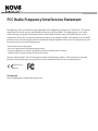
FCC Radio Frequency Interference Statement
This equipment has been tested and found to comply with the limits for Class B digital device, pursuant to Part 15 of the FCC rules. These limits are
designed to provide reasonable protection against harmful interference in a residential installation. This equipment generates, uses, and can
radiate radio frequency energy and, if not installed and used in accordance with the instructions, it may cause harmful interference to radio
communications. However, there is no guarantee that interference will not occur in a particular installation. If this equipment does cause harmful
interference to radio or television reception, which can be determined by turning the equipment off and on, the user is encouraged to try to correct
the interference by one or more of the following measures:
- Reorient or relocate the receiving antenna.
- Increase the separation between the equipment and the receiver.
- Connect the equipment into an outlet on a circuit different from that to which the receiver is connected.
- Consult the dealer or an experienced radio/TV technician for assistance.
This device complies with Part 15 of the FCC rules. Operation is subject to the following two conditions: (1) This device may not cause harmful
interference, and (2) this device must accept any interference received, including interference that may cause undesired operation.
IC Statement
This class B digital apparatus complies with Canadian ICES-003.
EN55022 Class-B
EN55024

Introduction
Congratulations on your purchase of the NuVo NV-D2120 Digital Power Amplifier. This robust amplifier will provide 120 watts to each of its two
speaker outputs, allowing for versatile uses powering any indoor or outdoor audio zone in multiple speaker configurations. The digital power supply
and digital class D amplification allows this single rack space mountable unit will provide quality audio to your speakers while consuming less
power than other standalone amplifiers.
Stable at four or eight ohms, and with multiple trigger options, the NV-D2120 offers the ultimate flexibility with the quality of construction you
have come to expect from NuVo Technologies.
6
Table of Contents:
Introduction........................................................................................................................................................................................
Front Panel..........................................................................................................................................................................................
Back Panel...........................................................................................................................................................................................
Wiring Diagram..................................................................................................................................................................................
I. Audio Inputs.....................................................................................................................................................................................
II Sensitivity Control...........................................................................................................................................................................
III. Power Mode...................................................................................................................................................................................
IV. Trigger In.........................................................................................................................................................................................
V. Unit On.............................................................................................................................................................................................
VI. Speaker Impedance......................................................................................................................................................................
VII. Speaker Outputs..........................................................................................................................................................................
Specifications.....................................................................................................................................................................................
NV-D2120 Package Contents
SKU Description Quantity
NV-D2120 Digital Power Amplifier 2 x 120 1
NV-CMRS3B-A Mini to RCA Stereo Audio Cable 1
NV-REM1U-C Single Space Rack Ear Mount (pair) 1
NV-PC2-NA-A North American 2-wire Power Cable 1
NV-CMM3B 3.5MM Mini Mono Cable 1
Page 6
Page 7
Page 8
Page 9
Page 10
Page 11
Page 11
Page 13
Page 13
Page 13
Page 14
Page 15

1
5
2
7
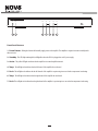
Front Panel Features
1. Power Button: Pushing this button will manually supply power to the amplifier. The amplifier is designed to remain in standby mode
when not in use.
2. Standby: This LED (light emitting diode) will light blue when the D2120 is plugged into an A/C power supply.
3. Active: This yellow LED lights to indicate that the amplifier is in normal amplification mode.
4. Temp: This will light red to indicate that the left channel of the amplifier has overheated.
5. Fault: This will light red to indicate that the left channel of the amplifier is experiencing issues not related to temperature/overheating.
6. Temp: This will light red to indicate that the right channel of the amplifier has overheated.
7. Fault: This will light red to indicate that the right channel of the amplifier is experiencing issues not related to temperature/overheating.
7
3 4
STAND BY
ACTI VE
TEMP
POWE R
MODEL NV-D2120
Digital Power Amplifier, 2x120W
FAULT TEMP FAULT
L R
6

1
6
7
8
2
3
4
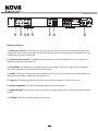
Back Panel Features
1. Audio Source Input: The D2120 will accept any line level stereo audio signal. This can be from the preamp lineout of a multi-source,
multi-zone whole house system such as the NuVo Essentia E6G and Grand Concerto systems, or the audio output of any non-amplified source, such
as an AM/FM tuner, CD player, or Satellite receiver.
2. Sensitivity Gain Control: Left and Right Channel Sensitivity trim pots allow the incoming signal to be increased or decreased to
maximize the potential output of the audio source.
3. Power Mode: This switch dictates how the amplifier responds to external triggers. The D2120 has 3 trigger methods: Incoming audio
signal, external voltage input, or the power button on the front of the amplifier.
4. Unit On: This provides a 12V trigger output when the amplifier is powered on. This can be used to turn on external audio equipment, daisy
chain multiple external amplifiers, or trigger a relay switching power strip.
5. Trigger In: This voltage trigger input allows the D2120 to power up whenever a voltage of 3-30 volts AC or DC is present.
6. Speaker Impedance: This switch sets the impedance stability at either four or eight ohms.
7. Speaker Output: The speaker output attaches to the amplifier via a modular plug and provides 120 Watts per channel output at either 4
or 8 ohms.
8. AC Power: The D2120 is designed to plug into any AC power source.
8
seri al n um ber
CONF ORMS T O UL
STD. 6006 5 CERTIF IED
TO CAN /CSA STD .
C22. 2 No.6 0065:0 6
N18 39
RoHS
This device complies with Part 15 of the FCC Rules.
Operation is subject to the following two conditions:
(1) This device may not cause harmful interference, and
(2) this device must accept any interference received,
including interference that may cause undesired operation.
303 3118
5

seri al n um ber
CONF ORMS TO UL
STD. 6006 5 CERTIF IED
TO CAN /CSA STD .
C22. 2 No.6 0065:0 6
N18 39
RoHS
This device complies with Part 15 of the FCC Rules.
Operation is subject to the following two conditions:
(1) This device may not cause harmful interference, and
(2) this device must accept any interference received,
including interference that may cause undesired operation.
303 3118
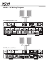
NV-D2120 Wiring Diagram
R
OUTPUT POWER
OUTPUT POWER
20W/6OHM X2
20W/6OHM X2
SYS ON
EXT. MUTE
L
R
L
R
L
R
VARI ABLE
OUTP UT
FIXE D
OUTP UT
SUM1
303 3118
C
US
CON FORMS T O
UL ST D. 650 0
CER TI FI ED TO
CAN /CSA STD .E600 65
NuVo Tec hnolo gies Ci ncinn ati Ohi o USA
FUS E:T5 A
120 V 60Hz 50 0W
MOD EL NV-I8D M
SIX S OURCE E IGHT ZON E
AUD IO DIST RIBUT ION SYST EM
www. nuvot echno logie s.com
OUTPUT POWER
OUTPUT POWER
OUTPUT POWER
20W/6OHM X2
20W/6OHM X2
20W/6OHM X2
TIP= L
RING =R
VARI ABLE
OUTP UT
FIXE D
OUTP UT
TIP= L
RING =R
VARI ABLE
OUTP UT
FIXE D
OUTP UT
TIP= L
RING =R
VARI ABLE
OUTP UT
FIXE D
OUTP UT
TIP= L
RING =R
VARI ABLE
OUTP UT
FIXE D
OUTP UT
TIP= L
RING =R
VARI ABLE
OUTP UT
VARI ABLE
OUTP UT
FIXE D
OUTP UT
FIXE D
OUTP UT
TIP= L
RING =R
TIP= L
RING =R
1 2 3 4 5
6
1 2 3 4 5
6
2 3
4
1 2 3
RS-2 32
CONN EC T TO
NV-I8 X
USE NV- SL C1
CABL E
CONN EC T TO
NV-I8 X
USE NV- SL C1
CABL E
CONN EC T TO
NV-I8 EZ P1
USE NV- NC 1
CABL E
USE CNLY WITH 250V FUSE
4
5
6
SUM2
5 6 7
8
OUTPUT POWER
20W/6OHM X2
ZONE 6ZONE 6
ZONE 7& 8
SYSTE M
ZONE TR IGGE R OUTP UTS
SOURCE LINK
SOURC E INPU TS
ZONE 1
NETWO RK
EMITT ER OUT PUTS DIGITAL LI NK
ZONE 3
ZONE 4
ZONE 5
ZONE 2
PROGR AM
6
4
5
3
1
2
SOURCE STATUS INPUT S
1
5 6
FIXED VAR
ZONE
1
TRIG
ZONE
2
STATUS
NuVoNet
RS232
1
SUM
ALLPORT CONNECTION
IR OUTPUTS
2 3 4 5 6
LINK
MUTE
180 7
N183 9
www. nuvo tec hnolo gies. com
MODEL NV-E 6G M
SIX S OURCE S IX ZONE
AUD IO DIST RIBUT ION SYS TEM
3033 118
NuVo Tec hnol ogi es LLC Heb ron, Ke ntuck y USA •
CONF ORMS TO UL
STD. 6006 5 CERTIF IED
TO CAN /CSA STD .
C22. 2 No.6 0065:0 3
RoHS
MADE IN CHINA
100 ~24 0V 50~60 Hz 130W
seri al n um ber
CONF ORMS TO UL
STD. 6006 5 CERTIF IED
TO CAN /CSA STD .
C22. 2 No.6 0065:0 6
N18 39
RoHS
This device complies with Part 15 of the FCC Rules.
Operation is subject to the following two conditions:
(1) This device may not cause harmful interference, and
(2) this device must accept any interference received,
including interference that may cause undesired operation.
303 3118
NV-D2120 with Grand Concerto System
NV-D2120 with Essentia E6G System
9

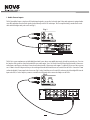
I. Audio Source Inputs
The D2120 amplifier features a single stereo RCA audio input designed to accept a line level audio signal. Most audio equipment is equipped with a
stereo RCA output that allows the audio signal to be taken directly to the D2120’s audio input. This is accomplished using a standard stereo audio
cable with left and right audio jacks on each end (Fig. 1).
Fig. 1
The D2120 is a great complement to any NuVo Multi Room Audio System, where extra amplification may be desired for a particular zone. Zone 4 on
the Simplese audio system has a fixed and variable RCA stereo audio output. Zones 1 & 2 on the Essentia E6G have fixed and variable 3.5mm stereo
audio outputs, and all zones on the Grand Concerto have fixed and variable 3.5mm stereo audio outputs. To add the D2120 to one of these systems,
use a 3.5mm to Stereo RCA adapter cable to pass the audio signal from the NuVo Grand Concerto or Essentia E6G to the D2120. Connect the 3.5mm
end into the Variable 3.5mm output for the chosen zone (Fig. 2) on the Grand Concerto or Essentia E6G, and connect the left and right RCA’s into the
Input on the D2120. For the Simplese system use a standard stereo RCA patch cable to connect the Simplese to the D2120.
Fig. 2
10
5 6
FIXED VAR
ZONE
1
ZONE
2
TUNER BANTENNA INPUT
IN
USE ONLY Nu Vo
NV-T2PAS
POWER ED ANTENNA SYST EM
L
AUDIO O UT
AUX IN
R
TRIGG ER
ON=+1 2V
AUD IO
OUTPU T

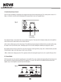
II. Audio Sensitivity Control
The D2120 allows the flexibility of controlling the left and right channel gains for the incoming audio signal. The sensitivity allows a control of -12
dB up to +6 dB, and is an excellent tool for maximizing the full output potential of your source equipment (Fig. 3).
Fig. 3
To best utilize this feature, set the volume for the source at its fullest output level. Then adjust the left and right sensitivity trims on the amplifier to
allow the fullest possible output from the speakers without distortion.
+6 or a counter-clockwise turn is used to reduce the gain. This would be the preferred setting for a distributed audio system with variable preamp
line outputs, such as any of the NuVo systems. Reducing the gain can also be useful for limiting the maximum power going to the speakers.
0 or straight vertically is the factory default. This is the preferred setting for an audio signal from a preamp, such as a distributed audio system with
a fixed preamp line output, or the audio output of a music server or CD player.
-12 or a clockwise turn is a high gain position. This is typically used when the incoming audio signal is weak, such as a portable CD player or iPod.
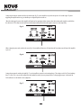
III. Power Mode
The D2120 provides three basic methods for supplying power to the amplifier. This can be accomplished by simply pushing the Power button on the
front of the unit, by sensing an incoming audio signal, or by supplying a 3-30 volt AC or DC current. The Power Mode switch on the back of the
amplifier (Fig. 4) sets the amplifier to respond to any of the three options.
Fig. 4
Left and Right
Sensitivity Trims
11

Setting the power mode switch to the left in the Audio mode (Fig. 5) sets the amplifier to respond to the presence of an audio signal. If you are
triggering the amplifier in this way, you should expect a slight delay before it turns on.
When the audio signal is removed the amplifier will remain on for approximately three minutes after the incoming audio signal has ended before
the unit turns off. This will prevent the unit from inadvertently turning off when the audio signal is very low or stops temporarily.
Fig. 5
When setting the power mode switch to the center (Fig. 6) the amplifier will turn on or off only when the Power button on the front of the amplifier
is pressed.
Fig. 6
Setting the power mode switch to the right (Fig. 7) sets the amplifier to respond to an incoming voltage. This voltage can be AC or DC and anything
from 3-30 volts. This is very useful in conjunction with a multiroom audio system or preamp that has a voltage trigger output. In this mode the
D2120 will turn on or off with the source equipment.
Fig. 7
12

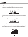
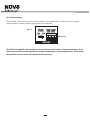
IV. Trigger In
This input (Fig. 8) is designed for a mono 1/8” plug to accept a trigger voltage coming in from an external source.
Any voltage ranging from 3 to 30 volts, AC or DC, will cause the amplifier to turn on when the Power switch is in the Trigger mode.
Fig. 8
V. Unit On
This output (Fig. 9) provides a constant 12 volts DC when the amplifier is powered on. This is useful for powering on external equipment with the
D2120.
Fig. 9
VI. Speaker Impedance
This switch (Fig. 10) allows for the adjusting of the impedance of the amplifier. By default the amplifier will be set at 8 ohms. This is fine is you are
powering a pair of 8 ohm speakers, or a single stereo speaker rated at 8 ohms. In installations where three or more 8 ohm speakers will be used, or
a pair of 4 ohm speakers are being utilized, the impedance of the amplifier should be set to 4 ohms. The power of the output will remain at 120
watts per channel.
Fig. 10
13

14
VII. Speaker Outputs
The D2120 provides 120 watts of power per channel at four or eight ohms. It uses a modular plug (Fig. 11) that will accept up to 14 gauge, 4
conductor speaker wire. Stranded 4 conductor 16 gauge speaker wire is recommended.
Fig. 11
The NV-D2120 amplifier is designed to run at a maximum load of 4 ohms. Prolonged operation at less
than 4 ohms could cause the amplifier to overheat and damage its internal components. Overheating
the amplifier due to an excessive load will void the warranty.

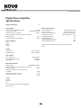
Digital Power Amplifier
Specifications
Number of Channels 2
Power Output
Continuous Average Output Power 2 x 120W
Two channels driven 20-20kHz @1% THD
Rated Distortion (1/2 power) 0.02%
Rated Impedance switch Selectable 4 or 8 Ohms
Damping Factor 50+
Frequency Response (20-20kHz) ±1 dB
Power-On Modes
Audio
Power
Trigger
System
Trigger Input 3-30 V AC or DC
Unit On Output +12VDC @100mA
Source Inputs
Input Impedance 22k ohm Input
Sensitivity for rated power .3-2V RMS
Input Overload 2.4V RMS
Power Requirements
Power Supply
Power Consumption both channels at maximum
available output
Power Consumption average operating
conditions
Power Consumption no signal
Standby Power Consumption
CE EMC
CE LVD
USA FCC
ETL
Canada Safety Listing (CAN/CSA E60065.00)
Australia C-Tick
Physical Specifications
Unit Size Millimeters
Unit Size Inches
Shipping Size Millimeters
Shipping Size Inches
Unit Weight Kilograms
Unit Weight Pounds
Shipping Weight Kilograms
Shipping Weight Pounds
NuVo reserves the right to change specifications without
notice.
15
100-240VAC 50/60Hz
340W
50W
12W
0.35W
44 H x 430 W x 250 D
1 3/4 H x 17 W x 9 7/8 D
205 H x 515 W x 343 D
8 H x 20 1/4 W x 13 1/2 D
3.0
6.6
4.8
10.5

NuVo Technologies Hebron, KY USA
www.nuvotechnologies.com
D2120 1033
-
 1
1
-
 2
2
-
 3
3
-
 4
4
-
 5
5
-
 6
6
-
 7
7
-
 8
8
-
 9
9
-
 10
10
-
 11
11
-
 12
12
-
 13
13
-
 14
14
-
 15
15
-
 16
16


dans d''autres langues
- English: Nuvo NV-D2120 Installation guide
Documents connexes
-
Nuvo Digital power Amplifier Guide d'installation
-
-
-
Nuvo Concerto NV-I8DMS Manuel utilisateur
-
-
-
-
-
-