Lincoln Electric IM823-A Manuel utilisateur
- Catégorie
- Système de soudage
- Taper
- Manuel utilisateur
Ce manuel convient également à

OPERATOR’S MANUAL
• Sales and Service through Subsidiaries and Distributors Worldwide •
Cleveland, Ohio 44117-1199 U.S.A. TEL: 216.481.8100 FAX: 216.486.1751 WEB SITE: www.lincolnelectric.com
• World's Leader in Welding and Cutting Products •
Copyright © Lincoln Global Inc.
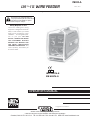
LN ™-15 WIRE FEEDER
IM823-A
March, 2010
For use with machines having Code Number : 11033, 11035, 11600
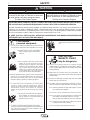
Safety Depends on You
Lincoln arc welding and cutting
equipment is designed and built with
safety in mind. However, your overall
safety can be increased by proper
installation ... and thoughtful opera-
tion on your part. DO NOT
INSTALL, OPERATE OR REPAIR
THIS EQUIPMENT WITHOUT
READING THIS MANUAL AND
THE SAFETY PRECAUTIONS
CONTAINED THROUGHOUT. And,
most importantly, think before you
act and be careful.
IEC 60974-5
N80
EN 60974-5
This manual covers equipment which is no
longer in production by The Lincoln Electric Co.
Specications and availability of optional
features may have changed.

FOR ENGINE
powered equipment.
1.a. Turn the engine off before troubleshooting and maintenance
work unless the maintenance work requires it to be running.
____________________________________________________
1.b. Operate engines in open, well-ventilated
areas or vent the engine exhaust fumes
outdoors.
____________________________________________________
1.c. Do not add the fuel near an open flame
welding arc or when the engine is running.
Stop the engine and allow it to cool before
refueling to prevent spilled fuel from vaporiz-
ing on contact with hot engine parts and
igniting. Do not spill fuel when filling tank. If
fuel is spilled, wipe it up and do not start
engine until fumes have been eliminated.
____________________________________________________
1.d. Keep all equipment safety guards, covers and devices in
position and in good repair.Keep hands, hair, clothing and
tools away from V-belts, gears, fans and all other moving
parts when starting, operating or repairing equipment.
____________________________________________________
1.e. In some cases it may be necessary to remove safety
guards to perform required maintenance. Remove
guards only when necessary and replace them when the
maintenance requiring their removal is complete.
Always use the greatest care when working near moving
parts.
___________________________________________________
1.f. Do not put your hands near the engine fan.
Do not attempt to override the governor or
idler by pushing on the throttle control rods
while the engine is running.
___________________________________________________
1.g. To prevent accidentally starting gasoline engines while
turning the engine or welding generator during maintenance
work, disconnect the spark plug wires, distributor cap or
magneto wire as appropriate.
i
SAFETY
i
ARC WELDING CAN BE HAZARDOUS. PROTECT YOURSELF AND OTHERS FROM POSSIBLE SERIOUS INJURY OR DEATH.
KEEP CHILDREN AWAY. PACEMAKER WEARERS SHOULD CONSULT WITH THEIR DOCTOR BEFORE OPERATING.
Read and understand the following safety highlights. For additional safety information, it is strongly recommended that you
purchase a copy of “Safety in Welding & Cutting - ANSI Standard Z49.1” from the American Welding Society, P.O. Box
351040, Miami, Florida 33135 or CSA Standard W117.2-1974. A Free copy of “Arc Welding Safety” booklet E205 is available
from the Lincoln Electric Company, 22801 St. Clair Avenue, Cleveland, Ohio 44117-1199.
BE SURE THAT ALL INSTALLATION, OPERATION, MAINTENANCE AND REPAIR PROCEDURES ARE
PERFORMED ONLY BY QUALIFIED INDIVIDUALS.
WARNING
Mar ‘95
ELECTRIC AND
MAGNETIC FIELDS
may be dangerous
2.a. Electric current flowing through any conductor causes
localized Electric and Magnetic Fields (EMF). Welding
current creates EMF fields around welding cables and
welding machines
2.b. EMF fields may interfere with some pacemakers, and
welders having a pacemaker should consult their physician
before welding.
2.c. Exposure to EMF fields in welding may have other health
effects which are now not known.
2.d. All welders should use the following procedures in order to
minimize exposure to EMF fields from the welding circuit:
2.d.1.
Route the electrode and work cables together - Secure
them with tape when possible.
2.d.2. Never coil the electrode lead around your body.
2.d.3. Do not place your body between the electrode and
work cables. If the electrode cable is on your right
side, the work cable should also be on your right side.
2.d.4. Connect the work cable to the workpiece as close as
possible to the area being welded.
2.d.5. Do not work next to welding power source.
1.h. To avoid scalding, do not remove the
radiator pressure cap when the engine is
hot.
CALIFORNIA PROPOSITION 65 WARNINGS
Diesel engine exhaust and some of its constituents
are known to the State of California to cause can-
cer, birth defects, and other reproductive harm.
The engine exhaust from this product contains
chemicals known to the State of California to cause
cancer, birth defects, or other reproductive harm.
The Above For Diesel Engines
The Above For Gasoline Engines

ii
SAFETY
ii
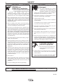
ARC RAYS can burn.
4.a. Use a shield with the proper filter and cover
plates to protect your eyes from sparks and
the rays of the arc when welding or observing
open arc welding. Headshield and filter lens
should conform to ANSI Z87. I standards.
4.b. Use suitable clothing made from durable flame-resistant
material to protect your skin and that of your helpers from
the arc rays.
4.c. Protect other nearby personnel with suitable, non-flammable
screening and/or warn them not to watch the arc nor expose
themselves to the arc rays or to hot spatter or metal.
ELECTRIC SHOCK can
kill.
3.a. The electrode and work (or ground) circuits
are electrically “hot” when the welder is on.
Do not touch these “hot” parts with your bare
skin or wet clothing. Wear dry, hole-free
gloves to insulate hands.
3.b. Insulate yourself from work and ground using dry insulation.
Make certain the insulation is large enough to cover your full
area of physical contact with work and ground.
In addition to the normal safety precautions, if welding
must be performed under electrically hazardous
conditions (in damp locations or while wearing wet
clothing; on metal structures such as floors, gratings or
scaffolds; when in cramped positions such as sitting,
kneeling or lying, if there is a high risk of unavoidable or
accidental contact with the workpiece or ground) use
the following equipment:
• Semiautomatic DC Constant Voltage (Wire) Welder.
• DC Manual (Stick) Welder.
• AC Welder with Reduced Voltage Control.
3.c. In semiautomatic or automatic wire welding, the electrode,
electrode reel, welding head, nozzle or semiautomatic
welding gun are also electrically “hot”.
3.d. Always be sure the work cable makes a good electrical
connection with the metal being welded. The connection
should be as close as possible to the area being welded.
3.e. Ground the work or metal to be welded to a good electrical
(earth) ground.
3.f.
Maintain the electrode holder, work clamp, welding cable and
welding machine in good, safe operating condition. Replace
damaged insulation.
3.g. Never dip the electrode in water for cooling.
3.h. Never simultaneously touch electrically “hot” parts of
electrode holders connected to two welders because voltage
between the two can be the total of the open circuit voltage
of both welders.
3.i. When working above floor level, use a safety belt to protect
yourself from a fall should you get a shock.
3.j. Also see Items 6.c. and 8.
FUMES AND GASES
can be dangerous.
5.a. Welding may produce fumes and gases
hazardous to health. Avoid breathing these
fumes and gases. When welding, keep
your head out of the fume. Use enough
ventilation and/or exhaust at the arc to keep
fumes and gases away from the breathing zone. When
welding with electrodes which require special
ventilation such as stainless or hard facing (see
instructions on container or MSDS) or on lead or
cadmium plated steel and other metals or coatings
which produce highly toxic fumes, keep exposure as
low as possible and within applicable OSHA PEL and
ACGIH TLV limits using local exhaust or mechanical
ventilation. In confined spaces or in some circum-
stances, outdoors, a respirator may be required.
Additional precautions are also required when welding
on galvanized steel.
5. b. The operation of welding fume control equipment is affected
by various factors including proper use and positioning of
the equipment, maintenance of the equipment and the spe-
cific welding procedure and application involved. Worker
exposure level should be checked upon installation and
periodically thereafter to be certain it is within applicable
OSHA PEL and ACGIH TLV limits.
5.c.
Do not weld in locations near chlorinated hydrocarbon
vapors
coming from degreasing, cleaning or spraying operations.
The heat and rays of the arc can react with solvent vapors
to
form phosgene, a highly toxic gas, and other irritating prod-
ucts.
5.d. Shielding gases used for arc welding can displace air and
cause injury or death. Always use enough ventilation,
especially in confined areas, to insure breathing air is safe.
5.e. Read and understand the manufacturer’s instructions for this
equipment and the consumables to be used, including the
material safety data sheet (MSDS) and follow your
employer’s safety practices. MSDS forms are available from
your welding distributor or from the manufacturer.
5.f. Also see item 1.b.
Jan ‘09

iii
SAFETY
iii
FOR ELECTRICALLY
powered equipment.
8.a. Turn off input power using the disconnect
switch at the fuse box before working on
the equipment.
8.b. Install equipment in accordance with the U.S. National
Electrical Code, all local codes and the manufacturer’s
recommendations.
8.c. Ground the equipment in accordance with the U.S. National
Electrical Code and the manufacturer’s recommendations.
CYLINDER may explode
if damaged.
7.a. Use only compressed gas cylinders
containing the correct shielding gas for the
process used and properly operating
regulators designed for the gas and
pressure used. All hoses, fittings, etc. should be suitable for
the application and maintained in good condition.
7.b. Always keep cylinders in an upright position securely
chained to an undercarriage or fixed support.
7.c. Cylinders should be located:
• Away from areas where they may be struck or subjected to
physical damage.
• A safe distance from arc welding or cutting operations and
any other source of heat, sparks, or flame.
7.d. Never allow the electrode, electrode holder or any other
electrically “hot” parts to touch a cylinder.
7.e. Keep your head and face away from the cylinder valve outlet
when opening the cylinder valve.
7.f. Valve protection caps should always be in place and hand
tight except when the cylinder is in use or connected for
use.
7.g. Read and follow the instructions on compressed gas
cylinders, associated equipment, and CGA publication P-l,
“Precautions for Safe Handling of Compressed Gases in
Cylinders,” available from the Compressed Gas Association
1235 Jefferson Davis Highway, Arlington, VA 22202.
WELDING and CUTTING
SPARKS can
cause fire or explosion.
6.a.
Remove fire hazards from the welding area.
If this is not possible, cover them to prevent
the welding sparks from starting a fire.
Remember that welding sparks and hot
materials from welding can easily go through small cracks
and openings to adjacent areas. Avoid welding near
hydraulic lines. Have a fire extinguisher readily available.
6.b. Where compressed gases are to be used at the job site,
special precautions should be used to prevent hazardous
situations. Refer to “Safety in Welding and Cutting” (ANSI
Standard Z49.1) and the operating information for the
equipment being used.
6.c. When not welding, make certain no part of the electrode
circuit is touching the work or ground. Accidental contact
can cause overheating and create a fire hazard.
6.d. Do not heat, cut or weld tanks, drums or containers until the
proper steps have been taken to insure that such procedures
will not cause flammable or toxic vapors from substances
inside. They can cause an explosion even
though
they have
been “cleaned”. For information, purchase “Recommended
Safe Practices for the
Preparation
for Welding and Cutting of
Containers and Piping That Have Held Hazardous
Substances”, AWS F4.1 from the American Welding Society
(see address above).
6.e. Vent hollow castings or containers before heating, cutting or
welding. They may explode.
6.f.
Sparks and spatter are thrown from the welding arc. Wear oil
free protective garments such as leather gloves, heavy shirt,
cuffless trousers, high shoes and a cap over your hair. Wear
ear plugs when welding out of position or in confined places.
Always wear safety glasses with side shields when in a
welding area.
6.g. Connect the work cable to the work as close to the welding
area as practical. Work cables connected to the building
framework or other locations away from the welding area
increase the possibility of the welding current passing
through lifting chains, crane cables or other alternate cir-
cuits. This can create fire hazards or overheat lifting chains
or cables until they fail.
6.h. Also see item 1.c.
6.I. Read and follow NFPA 51B “ Standard for Fire Prevention
During Welding, Cutting and Other Hot Work”, available
from NFPA, 1 Batterymarch Park, PO box 9101, Quincy, Ma
022690-9101.
6.j. Do not use a welding power source for pipe thawing.
Jan ‘09
Refer to http://www.lincolnelectric.com/safety for additional safety information.

iv
SAFETY
iv
Mar. ‘93
PRÉCAUTIONS DE SÛRETÉ
Pour votre propre protection lire et observer toutes les instructions
et les précautions de sûreté specifiques qui parraissent dans ce
manuel aussi bien que les précautions de sûreté générales suiv-
antes:
Sûreté Pour Soudage A L’Arc
1. Protegez-vous contre la secousse électrique:
a. Les circuits à l’électrode et à la piéce sont sous tension
quand la machine à souder est en marche. Eviter toujours
tout contact entre les parties sous tension et la peau nue
ou les vétements mouillés. Porter des gants secs et sans
trous pour isoler les mains.
b. Faire trés attention de bien s’isoler de la masse quand on
soude dans des endroits humides, ou sur un plancher
metallique ou des grilles metalliques, principalement dans
les positions assis ou couché pour lesquelles une grande
partie du corps peut être en contact avec la masse.
c. Maintenir le porte-électrode, la pince de masse, le câble
de soudage et la machine à souder en bon et sûr état
defonctionnement.
d.Ne jamais plonger le porte-électrode dans l’eau pour le
refroidir.
e. Ne jamais toucher simultanément les parties sous tension
des porte-électrodes connectés à deux machines à souder
parce que la tension entre les deux pinces peut être le
total de la tension à vide des deux machines.
f. Si on utilise la machine à souder comme une source de
courant pour soudage semi-automatique, ces precautions
pour le porte-électrode s’applicuent aussi au pistolet de
soudage.
2. Dans le cas de travail au dessus du niveau du sol, se protéger
contre les chutes dans le cas ou on recoit un choc. Ne jamais
enrouler le câble-électrode autour de n’importe quelle partie
du corps.
3. Un coup d’arc peut être plus sévère qu’un coup de soliel,
donc:
a. Utiliser un bon masque avec un verre filtrant approprié
ainsi qu’un verre blanc afin de se protéger les yeux du ray-
onnement de l’arc et des projections quand on soude ou
quand on regarde l’arc.
b. Porter des vêtements convenables afin de protéger la
peau de soudeur et des aides contre le rayonnement de
l‘arc.
c. Protéger l’autre personnel travaillant à proximité au
soudage à l’aide d’écrans appropriés et non-inflammables.
4. Des gouttes de laitier en fusion sont émises de l’arc de
soudage. Se protéger avec des vêtements de protection libres
de l’huile, tels que les gants en cuir, chemise épaisse, pan-
talons sans revers, et chaussures montantes.
5. Toujours porter des lunettes de sécurité dans la zone de
soudage. Utiliser des lunettes avec écrans lateraux dans les
zones où l’on pique le laitier.
6. Eloigner les matériaux inflammables ou les recouvrir afin de
prévenir tout risque d’incendie dû aux étincelles.
7. Quand on ne soude pas, poser la pince à une endroit isolé de
la masse. Un court-circuit accidental peut provoquer un
échauffement et un risque d’incendie.
8. S’assurer que la masse est connectée le plus prés possible
de la zone de travail qu’il est pratique de le faire. Si on place
la masse sur la charpente de la construction ou d’autres
endroits éloignés de la zone de travail, on augmente le risque
de voir passer le courant de soudage par les chaines de lev-
age, câbles de grue, ou autres circuits. Cela peut provoquer
des risques d’incendie ou d’echauffement des chaines et des
câbles jusqu’à ce qu’ils se rompent.
9. Assurer une ventilation suffisante dans la zone de soudage.
Ceci est particuliérement important pour le soudage de tôles
galvanisées plombées, ou cadmiées ou tout autre métal qui
produit des fumeés toxiques.
10. Ne pas souder en présence de vapeurs de chlore provenant
d’opérations de dégraissage, nettoyage ou pistolage. La
chaleur ou les rayons de l’arc peuvent réagir avec les vapeurs
du solvant pour produire du phosgéne (gas fortement toxique)
ou autres produits irritants.
11. Pour obtenir de plus amples renseignements sur la sûreté,
voir le code “Code for safety in welding and cutting” CSA
Standard W 117.2-1974.
PRÉCAUTIONS DE SÛRETÉ POUR
LES MACHINES À SOUDER À
TRANSFORMATEUR ET À
REDRESSEUR
1. Relier à la terre le chassis du poste conformement au code de
l’électricité et aux recommendations du fabricant. Le dispositif
de montage ou la piece à souder doit être branché à une
bonne mise à la terre.
2. Autant que possible, I’installation et l’entretien du poste seront
effectués par un électricien qualifié.
3. Avant de faires des travaux à l’interieur de poste, la debranch-
er à l’interrupteur à la boite de fusibles.
4. Garder tous les couvercles et dispositifs de sûreté à leur
place.

v
SAFETY
v

vi
SAFETY
vi

vii
vii
Thank You
for selecting a QUALITY product by Lincoln Electric. We want you
to take pride in operating this Lincoln Electric Company product
••• as much pride as we have in bringing this product to you!
Read this Operators Manual completely before attempting to use this equipment. Save this manual and keep it
handy for quick reference. Pay particular attention to the safety instructions we have provided for your protection.
The level of seriousness to be applied to each is explained below:
WARNING
This statement appears where the information must be followed exactly to avoid serious personal injury or loss of life.
This statement appears where the information must be followed to avoid minor personal injury or damage to this equipment.
CAUTION
Please Examine Carton and Equipment For Damage Immediately
When this equipment is shipped, title passes to the purchaser upon receipt by the carrier. Consequently, Claims
for material damaged in shipment must be made by the purchaser against the transportation company at the
time the shipment is received.
Please record your equipment identification information below for future reference. This information can be
found on your machine nameplate.
Product _________________________________________________________________________________
Model Number ___________________________________________________________________________
Code Number or Date Code_________________________________________________________________
Serial Number____________________________________________________________________________
Date Purchased___________________________________________________________________________
Where Purchased_________________________________________________________________________
Whenever you request replacement parts or information on this equipment, always supply the information you
On-Line Product Registration
- Register your machine with Lincoln Electric either via fax or over the Internet.
• For faxing: Complete the form on the back of the warranty statement included in the literature packet
accompanying this machine and fax the form per the instructions printed on it.
• For On-Line Registration: Go to our
WEB SITE at www.lincolnelectric.com. Choose “Quick Links” and then
“Product Registration”. Please complete the form and submit your registration.
CUSTOMER ASSISTANCE POLICY
The business of The Lincoln Electric Company is manufacturing and selling high quality welding equipment, consumables, and cutting equip-
ment. Our challenge is to meet the needs of our customers and to exceed their expectations. On occasion, purchasers may ask Lincoln
Electric for advice or information about their use of our products. We respond to our customers based on the best information in our posses-
sion at that time. Lincoln Electric is not in a position to warrant or guarantee such advice, and assumes no liability, with respect to such infor-
mation or advice. We expressly disclaim any warranty of any kind, including any warranty of fitness for any customer’s particular purpose,
with respect to such information or advice. As a matter of practical consideration, we also cannot assume any responsibility for updating or
correcting any such information or advice once it has been given, nor does the provision of information or advice create, expand or alter any
warranty with respect to the sale of our products.
Lincoln Electric is a responsive manufacturer, but the selection and use of specific products sold by Lincoln Electric is solely within the control
of, and remains the sole responsibility of the customer. Many variables beyond the control of Lincoln Electric affect the results obtained in
applying these types of fabrication methods and service requirements.
Subject to Change – This information is accurate to the best of our knowledge at the time of printing. Please refer to www.lincolnelectric.com
for any updated information.

viii
viii
TABLE OF CONTENTS
Page
Installation.......................................................................................................................Section A
Technical Specifications.......................................................................................................A-1
Safety Precautions ...............................................................................................................A-2
Location................................................................................................................................A-2
Work Clip Lead.....................................................................................................................A-2
High Frequency Protection...................................................................................................A-2
Weld Cable Connections......................................................................................................A-3
Electrode Connection ...........................................................................................................A-3
Work Connection..................................................................................................................A-3
Power Source Connection....................................................................................................A-3
Engine Drive Power Source Connection ..............................................................................A-3
Connection Diagrams...........................................................................................................A-4
Gun and Cable Assemblies..................................................................................................A-5
Electrode Polarity .................................................................................................................A-5
Connections .........................................................................................................................A-5
Procedure to Install Drive Rolls and Wire Guides ................................................................A-5
Feed Wire Electrode.............................................................................................................A-6
________________________________________________________________________________
Operation.........................................................................................................................Section B
Safety Precautions ...............................................................................................................B-1
Graphic Symbols that appear on this Machine or in this Manual .........................................B-1
General Description..............................................................................................................B-2
Duty Cycle ............................................................................................................................B-2
Recommended Processes ...................................................................................................B-2
Process Limitations ..............................................................................................................B-2
Equipment Limitations ..........................................................................................................B-2
Operational Features and Controls .....................................................................................B-2
Case Front Controls .............................................................................................................B-3
83% Procedure.....................................................................................................................B-3
LN™-15 Power-Up Sequence ......................................................................................B-4, B-5
Internal Controls ...................................................................................................................B-5
Spring Tension Arm..............................................................................................................B-5
Wire Drive Configuration ......................................................................................................B-6
Cold Feed/Gas Purge Switch ...............................................................................................B-6
2 Step-Trigger Interlock Switch ............................................................................................B-7
Flow Meter............................................................................................................................B-7
Spindle Brake .......................................................................................................................B-7
Shielding Gas Connection....................................................................................................B-7
Constant Current Operation .................................................................................................B-8
Setting Arc Sensing wire Feed Speed For Constant Current Operation ..............................B-9
Making a Weld....................................................................................................................B-10
________________________________________________________________________________
Accessories ....................................................................................................................Section C
Factory Installed Equipment.................................................................................................C-1
Electrode, K-Kit used ...........................................................................................................C-1
________________________________________________________________________________
Maintenance....................................................................................................................Section D
Safety Precautions ...............................................................................................................D-1
Routine Maintenance ...........................................................................................................D-1
Periodic Maintenance...........................................................................................................D-1
Calibration Specification.......................................................................................................D-1
________________________________________________________________________________
Troubleshooting .................................................................................................................Section E
Safety Precautions ...............................................................................................................E-1
How to Use Troubleshooting Guide .....................................................................................E-1
Troubleshooting Guide ...........................................................................................E-2 thru E-4
________________________________________________________________________________
Wiring Diagram & Dimension Prints .............................................................................Section F
________________________________________________________________________________
Parts Pages ............................................................................................................................P-482
_______________________________________________________________________
________

15-110 VDC (5 Amps Maximum)
Across the Arc Model
300 Amps 60% Duty Cycle
250 Amps 100% Duty Cycle
A-1
INSTALLATION
LN™-15 ACROSS THE ARC MODEL & (CE)
A-1
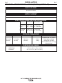
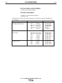
TEMPERATURE RANGE
OPERATION: - 20
o
C to +50
o
C (- 4
o
F to +122
o
F)
STORAGE: - 40
o
C to +70
o
C (- 40
o
F to +185
o
F)
RATED CURRENT
INPUT VOLTAGE
TECHNICAL SPECIFICATIONS – LN™-15 (K1870-1), (K1870-2 CE)
HEIGHT WIDTH DEPTH WEIGHT
12.7 Inches 8.7 Inches 23 Inches 30lbs
(323 mm) (221mm) (584 mm) (14kg)
SPOOL SIZE CAPABILITY
8 (200mm) Dia. x 4 (100mm)
Wide Spools including
AWS 8 DIA. (10-15lbs)
JIS S-3 200mm max. (5 - 7 kg)
DIN 200 (5 kg)
ELECTRODE DIAMETERS and SPEED RANGE
PHYSICAL DIMENSIONS
Electrode Size Speed Range
0.023 - 0.052" 50 - 700 in/min
(0.6 - 1.3 mm) (1.3 - 17.8 m/min)
0.0345 - 5/64" 50 - 400 in/min
(0.9 - 2.3 mm) (1.3 - 10.1 m/min)
Solid Electrode
Steel
Flux Cored
Electrode

A-2
INSTALLATION
LN™-15 ACROSS THE ARC MODEL & (CE)
A-2
SAFETY PRECAUTIONS
ELECTRIC SHOCK CAN KILL.
• ONLY QUALIFIED PERSONNEL
SHOULD PERFORM THIS
INSTALLATION.
• Turn off input power to the power
source at the disconnect switch
or fuse box before working on
this equipment. Turn off the input power to any
other equipment connected to the welding
system at the disconnect switch or fuse box
before working on the equipment.
• Do not touch electrically hot parts.
• Do not touch metal portions of the LN™-15
work lead clip when the welding power source
is on.
• Do not connect the LN™-15 to a non-Lincoln
TIG power source, a SQUARE WAVE TIG power
source, or a PLASMA CUTTING power source.
-------------------------------------------------------------------
LOCATION
The LN™-15 should be positioned upright on a
horizontal surface. Do not submerge the LN™-15 in
water. The best practice is to keep the wire feeder in
a dry environment. When working outdoors in severe
wet weather, place the LN™-15 with the door facing
up.
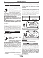
WORK CLIP LEAD
ELECTRIC SHOCK CAN KILL.
• ONLY QUALIFIED PERSONNEL
SHOULD PERFORM THIS
INSTALLATION.
• Do not touch metal portions of the
LN™-15 work clip lead when
the welding power source is on. The work clip
lead is electrically "hot" to work if the input
electrode cable to the LN™-15 is electrically
"hot", even if the gun trigger is off. Care should
be taken to only handle the LN™-15 work clip
lead by its nonmetal insulated portions and/or
the welding power source should be turned off
before handling the work clip.
• Do not attach the work clip lead to the roll cage
or bottom skids of the LN™-15.
• Attach the work clip only to the work piece.
-------------------------------------------------------------------
** The work clip lead is present only on Across-the-
Arc models.
The work clip lead attached to the front of the LN™-
15 must be connected directly to the work using the
spring clip on the end of the lead.
If the work clip lead is not connected, the LN™-15 will
not operate.
The work clip lead also serves as a work sensing lead
for the LN™-15. If the work clip lead is extended by
the user beyond the standard 15' (4.6m) length, the
voltmeter reading will be lower than the actual arc
volts due to resistance in the extended lead. To mini-
mize the error, the following lead size is recommend-
ed for the maximum extended lengths shown.
AWG Max. Length
#14 25 ft (7.6m)
#12 50 ft (15.2m)
#10 100 ft (30.5m)
#6 200 ft (61.0m)
CORRECT WORK CLIP ATTACHED TO WORK
INCORRECT WORK CLIP ATTACHED TO ROLL CAGE
HIGH FREQUENCY PROTECTION
To prevent possible damage to the LN™-15, do
not connect the LN™-15 to non-Lincoln TIG or
SQUARE WAVE power sources. TIG high frequen-
cy should never be applied to the LN™-15.
-------------------------------------------------------------------
Locate the LN™-15 away from radio controlled
machinery. The normal operation of the LN™-15 may
adversely affect the operation of RF controlled equip-
ment, which may result in bodily injury or damage to
the equipment total.
WARNING
WARNING
CAUTION

A-3
INSTALLATION
LN™-15 ACROSS THE ARC MODEL & (CE)
A-3
WELD CABLE CONNECTIONS
ELECTRIC SHOCK CAN KILL.
• Only a qualified electrician should
connect the electrode leads to the
LN™-15. Connections should be
made in accordance with all local
and national electrical codes.
Failure to do so may result in bodi-
ly injury or death.
-------------------------------------------------------------------
The size of the electrode cable and work cable must
be sufficient for the maximum weld current and total
cable length used.
To avoid interference problems with other equipment
and to achieve the best possible operation, route all
cables directly to the work or wire feeder. Avoid
excessive lengths and do not coil excess cable. Be
sure the connection to the work makes tight metal-to-
metal electrical contact. (See Table A.1)
ELECTRODE CONNECTION
Route the electrode cable through the strain relief in
the rear of the case. Connect the electrode cable to
the LN™-15 input stud using the mounting hardware
provided. Secure the cable by tightening the strain
relief.
All domestic models are supplied with pigtail for cus-
tomers that prefer to make a taped and bolted con-
nection externally. CE models have a male twist con-
nector for the electrode connection.
WORK CONNECTION
Connect a work lead of sufficient size between the
proper output stud on the power source and the work.
Be sure the connection to the work makes tight metal
to metal electrical contact. Poor work lead connec-
tions can result in poor welding performance.
POWER SOURCE CONNECTION
The LN™-15 can be used with any DC welding power
source. A constant voltage power source is recom-
mend; however, the LN™-15 can also be used with a
constant current power source as long as the open
circuit voltage is less than 110VDC.
To prevent possible damage to the LN™-15, do
not connect the LN™-15 to non-Lincoln TIG or
square wave power sources. TIG high frequency
should never be applied to the LN™-15.
------------------------------------------------------------------------------------------
WARNING
CAUTION
Weld Current Total Cable Length
60% Duty (electrode cable + work cable)
Cycle 50 - 100' 100 - 150' 150 - 200' 200 - 250'
(15-30 m) (30 - 46m) (46 - 61m) (61m - 76m)
200 Amps 2 AWG 2 AWG 1 AWG 1/0
300 Amps 1 AWG 1 AWG 1/0 2/0
400 Amps 2/0 2/0 3/0 3/0
TABLE A.1
ENGINE DRIVE POWER SOURCE
CONNECTION
The LN™-15 has an internal contactor and the elec-
trode is not energized until the gun trigger is closed.
When the gun trigger is closed the wire will begin to
feed and the welding process is started.
1. Shut the welder off.
2. For electrode Positive polarity welding, connect the
electrode cable to the "+" terminal of the welder
and work cable to the "-" terminal of the welder. For
Electrode Negative welding, connect the electrode
cable to the "-" terminal of the welder and work
cable to the "+" terminal of the welder.
3. Attach the work clip lead from the front of the LN™-
15 to work using the spring clip at the end of the
lead. This is a control lead to supply current to the
wire feeder motor; it does not carry welding current.
4. Set the MODE switch on the engine drive to CV-
WIRE.
5. Set the WELD TERMINALS switch to WELD TER-
MINALS ON.
6. Set the WIRE FEEDER VOLTMETER switch to
either "+" or "-" as required by the electrode polarity
being used.
7. Set the ARC CONTROL knob to "0" initially and
adjust to suit.
8. Set the IDLE switch to the AUTO position.
Important: Some older engine drives may require
the IDLE switch to be in the HIGH position for prop-
er LN™-15 operation.

A-4
INSTALLATION
LN™-15 ACROSS THE ARC MODEL & (CE)
A-4
Work
Clamp
Electrode Cable
Electrode Cable
Electrode Cable
Work
Clamp
Work
Clamp
wire feeder
K1870-1
wire feeder
K1870-1
RANGER 8
SAE 400 WITH CV ADAPTER
ENGINE DRIVEN WELDERS
WITH WIRE FEED MODULE
(LOCAL MODE AND CV ADAPTER)
CV250
CV300
CV400
CC POWER SOURCE
Output
Output T
erminals
erminals
Always Hot.
Always Hot.
Output
Output T
erminals
erminals
Always Hot.
Always Hot.
Output
Output T
erminals
erminals
Always Hot.
Always Hot.
Order K484 Jumper
Order K484 Jumper
Plug Kit.
Plug Kit.
Electrode Cable
Work
Clamp
semiautomatic
semiautomatic
semiautomatic
semiautomatic
wire feeder
K1870-1
wire feeder
K1870-1
wire feeder
K1870-1
CV655, DC400, DC600,
DC655, V350-PRO,
RANGER 9, RANGER 300 DLX
COMMANDER 300
COMMANDER 500
RANGER 250
RANGER 305G
Output
Output T
erminals
erminals
Always Hot.
Always Hot.
Power source contactor
Power source contactor
switch must be in the
switch must be in the
"ON" position or use a
"ON" position or use a
K848 Junper Plug Kit.
K848 Junper Plug Kit.
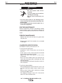
CONNECTION DIAGRAM, ACROSS THE ARC MODEL Set-Up ( See Figure A.1)
Typically used for general fabrication, maintenance and repair jobs because it’s easy to set up and operate.
Requires only one cable-less to carry. Contactor standard on Across The Arc Model.
FIGURE A.1
Although a constant voltage (CV) power source is recommended for best results with Innershield® and gas
metal arc (GMAW) open arc welding, satisfactory general purpose welding may be obtained using the LN™-15
with a constant current (CC) power source for non-critical commercial quality mild steel welding applications.

A-5
INSTALLATION
LN™-15 ACROSS THE ARC MODEL & (CE)
A-5
GUN AND CABLE ASSEMBLIES
A variety of Lincoln 10' (3.0m) or 15' (4.6m) gun and
cable assemblies are available for use with the LN™-
15, including the Magnum™ models for GMAW, K126
or K115 models for Innershield®.
The LN™-15 comes factory equipped with a K1500-2
gun connection kit, designed for guns having a
Magnum Tweco™ compatible #2-#4 connector. Many
other guns can easily be used with the LN™-15 with
other K1500 series gun connection kits.
Gun Cable Connection to the Feeder
Lay the cable out straight. Insert the connector on the
welding conductor cable into the brass bushing on the
front of the wire drive unit. Keep the all mating sur-
faces clean. Make sure it is fully seated and tighten
the thumb screw.
Connect the control cable plug into the 5 pin recepta-
cle on the front panel of the wire feeder.
ELECTRODE POLARITY
The LN™-15 automatically adjusts for positive and
negative polarity. When welding with negative polarity
procedures, the voltmeter will display a "-" sign; exam-
ple "-23.6" Volts.
CONNECTIONS
Across the Arc LN™-15 models do not use a control
cable.
Table A.2 Trigger Connector J1 (5 Pin)
PIN Lead # Function
A 556 Trigger
B - Not used
C 554 Trigger/ 83%
Procedure ground
D 555 83% Procedure
E 554 Trigger/ 83%
Procedure ground
PROCEDURE TO INSTALL DRIVE ROLLS
AND WIRE GUIDES
• Turn off input power at the weld-
ing power source before installa-
tion or changing drive roll and/or
wire guides.
• Do not touch electrically live parts such as the
wire drive or internal wiring.
• When feeding with the gun trigger, the electrode
and wire drive mechanism are "hot" to work and
ground and could remain energized several sec-
onds after the gun trigger is released.
• Only qualified personnel should perform this
operation.
-------------------------------------------------------------------
1. Turn OFF the welding power source.
2.
Open the LN™-15 case and then release the idle
roll pressure arm.
3. Remove the outer wire guide by turning the knurled
thumbscrews counter-clockwise to unscrew them
from the feed plate.
4. Rotate the triangular shaped drive roll retaining
mechanism to unlock the drive rolls and remove the
drive rolls.
5. Remove the inner wire guide.
6. Insert the new inner wire guide, groove side out,
over the two locating pins in the feed plate.
7. Install a drive roll on each hub assembly and lock
by rotating the triangular drive roll retaining mecha-
nism.
8. Install the outer wire guide by aligning it with the
pins and tightening the knurled thumbscrews.
9. Close the idle arm and engage the idle roll pressure
arm. Adjust the pressure appropriately.
WARNING

A-6
INSTALLATION
LN™-15 ACROSS THE ARC MODEL & (CE)
A-6
FEEDING WIRE ELECTRODE
• ELECTRIC SHOCK CAN KILL.
• When feeding electrode with the
gun trigger, the electrode and wire
drive mechanism are always "hot"
to work and ground and could
remain "hot" several seconds after
the gun trigger is released.
-------------------------------------------------------------------
1. Turn the reel or spool until the free end of the elec-
trode is accessible.
2.
While tightly holding the electrode, cut off the bent
end and straighten the first 6" (15 cm). Cut off the
first 1" (2.5 cm). If the electrode is not properly
straightened, it may not feed or may jam.
3. Insert the free end through the incoming guide
bushing.
4. Press the Cold Feed switch and push the electrode
into the drive roll.
5. Feed the electrode through the gun.
6. Adjust the brake tension with the thumbscrew on
the spindle hub, until the reel turns freely but with
little or no overrun when the wire feeding stops. Do
not overtighten.
WARNING
COLD FEED/
GAS PURGE
2 STEP/TRIGGER
INTERLOCK
SWITCH

B-1
OPERATION
LN™-15 ACROSS THE ARC MODEL & (CE)
B-1
• ELECTRIC SHOCK CAN KILL.
Unless using COLD FEED fea-
ture, when feeding with gun trig-
ger, the electrode and drive
mechanism are always electri-
cally energized and could
remain energized several sec-
onds after the welding ceases..
• Do not attach the work clip to the roll cage or
bottom skids. The work clip is energized any
time the output of the welding power source is
“ON”, even when the feeder is not welding.
• Do not touch electrically live part or electrode
with skin or wet clothing.
• Insulate yourself from work and ground.
• Always wear dry insulating gloves.
• The serviceability of a product or structure uti-
lizing the LN™-15 wire feeder is and must be
the sole responsibility of the builder/user. Many
variables beyond the control of The Lincoln
Electric Company affect the results obtained in
using the LN™-15 wire feeder. These variables
include, but are not limited to, welding proce-
dure, plate chemistry and temperature, weld-
ment design, fabrication methods and service
requirements. The available range of the LN™-
15 wire feeder may not be suitable for all appli-
cations, and the builder/user is and must be
solely responsible for welding settings.
-----------------------------------------------------------------
• FUMES AND GASSES can be
dangerous.
• Keep your head out of fumes.
• Use ventilation or exhaust at the
arc, or both, to remove fumes
and gases from breathing zone
and general area.
-----------------------------------------------------------------
• WELDING SPARKS can cause
fire or explosion.
• Keep flammable material away.
-----------------------------------------------------------------
ARC RAYS can burn.
• Wear eye, ear and body protec-
tion.
-----------------------------------------------------------------
SEE ADDITIONAL WARNING INFORMATION
UNDER ARC WELDING SAFETY PRECAUTIONS
AND IN THE FRONT OF THIS OPERATING MAN-
UAL.
-----------------------------------------------------------------
WARNING
SAFETY PRECAUTIONS
READ AND UNDERSTAND ENTIRE SECTION
BEFORE OPERATING MACHINE.
INPUT POWER
ON
OFF
WIRE FEEDER
POSITIVE OUTPUT
NEGATIVE OUTPUT
INPUT POWER
DIRECT CURRENT
OPEN CIRCUIT
VOLTAGE
INPUT VOLTAGE
OUTPUT VOLTAGE
INPUT CURRENT
OUTPUT CURRENT
PROTECTIVE
GROUND
WARNING OR
CAUTION
U
0
U
1
U
2
I
1
I
2
GRAPHIC SYMBOLS THAT APPEAR ON
THIS MACHINE OR IN THIS MANUAL

B-2
OPERATION
B-2
GENERAL DESCRIPTION
The LN™-15 is a light weight, portable, durable semi-
automatic wire feeder.
The LN™-15 accommodates spools 8" (200mm)
diameter up to 4" (100mm) wide.
The domestic feeders comes factory equipped with a
K1500-2 Magnum Tweco-compatible style #2-#4 gun
bushing. Other K1500 series gun bushings are avail-
able as field installed options. European models are
factory equipped with a Fast-Mate adapter.
The wire drive is capable of operating in either a "CV"
or "CC" mode. A constant voltage (CV) power source
is recommended for flux-cored arc welding (FCAW)
and gas metal arc welding (GMAW) to obtain code
quality results. However, the LN™-15 may also be
used with a constant current (CC) power source to
obtain passable results for non-critical quality applica-
tions.
The “dual procedure” mode drops the WFS to 83% of
the original set point. The voltage setting remains the
same.
• Burn-back is adjustable from 0.0 to 0.25 seconds,
with a default of 0.00 seconds.
• The preflow time is adjustable from 0.00 to 25.0 sec-
onds, with a default of 0.00 seconds.
• The postflow time is adjustable from 0.0 to 25.0 sec-
onds, with a default setting of 0.0 seconds.
The Across the Arc Model is capable of operating with
Lincoln DC power sources supplying between 15VDC
and 110 VDC. Simply attach the work clip to the work
piece and then connect the LN™-15 to the electrode
cable to the power source and it is ready to weld.
An internal contactor in Across the Arc Models ener-
gizes the electrode output in response to the gun trig-
ger.
LN™-15 ACROSS THE ARC MODEL & (CE)
DUTY CYCLE
The LN™-15 wire feeders are intended for semi-auto-
matic use. The maximum rating of the LN™-15 is
based upon a 60% duty cycle; welding 6 minutes of
welding followed by 4 minutes of idling within a 10
minute period.
RECOMMENDED PROCESSES
The LN™-15 wire drive feeds electrode for various
processes as follows:(See Table B.1)
The Across the Arc Model is suitable for GMAW,
GMAW-Pulse and FCAW semi-automatic applications
within the rated duty cycle.
PROCESS LIMITATIONS
• The across the arc model is not recommended for
spot or stitch welding.
• The across the arc model is not recommended for
GMAW-STT, SAW, SMAW, GTAW or CAG.
EQUIPMENT LIMITATIONS
Codes 10864, 10865
• The LN™-15 cannot be used with K489-7 Fast Mate
Gun receiver bushing or K1500-4 gun adapter bush-
ing.
Codes 11033 and higher
• The LN™-15 cannot be used with the K1500-4 gun
adapter bushing.
OPERATIONAL FEATURES AND
CONTROLS
• Built in flow meter for adjusting shielding gas.
• Cold Feed/Gas Purge switch.
• 2 step/Trigger Interlock switch (codes 11033 and
above only.)
• Digital wire feed speed control.
• Digital display of welding voltage.
• Adjustable preflow and postflow times
• Adjustable burnback times.
• On/Off switch (codes 11033 and above only.)
Process Wire Diameter Range Wire Feed Speed Range
GMAW 0.023 - 0.052" (0.6 - 1.3 mm) 50 - 700 ipm (1.3 - 17.8 m/minute)
FCAW 0.045 - 0.052" (1.2 - 1.3 mm) 50 - 700 ipm (1.3 - 17.8 m/minute)
FCAW 1/16 - 5/64" (1.6 - 2.0 mm) 50 - 400 ipm (1.3 - 10.2 m/minute)
TABLE B.1

B-3
OPERATION
B-3
LN™-15 ACROSS THE ARC MODEL & (CE)
1
2
3
4
5
6
7
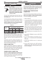
3. WIRE FEED SPEED KNOB-The Wire Feed Speed
knob is a 3-3/4 turn potentiometer that adjusts of
the rate of feeding electrode. The wire feed speed
range is 50 - 700 inches/min (1.3 - 17.8 m/min)
4. TRIGGER CONNECTOR-5 Pin Receptacle is used
to activate the Magnum Gun Switch.
5. CONNECTOR BUSHING-This connection is for
welding conductor cable assembly.
6. WORK CLIP LEAD-This lead must be connected
directly to the work using the spring clip.
7. ON / OFF SWITCH-For codes 11033 and above:
The ON / OFF Switch turns power on and off to the
wire feeder.
83% PROCEDURE
The LN™-15 supports a special "dual procedure"
mode. When activated, the wire feed speed is
reduced to 83% of the set value, but no less than 50
inches/minute (1.27 m/min). The 83% procedure is
most commonly used during pipe and out of position
welding. Requires Magnum 400 Dual Procedure Gun
Equivalent.
FIGURE B.1
CASE FRONT CONTROLS (See Figure B.1)
ACROSS THE ARC MODEL
1. WIRE FEED SPEED DISPLAY-The Wire Feed
Speed display shows the rate the LN™-15 will feed
electrode during welding. The default WFS units
for domestic models are inches/minute and can be
changed to meters/minute through the configuration
menu. The default WFS units for the European
models are m/min. The wire feed speed is calibrat-
ed to within ±2%.
2. VOLTAGE DISPLAY
-The voltage display shows
the average arc voltage during welding. A minus
sign "-" appears when welding with electrode nega-
tive welding procedures. While welding, an LED
will illuminate below the voltage display. After weld-
ing, the average voltage will continue to be shown
for 5 seconds after the end and the LED will flash.
of the weld. When not welding, the display shows
"- - - ". The voltage is calibrated to ±2% over a
range of 10 to 45 volts.
The voltage display is not a "preset" voltage.
Refer to the examples from Figure B.1a.
FIGURE B.1a

B-4
OPERATION
B-4
LN™-15 ACROSS THE ARC MODEL & (CE)
LN™-15 POWER-UP SEQUENCE
NORMAL POWER-UP DISPLAY
When power is first applied to the LN™-15, the dis-
play will momentarily show set-up information. For
example, it may show "CV" and "HI", indicating oper-
ation from a CV power source and the wire drive is
configured for the high speed gear. Because of limita-
tions in the display, "CV" will appear as "Cu".
After a brief moment, the LN™-15 will then display the
WFS and "---". No voltage is displayed until the trigger
is pressed.
PREFLOW, POSTFLOW AND BURNBACK TIMES
Preflow, Postflow and Burnback times are all
adjustable on the LN™-15. The LN™-15 is factory set
with all the times set to 0.0 seconds.
• The burnback time is adjustable from 0.00 to 0.25
seconds.
• The preflow time is adjustable from 0.0 to 25.0 sec-
onds.
• The postflow time is adjustable from 0.0 to 25.0 sec-
onds.
CHANGING PREFLOW, POSTFLOW OR BURNBACK TIMES:
1. Enter the “Press Spin” Set-Up Mode:
While the power to the LN™-15 is off, activate and
hold the GAS PURGE switch (Down Position).
Turn on power to the LN™-15, and continue to
hold the GAS PURGE switch until the LN™-15 dis-
plays "Press Spin". Release the GAS PURGE
switch. The LN™-15 is now in the "Press Spin" set-
up mode. If after 15 seconds no other action is
taken, the LN™-15 will then revert to normal oper-
ation.
2. Rotate the WFS knob until the desired timer is dis-
played.
Preflow:
Postflow:
Burnback:
3. Activate and then release the GAS PURGE switch
to select the timer. The time will then display in the
right hand side of the display. Example:
4. Rotate the WFS knob to adjust the time to the new
setting.
5. Press the GAS PURGE switch again to save the
setting. The LN™-15 will then return to the original
"Press Spin" mode in step 1.
6. To exit the "Press Spin" set-up mode, turn off power
to the LN™-15, or simply wait 15 seconds and the
LN™-15 will enter normal operation.
WELDING MODE CV/CC MODE AND WFS UNITS
The CV/CC mode and WFS units are all readily
changed during the power-up sequence. The LN™-15
is factory set for "CV" welding power sources and
"inches per minute" for the wire feed speed units.
• The CV/CC mode is selectable for either CV for
Constant Voltage power sources and CC for
Constant Current power sources. Use CV power
sources when making critical welds.
• The WFS units is selectable for either in/min and
m/min.
CHANGING THE CV/CC MODE, OR WFS UNITS:
1. Enter the “Press Spin” Set-Up Mode:
While the power to the LN™-15 is off, activate and
hold the GAS PURGE switch (Down Position). Turn
on power to the LN™-15, and continue to hold the
GAS PURGE switch until the LN™-15 displays
"Press spin". Release the GAS PURGE switch.
The LN™-15 is now in the "Press Spin" set-up
mode. If after 15 seconds no other action is taken,
the LN™-15 will then revert to normal operation.
COLD
FEED
GAS PURGE
COLD
FEED
GAS PURGE
WFS

SPRING TENSION ARM
The pressure arm controls the amount of force the drive
rolls exert on the wire. Proper adjustment of both pres-
sure arm gives the best welding performance. For best
results, set both pressure arms to the same value.
Set the pressure arm as follows (See Figure B.2a):
Aluminum wires between 1 and 3
Cored wires between 3 and 4
Steel, Stainless wires between 4 and 6
Figure B.2a
FLOWMETER
SPRING
TENSION
ARM
COLD FEED/
GAS PURGE
SWITCH
2 STEP/TRIGGER
INTERLOCK
SWITCH
SPINDLE
BRAKE
INTERNAL CONTROLS (Figure B.2)
B-5
OPERATION
B-5
LN™-15 ACROSS THE ARC MODEL & (CE)
Rotate the WFS knob until the desired parameter is
displayed.
CV/CC Mode:
WFS Units:
2. Activate and release the GAS PURGE switch to
select the parameter. The present value will then
display in the right hand side of the display.
Example:
3. Rotate the WFS knob to change the parameter set-
ting.
CV/CC MODE:
• "CU" for Constant Voltage power sources
• "CC" for Constant Current power sources
WFS UNITS:
• "US" for in/min
• "Eur" for m/min
4. Press the GAS PURGE switch to save the setting.
The LN™-15 will then return to the original "Press
Spin" mode in step 1.
5. To exit the "Press Spin" set-up mode, turn off power
to the LN™-15, or simply wait 15 seconds and the
LN™-15 will enter normal operation.
WFS
ALUMINUM
OU TE R S HI E L D
METAL SHIELD
IN NERS H IEL D
STEEL
STAINL E SS
CORED WIRES
SOLID WIRES
6
1
3
2
5
4
La page est en cours de chargement...
La page est en cours de chargement...
La page est en cours de chargement...
La page est en cours de chargement...
La page est en cours de chargement...
La page est en cours de chargement...
La page est en cours de chargement...
La page est en cours de chargement...
La page est en cours de chargement...
La page est en cours de chargement...
La page est en cours de chargement...
La page est en cours de chargement...
La page est en cours de chargement...
La page est en cours de chargement...
La page est en cours de chargement...
La page est en cours de chargement...
La page est en cours de chargement...
La page est en cours de chargement...
La page est en cours de chargement...
La page est en cours de chargement...
-
 1
1
-
 2
2
-
 3
3
-
 4
4
-
 5
5
-
 6
6
-
 7
7
-
 8
8
-
 9
9
-
 10
10
-
 11
11
-
 12
12
-
 13
13
-
 14
14
-
 15
15
-
 16
16
-
 17
17
-
 18
18
-
 19
19
-
 20
20
-
 21
21
-
 22
22
-
 23
23
-
 24
24
-
 25
25
-
 26
26
-
 27
27
-
 28
28
-
 29
29
-
 30
30
-
 31
31
-
 32
32
-
 33
33
-
 34
34
-
 35
35
-
 36
36
-
 37
37
-
 38
38
-
 39
39
-
 40
40


Lincoln Electric IM823-A Manuel utilisateur
- Catégorie
- Système de soudage
- Taper
- Manuel utilisateur
- Ce manuel convient également à
dans d''autres langues
- English: Lincoln Electric IM823-A User manual
Documents connexes
-
Lincoln Electric LN-15 Mode d'emploi
-
-
-
-
-
-
-
-
-