KitchenAid KFRU271VSS00 Guide d'installation
- Catégorie
- Barbecues
- Taper
- Guide d'installation
Ce manuel convient également à

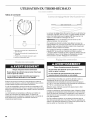
®itchen kid ®
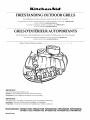
FREESTANDING OLUDOOR GRILLS
(;_IIIII(?
For questions about features, operation/performance, parts, accessories or service, call: 1-800-422-1230
or visit our website at www.kitchenaid.com
In Canada, for assistance, installation and service, call: 1-800-807-6777
or visit our website at www.KitchenAid.ca
P
GRILS D'EXTERIEUR AUTOPORTANTS
I[I,;_II_._.._.l(.lllSQ ll,;_llhlll(.ll ..........' ° .... ,,.,_._,............._..............=_,......
Au Canada, pourassistance,installationou servicecomposez le1-800-807-6777
ou visitez notre site Web &www.KitchenAid.ca
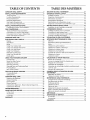
Table of Contents/Table des matieres ............................................................................. 4
iMPORTANT:
Save for local electrical inspector's use.
Jnstaler: Leave installation instructions with the homeowner.
Homeowner: Keep installation instructions for future reference.
iMPORTANT:
_, conserver pour consultation par I'inspecteur local des installations 61ectriques.
Instalateur : Remettre les instructions d'installation au propri6taire.
Propri6taire : Conserver les instructions d'installation pour r6f6rence ult6rieure.
Models/Modeles
W10175731A
KFRU271VSS, KFRU361VSS, KFRU365VSS, KFRU368VSS, KFRU488VSS,
KFRS271TSS, KFRS361TSS, KFRS365TSS, KFRU368TSS, KFRU488TSS

OUTDOOR GRILL SAFETY
Your safety and the safety of others are very important.
We have provided many important safety messages in this manual and on your appliance. Always read and obey all safety
messages.
This is the safety alert symbol.
This symbol alerts you to potential hazards that can kill or hurt you and others.
All safety messages will follow the safety alert symbol and either the word "DANGER" or "WARNING."
These words mean:
You can be killed or seriously injured if you don't immediately
follow instructions.
You can be killed or seriously injured if you don't follow
instructions.
All safety messages will tell you what the potential hazard is, tell you how to reduce the chance of injury, and tell you what can
happen if the instructions are not followed.
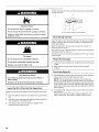
_b, DANGER
If you smell gas:
1. Shut off gas to the appliance.
2. Extinguish any open flame.
3. Open lid.
4. If odor continues, keep away from the
appliance and immediately call your
gas supplier or your fire department.
_, WARNING
1. Do not store or use gasoline or other
flammable liquids or vapors in the
vicinity of this or any other appliance.
2. An LP cylinder not connected for use
shall not be stored in the vicinity of
this or any other appliance.
State of California Proposition 65 Warnings:
WARNING: This product contains a chemical known to the State of California to cause cancer.
WARNING: This product contains a chemical known to the State of California to cause birth defects or other reproductive harm.
In the State of Massachusetts, the following installation instructions apply:
[] Installations and repairs must be performed by a qualified or licensed contractor, plumber, or gasfitter qualified or licensed by
the State of Massachusetts.
[] If using a ball valve, it shall be a T-handle type.
[] A flexible gas connector, when used, must not exceed 3 feet.
IMPORTANT: This grill is manufactured for outdoor use only. For grills that are to be used at elevations above 2000 ft (609.6 m) orifice
conversion is required. See "Gas Supply Requirements" section. It is the responsibility of the installer to comply with the minimum
installation clearances specified on the model/serial rating plate. The model/serial rating plate for freestanding models can be found on
the right-hand inside cabinet wall.
2

iMPORTANT SAFETY iNSTRUCTiONS
WARNING: To reduce the risk of fire, electrical shock,
injury to persons, or damage when using the outdoor cooking
gas appliance, follow basic precautions, including the
following:
[] Do not install portable or built-in outdoor cooking gas
appliances in or on a recreational vehicle, portable trailer,
boat or in any other moving installation.
[] Always maintain minimum clearances from combustible
construction, see "Location Requirements" section.
[] The outdoor cooking gas appliance shall not be located
under overhead unprotected combustible construction.
[] This outdoor cooking gas appliance shall be used only
outdoors and shall not be used in a building, garage, or any
other enclosed area.
[] Keep any electrical supply cord and fuel supply hose away
from any heated surfaces.
[] Keep outdoor cooking gas appliance area clear and free
from combustible materials, gasoline and other flammable
vapors and liquids.
[] Do not obstruct the flow of combustion and ventilation air.
Keep the ventilation openings of the cylinder enclosure free
and clear from debris.
[] Inspect the gas cylinder supply hose before each use of the
outdoor cooking gas appliance. If the hose shows
excessive abrasion or wear, or is cut, it MUST be replaced
before using the outdoor cooking gas appliance. Contact
your dealer and use only replacement hoses specified for
use with the outdoor cooking gas appliance.
[] Visually check the burner flames. They should be blue.
Slight yellow tipping is normal for LP gas.
[] Check and clean burner/venturi tube for insects and insect
nest. A clogged tube can lead to fire under the outdoor
cooking gas appliance.
SAVE THESE
[] The LP gas supply cylinder to be used must be:
- constructed and marked in accordance with the
Specification for LP Gas Cylinders of the U.S. Department
of Transportation (DOT) or the National Standard of
Canada, CAN/CSA-B339, Cylinders, Spheres, and Tubes
for Transportation of Dangerous Goods; and Commission.
- provided with a listed overfilling prevention device.
- provided with a cylinder connection device compatible
with the connection for outdoor cooking gas appliances.
[] Always check connections for leaks each time you connect
and disconnect the LP gas supply cylinder. See
"Installation Instructions" section.
[] When the outdoor cooking gas appliance is not in use, the
gas must be turned off at the supply cylinder.
[] Storage of an outdoor cooking gas appliance indoors is
permissible only if the cylinder is disconnected and
removed from the outdoor cooking gas appliance.
[] Cylinders must be stored outdoors and out of the reach of
children and must not be stored in a building, garage, or
any other enclosed area.
[] The pressure regulator and hose assembly supplied with
the outdoor cooking gas appliance must be used. A
replacement pressure regulator and hose assembly
specific to your model is available from your outdoor
cooking gas appliance dealer.
[] Gas cylinder must include a collar to protect the cylinder
valve.
[] For appliances designed to use a CGA791 Connection:
Place a dust cap on cylinder valve outlet whenever the
cylinder is not in use. Only install the type of dust cap on
the cylinder valve outlet that is provided with the cylinder
valve. Other types of caps or plugs may result in leakage
of propane.
If the following information is not followed exactly, a fire
causing death or serious injury may occur.
[] Do not store a spare LP gas cylinder under or near this
outdoor cooking gas appliance.
[] Never fill the cylinder beyond 80 percent full.
iNSTRUCTiONS

TABLEOF CONTENTS
OUTDOOR GRILL SAFETY ............................................................ 2
INSTALLATION REQUIREMENTS ................................................ 5
Tools and Parts ............................................................................ 5
Location Requirements ................................................................ 5
Product Dimensions .................................................................... 6
Electrical Requirements ............................................................... 6
Gas Supply Requirements ........................................................... 7
Gas Connection Requirements .................................................... 7
INSTALLATION INSTRUCTIONS .................................................. 9
Freestanding Outdoor Grill Installation ........................................ 9
GAS CONVERSIONS .................................................................... 14
Tools and Parts for Gas Conversion .......................................... 14
Conversion to a Local LP Gas Supply ....................................... 15
Conversion from LP Gas to Natural Gas ................................... 16
Check and Adjust the Burners ................................................... 19
OUTDOOR GRILL USE ................................................................ 20
ELECTRONIC GRILL DISPLAY ................................................... 20
Display ........................................................................................ 20
Start/Reset ................................................................................. 20
Mode .......................................................................................... 20
Using Your Outdoor Grill ............................................................ 22
Using Your Infrared Sear Burner ................................................ 23
Using Your Side Burner ............................................................. 23
Using Your Rotisserie ................................................................. 24
Rotisserie Cooking Tips ............................................................. 26
Using Your Smoker Box ............................................................ 27
Hood Lights ................................................................................ 27
USING YOUR WARMING DRAWER ........................................... 27
Control Knob .............................................................................. 27
Moist-Dry Slide Control .............................................................. 28
Setting the Controls ................................................................... 28
Warming Cookware ................................................................... 29
Warming Pans and Positioning Rack ........................................ 29
Proofing Bread ........................................................................... 29
Slow Cook Function ................................................................... 29
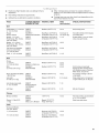
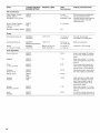
TIPS FOR OUTDOOR GRILLING ................................................ 30
Cooking Methods ....................................................................... 30
Grilling Chart............................................................................... 31
OUTDOOR GRILL CARE ............................................................. 33
Replacing the Batteries .............................................................. 33
General Cleaning ........................................................................ 34
Drawer Slides ............................................................................. 36
Drawer Removal ......................................................................... 36
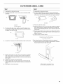
Cabinet Door Alignment - Style 2 (internal hinge) Only ............. 37
Cabinet Door Removal ............................................................... 37
TROUBLESHOOTING .................................................................. 38
ASSISTANCE OR SERVICE ......................................................... 39
In the U.S.A................................................................................ 39
Accessories ................................................................................ 39
In Canada ................................................................................... 39
WAR RANTY .................................................................................. 40
TABLE DES MATIERES
SI_CURITI_ DU GRIL D'EXTI_RIEUR ........................................... 41
EXIGENCES D'INSTALLATION ................................................... 43
Outillage et pieces ...................................................................... 43
Exigences d'emplacement ......................................................... 43
Dimensions du produit .............................................................. 44
Specifications electriques .......................................................... 44
Specifications de I'alimentation en gaz ..................................... 45
Exigences concernant le raccordement au gaz ........................ 46
INSTRUCTIONS D'INSTALLATION ............................................. 47
Installation du gril d'exterieur autoportant ................................. 47
CONVERSIONS DE GAZ .............................................................. 52
Outillage et pieces pour la conversion ....................................... 52
Conversion au gaz propane local .............................................. 53
Conversion de gaz propane & gaz naturel ................................. 54
Contr61e et reglage des brQleurs................................................ 57
UTILISATION DU GRIL D'EXTI_RIEUR ....................................... 58
AFFICHEUR I_LECTRONIQUE DU GRIL .................................... 59
Afficheur ..................................................................................... 59
Start/Reset (demarrage/r6initialisation) ...................................... 59
Mode ........................................................................................... 59
Utilisation du gril d'exterieur ....................................................... 60
Utilisation du brQleur & infrarouge .............................................. 62
Utilisation du brQleur lateral........................................................ 62
Utilisation du tournebroche ........................................................ 63
Conseils de cuisson & I'aide du tournebroche .......................... 64
Utilisation du fumoir ................................................................... 65
Lampes du capot ....................................................................... 65
UTILISATION DU TIROIR-RI_CHAUD ......................................... 66
Bouton de commande ............................................................... 66
Curseur de reglage Moist-Dry (humide-sec) .............................. 66
Reglage des commandes .......................................................... 66
Ustensiles de rechauffage .......................................................... 67
Ustensiles de rechauffage et grille de positionnement .............. 67
Levee du pain ............................................................................. 68
Fonction de cuisson lente .......................................................... 68
CONSEILS POUR L'UTILISATION DU GRIL
D'EXTI_RIEUR .............................................................................. 68
Methodes de cuisson ................................................................. 69
Tableau de cuisson au gril ......................................................... 70
ENTRETIEN DU GRIL D'EXTI_RIEUR ......................................... 72
Changement de I'ampoule d'eclairage ...................................... 72
Remplacement des piles ............................................................ 72
Nettoyage gen6ral ...................................................................... 73
Glissieres de tiroir ....................................................................... 75
Depose du tiroir .......................................................................... 75
Alignement de la porte du placard -
Style 2 (charniere interne) uniquement ...................................... 76
Depose de la porte du placard .................................................. 76
DI_PANNAGE ................................................................................. 77
ASSISTANCE OU SERVICE ......................................................... 78
Au Canada .................................................................................. 78
Accessoires ................................................................................ 78
GARANTIE ..................................................................................... 79

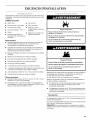
INSTALLATION REQUIREMENTS
asd Pa s
Gather the required tools and parts before starting installation.
Read and follow the instructions provided with any tools listed
here.
Tools Needed
• Tape measure •
• Small, flat-blade screwdriver •
• Flat-blade screwdriver •
• #2 and #3 Phillips screwdriver
• Level •
• Short Phillips screwdriver or a
90 ° screwdriver with a Phillips
screw bit
Wrench or pliers
Pipe wrench
Scissors or cutting pliers
(to remove tiedowns)
Noncorrosive leak-
detection solution
Parts Supplied
• Gas pressure regulator/hose assembly set for 11" WCP LP
gas (attached to manifold)
• Natural gas conversion kit with convertible regulator set for 4"
WCP Natural gas (on some models)
• Natural gas conversion kit (on some models)
• Rotisserie motor mounting bracket (on some models)
• Rotisserie motor (on some models)
• Rotisserie forks (on some models)
• Rotisserie spit (on some models)
• Smoker box (on some models)
• 2 warming drawer pans (on some models)
• 1 single-prong plug/500 mAmp transformer assembly for the
rotisserie motor (on some models)
• 2 - 1.5 V "D" size alkaline batteries (on some models)
• Vinyl grill cover (on some models)
Parts Needed
• 20 Ib LP gas fuel tank - approximately 18" (45.7 cm) height
and 12" (30.5 cm) diameter
• UL outdoor-rated 120 V extension cord - size 14 gauge/3 wire
(marked 14/3 W-A), 50 foot (15.2 m) maximum length
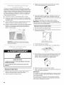
Explosion Hazard
Do not store fuel tank in a garage or indoors.
Do not store grill with fuel tank in a garage or indoors.
Failure to follow these instructions can result in death,
explosion, or fire.
Fire Hazard
Do not use grill near combustible materials.
Do not store combustible materials near grill.
Doing so can result in death or fire.
Select a location that provides minimum exposure to wind and
traffic paths. The location should be away from strong draft
areas.
Do not obstruct flow of combustion and ventilation air.
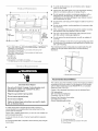
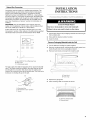
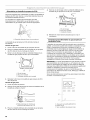
Clearance to combustible construction for freestanding outdoor
grills:
• A minimum of 24" (58 cm) must be maintained between the
front of the grill hood, sides and back of the grill and any
combustible construction.
• A 24" (58 cm) minimum clearance must also be maintained
below the cooking surface and any combustible construction.
Rotisserie
A 6" (15.2 cm) minimum clearance is needed for the rotisserie
motor.
A grounded, 3-prong outdoor outlet is located on the back of the
grill. See "Electrical Requirements" section.
NOTE: The rotisserie is an accessory on some models. See the
"Assistance or Service" section to order.

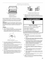
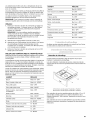
A
17W'
cm)
..... :T;,
,,"_T..................... _,,
f i
L t
B
17W'
(43.8 cm)
62%"
(158.7 crn)
50W'
(127.2 cm)
@ @_@@@@
28Vd'
(72.4 crn)
front of
handle to
back of grimm
A. 61 V2"(156.2 cm) on 27" (68.6 cm) models KFRS2 71T and KFRU2 71V
70Y2"(179.1 cm) on 36" (91.4 em) models KFRS361 T,KFRU361 V,
KFRS365T and KFRU365V
84Y2" (214.6 em) on 36" (91.4 em) models with side burner -
KFRU368T and KFRU368V
96Y2" (245.1 em) on 48" (121.9 em) models with side burner -
KFRU488T and KFRU488V
B. 27" (68.6 em)
36" (91.4 cm)
48" (121.9 cm)
C. Not available on 27" (68.6 cm) models
14" (35.6 cm) on 36" (91.4 cm) and 48" (121.9 cm) models
To avoid electrical shock, do not immerse cord or plugs in
water or other liquid.
Unplug from the outlet when not in use and before cleaning.
Allow to cool before putting on or taking off parts.
Do not operate any outdoor cooking gas appliance with a
damaged cord, damaged plug, or after the appliance
malfunctions or has been damaged in any manner. Contact
the manufacturer for repair.
Do not let the cord hang over the edge of a table or touch hot
surfaces.
• Do not use an outdoor cooking appliance for purposes other
than intended.
When connecting, first connect plug to the outdoor cooking
gas appliance then plug appliance into the outlet.
Use only a Ground Fault Interrupter (GFI) protected circuit
with this outdoor cooking gas appliance.
Do not remove the ground prong or use with an adapter of
2 prongs.
Use only extension cords with a 3 prong grounding plug rated
for the power of the equipment and approved for outdoor use
with a W-A marking.
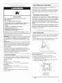
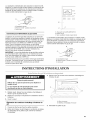
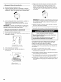
The model/serial number rating plate is located inside the grill
cabinet on the right-hand cabinet side. See the following
illustration.
A
x.@:?I_,. :*@?__.@ ?_I't:,,,
Electrical Shock Hazard
Use only a UL listed, 14 gauge, 3 wire extension cord
approved for outdoor use, marked W=A, with a
maximum length of 50 ft.
Plug into a grounded 3 prong outlet.
Do not remove ground prong.
Do not use an adapter.
Failure to follow these instructions can result in death,
fire, or electrical shock.
If codes permit and a separate ground wire is used, it is
recommended that a qualified electrician determine that the
ground path is adequate.
Check with a qualified electrician if you are not sure whether the
grill is properly grounded.
A 120-volt, 60-Hz, AC-only, 15-amp, fused electrical supply is
required.
It is recommended that a separate circuit servicing only this grill
be provided.
A. Model/serial number plate
Recommended Ground Method
The outdoor grill, when installed, must be electrically grounded in
accordance with local codes or, in the absence of local codes,
with the National Electrical Code ANSI/NFPA 70, or Canadian
Electrical Code, CSA C22.1.
Copies of the standards listed above may be obtained from:
CSA International
8501 East Pleasant Valley Rd.
Cleveland, Ohio 44131-5575
National Fire Protection Association
One Batterymarch Park
Quincy, Massachusetts 02269
S ............................
A.3-prong ground plug
B.3-prong polarized type outdoor GFI outlet
C. Ground prong
6

Explosion Hazard
Use a new CSA International approved "outdoor"
gas supply line.
Securely tighten all gas connections.
if connected to LP, have a qualified person make sure
gas pressure does not exceed 11" (28 cm) water
column.
Examples of a qualified person include:
licensed heating personnel,
authorized gas company personnel, and
authorized service personnel.
Failure to do so can result in death, explosion, or fire.
Observe all governing codes and ordinances.
IMPORTANT: This installation must conform with all local codes
and ordinances. In the absence of local codes, installation must
conform with American National Standard, National Fuel Gas
Code ANSI Z223.1 - latest edition or CAN/CGA B149.1 - latest
edition.
IMPORTANT: Grill must be connected to a regulated gas supply.
Refer to the model/serial rating plate for information on the type
of gas that can be used. If this information does not agree with
the type of gas available, check with your local gas supplier.
Gas Conversion:
No attempt shall be made to convert the grill from the gas
specified on the model/serial rating plate for use with a different
gas type without consulting the serving gas supplier. The
conversion kit supplied with grill must be used. See "Gas
Conversions" section for instructions.
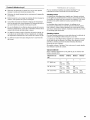
Gas Pressure Regulator
The gas pressure regulator supplied with this grill must be used.
The inlet (supply) pressure to the regulator should be as follows
for proper operation:
LP Gas:
Operating pressure: 11" (27.9 cm) WCP
Inlet (supply) pressure: 11" to 14" (27.9 cm to 35.5 cm) WCP
Natural Gas:
Operating pressure: 4" (10.2 cm) WCP
Inlet (supply) pressure: 7" to 14" (17.8 cm to 35.5 cm) WCP
maximum.
Contact local gas supplier if you are not sure about the inlet
(supply) pressure.
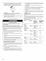
Burner Requirements for High Altitude
Input ratings shown on the model/serial rating plate are for
elevations up to 2,000 ft (609.6 m).
For elevations above 2,000 ft (609.6 m), ratings are reduced at a
rate of 4% for each 1,000 ft (304.8 m) above sea level. Orifice
conversion is required. See "Assistance or Service" section to
order.
Gas Supply Line Pressure Testing
Testing above 1/2psi (3.5 kPa) or 14" (35.5 cm) WCP (gauge):
The grill and its individual shutoff valve must be disconnected
from the gas supply piping system during any pressure testing of
that system at test pressures greater than 1/2psi (3.5 kPa).
Testing below 1/2psi (3.5 kPa) or 14" (35.5 cm) WOP (gauge) or
lower:
The grill must be isolated from the gas supply piping system by
closing its individual manual shutoff valve during any pressure
testing of the gas supply piping system at test pressures equal to
or less than 1/2psi (3.5 kPa).
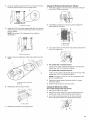
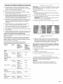
20 Ib LP Gas Fuel Tank
This grill is equipped for use with a 20 Ib LP gas fuel tank (fuel
tank not supplied). A gas pressure regulator/hose assembly is
supplied.
It is also design-certified by CSA International for local LP gas
supply or for Natural gas with appropriate conversion.
\
A. Gaspressure regulator/hose assembly
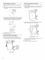
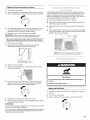
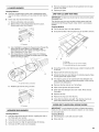
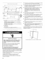
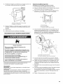
The 20 Ib LP gas fuel tank must be mounted and secured.
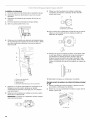
Drawer Style Tank Tray
1. Open the drawer for the 201b LP gas fuel tank.
2. Place the 20 Ib LP gas fuel tank bottom collar into the
mounting hole in the tank tray.
3. Tighten the locking screw against the bottom collar of the
20 Ib LP gas fuel tank to secure.
A , _
B C
A. Locking screw
B.Mounting hole
C. Bottom coflar
4. Slide the drawer with the 201b LP gas fuel tank back into the
cabinet.

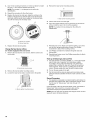
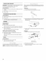
DoorStyleTankTray
1. Opencabinetdoors.
2. Pressthelockingtabonthetanktrayandpulloutthetray.
A
A. 20 Ib LP gas fuel tank tray locking tab
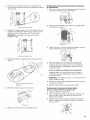
3. Place the 20 Ib LP gas fuel tank bottom collar into the
mounting hole in the tank tray.
4. Tighten the locking screw against the bottom collar of the
20 Ib LP gas fuel tank to secure.
B C
A. Locking screw
B. Mounting hole
C. Bottom collar
5. Slide the tank tray back into the cabinet and lock into place.
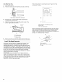
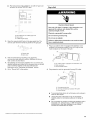
Local LP Gas Supply Conversion
Conversion must be made by a qualified gas technician. The
qualified gas technician shall provide the gas supply to the
selected grill location in accordance with the National Fuel Gas
Code ANSI Z223.1/NFPA 54 - latest edition, and local codes. For
conversion to local LP,the convertible regulator in the conversion
kit supplied with the grill (on some models) must be used. Models
that do not come with the conversion kit require Convertible
Regulator Part Number W10132702. See "Assistance or Service"
section for information on ordering.
IMPORTANT: The gas installation must conform with local
codes, or in the absence of local codes, with the National Fuel
Gas Code, ANSI Z223.1/NFPA 54 - latest edition. The qualified
LP gas technician shall provide the LP gas supply to the selected
grill location in accordance with the National Fuel Gas Code,
ANSI Z223.1/NFPA 54 and local codes.
Follow instructions for converting to local LP gas in the "Gas
Conversions" section.
<, _> < ,
S .............................................................
_0
A. New ANSI Z21.54 certified gray hose
B. Rear of grill
C. To local LP gas supply
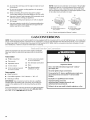
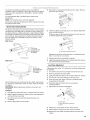
The gas supply line shall be equipped with an approved shutoff
valve. This valve should be located in the same area as the grill
and should be in a location that allows ease of opening and
closing. Do not block access to the shutoff valve. The valve is for
turning on or shutting off gas to the grill.
B
X
C/
A. Gas supply line
B. Shutoff valve "open" position
C. To grill
8

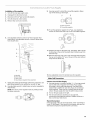
Natural Gas Conversion
Conversion must be made by a qualified gas technician. The
qualified Natural gas technician shall provide the Natural gas
supply to the selected grill location in accordance with the
National Fuel Gas Code ANSI Z223.1/NFPA 54 - latest edition,
and local codes. For conversion to Natural gas, the Natural Gas
Conversion Kit supplied with the grill (on some models) or the
Natural Gas Conversion Kit Part Number W10118098 must be
used. See "Assistance or Service" section for information on
ordering.
IMPORTANT: The gas installation must conform with local
codes, or in the absence of local codes, with the National Fuel
Gas Code, ANSI Z223.1/NFPA 54 - latest edition.
Follow instructions for converting to Natural gas in the "Gas
Conversions" section of this manual or the instructions supplied
with Natural Gas Conversion Kit Part Number W10118098.
INSTALLATION
INSTRUCTIONS
():/ (}4}_
Excessive Weight Hazard
Use two or more people to move and install grill.
Failure to do so can result in back or other injury.
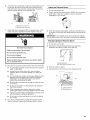
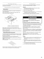
1. Unpack grill. Remove all packaging materials and remove grill
from wooden skid.
2. Move grill into desired outdoor location.
3. Open the hood.
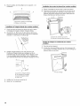
Remove Packaging Material Inside the Grill
1. Cut the tiedowns holding the grates together.
2. Remove condiment shelf, warming shelf and grill grates from
inside the grill and remove packaging material.
3. Remove foam block and wrap from inside the grill.
A. New ANSI Z21.54 certified gray hose
B.Rear of grill
C. To Natural gas supply
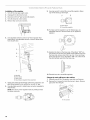
The gas supply line shall be equipped with an approved shutoff
valve. This valve should be located in the same area as the grill
and should be in a location that allows ease of opening and
closing. Do not block access to the shutoff valve. The valve is for
turning on or shutting off gas to the grill.
A
B
A. Gas supply line
B. Shutoff valve "open" position
C. To grill
4.
5.
A ..........
,/ •
.......... _ //i;::_B
\
A. Foam block
B.Foam wrap
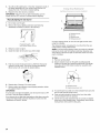
Replace the grill grates.
Place warming shelf on brackets as shown.
B
A A
A. Warming shelf brackets
B. Warming shelf

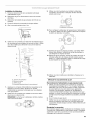
Attach Side Shelf (on some models)
1. Open doors below grill and remove carton. Unpack side
shelf.
2. Locate 4 screws. Install 2 screws in the top 2 holes on each
side of the grill. Leave screws away from side of grill about
1_,,(0.64 cm).
3=
Install side shelf on left side of the grill. Position the side shelf
so that the large end of the keyhole slots are over the screws.
Place shelf onto the 2 mounting screws. Let the shelf slide
down so the screws are in the narrow neck of the slots.
A .....................
B
A. Top of side shelf
B. Keyhole slot
C. Front of side shelf
D. Side of grifl
4. Install the bottom 2 screws and tighten.
5. Tighten the top 2 screws.
Attach Cabinet Doors (on some models)
1. Remove foam wrapping from both cabinet doors.
2. Position hinge pins on the door with the hinge brackets on
the cabinet. Gently push down to slide the pins into place.
\
\
A
A. Door hinge pin
B. Hinge bracket
Attach Condiment Shelf (on some models)
1. Open cabinet door.
2. Use a short Phillips screwdriver or a 90 °screwdriver with a
Phillips screw bit to loosen the 2 mounting screws on the
inner door panel.
3=
A
A. Mounting screws
Position the condiment shelf so that the large ends of the
keyhole slots are over the 2 mounting screws.
4=
5.
6.
B
A.Mounting screw in keyholeslot
B.Condiment shelf
Lower the condiment shelf until the 2 mounting screws are in
the narrow ends of the keyhole slots.
Tighten the screws.
Dispose of/recycle all packaging material.
10

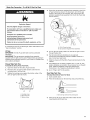
Make Gas Connection - To a 20 Ib LP Gas Fuel Tank
4.
Explosion Hazard
Securely tighten all gas connections.
if connected to LP, have a qualified person make sure
gas pressure does not exceed 11" (28 cm) water
column.
Examples of a qualified person include:
licensed heating personnel,
authorized gas company personnel, and
authorized service personnel.
Failure to do so can result in death, explosion, or fire.
If converting to local LP or Natural gas, follow instructions in the
"Gas Conversions" section.
LP Gas:
IMPORTANT: A 20 Ib LP gas fuel tank must be purchased
separately.
IMPORTANT: The gas pressure regulator/hose assembly
supplied with the grill must be used. Replacement gas pressure
regulator/hose assembly specific to your model, is available from
your outdoor grill dealer.
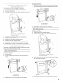
Drawer Style Tank Tray
To Install the 20 Ib LP Gas Fuel Tank:
1. Open the drawer for the 201b LP gas fuel tank.
2. Place the 20 Ib LP gas fuel tank bottom collar into the
mounting hole in the tank tray
3. Tighten the locking screw against the bottom collar of the
20 Ib LP gas fuel tank to secure.
A
B C
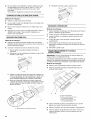
Screw the gas pressure regulator/hose assembly to the 20 Ib
LP gas fuel tank as shown. (To disconnect, turn off the gas
supply to the 20 Ib LP gas fuel tank, then unscrew the gas
pressure regulator/hose assembly from the 20 Ib LP gas fuel
tank as shown.)
B
A. 20 Ib LP gas fuel tank
B. Gaspressure regulator/hose assembly
5. Turn on the gas supply. Wait a few minutes for gas to move
through the gas line.
6. Test all connections by brushing on an approved
noncorrosive leak-detection solution. Bubbles will show a
leak. Correct any leak found.
7. Slide the drawer with the 201b LP gas fuel tank back into the
cabinet.
8. The batteries are not factory installed. The 1.5-volt "D" size
alkaline batteries are located in the accessory box on the grill
grate. Install the batteries at this time following the
instructions in the "Replacing the Batteries" section.
9. Go to "Plug in Grill" in this section.
Door Style Tank Tray
To Install the 20 Ib LP Gas Fuel Tank:
1. Open cabinet doors.
2. Press the locking tab on the tank tray and pull out the tray..
A. Locking screw
B. Mounting hole
C. Bottom collar
A. 20 Ib LP gas fuel tank tray locking tab
3. Place the 20 Ib LP gas fuel tank bottom collar into the
mounting hole in the tank tray.
11

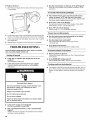
4. Tighten the locking screw against the bottom collar of the
20 Ib LP gas fuel tank to secure.
5=
B C
A. Locking screw
B. Mounting hole
C. Bottom collar
Screw the gas pressure regulator/hose assembly to the 20 Ib
LP gas fuel tank as shown. (Todisconnect, turn off the gas
supply to the 20 Ib LP gas fuel tank, then unscrew the gas
pressure regulator/hose assembly from the 20 Ib LP gas fuel
tank as shown.
A. 20 Ib LP gas fuel tank
B.Gaspressure regulator/hose assembly
6. Turn on the gas supply. Wait a few minutes for gas to move
through the gas line.
7. Test all connections by brushing on an approved
noncorrosive leak-detection solution. Bubbles will show a
leak. Correct any leak found.
8. Slide the tank tray back into the cabinet and lock into place.
9. The batteries are not factory installed. The 1.5-volt "D" size
alkaline batteries are located in the accessory box on the grill
grate. Install the batteries at this time following the
instructions in the "Replacing the Batteries" section.
10. Go to "Plug in Grill" in this section.
Gas Connection to Natural Gas or Local LP Gas
Explosion Hazard
Use a new CSA International approved "outdoor"
gas supply line.
Securely tighten all gas connections.
if connected to LP, have a qualified person make sure
gas pressure does not exceed 11" (28 cm) water
column.
Examples of a quaJified person include:
licensed heating personnel,
authorized gas company personnel, and
authorized service personnel.
Failure to do so can result in death, explosion, or fire.
This installation must conform with local codes and ordinances.
In the absence of local codes, installations must conform with
either the National Fuel Gas Code ANSI Z223.1, or CAN/CGA-
B149.1 Natural Gas and Propane installation code.
Copies of the standards listed above may be obtained from:
CSA International
8501 East Pleasant Valley Rd.
Cleveland, Ohio 44131-5575
National Fire Protection Association
One Batterymarch Park
Quincy, Massachusetts 02269
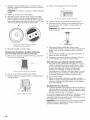
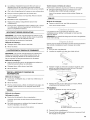
1. Make gas connections.
A combination of pipe fittings must be used to connect the
grill to the existing gas line.
• If local codes permit, use an outdoor flexible stainless
steel tubing gas connector, design-certified by CSA
International, to connect the grill to the rigid gas supply
line. A 5/8"diameter line is recommended. Using a wrench
to tighten, connect the gas supply to the grill. Use pipe-
joint compound on all non-flared male threads. Do not
kink or damage the flexible connector when moving the
grill.
12

• Pipe-joint compounds suitable for use with LP gas must
be used. Do not use TEFLON ®ttape. Plug in Grill
2=
A
J
C ........ !! .......................
A. New ANSI Z21.54 certified gray hose
B. Rear of grill
C. To Natural gas supply
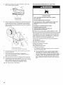
Open the manual shutoff valve in the gas supply line. The
valve is open when the handle is parallel to the gas pipe.
A. Closed valve
B. Open valve
3. Test all connections by brushing on an approved
noncorrosive leak-detection solution. Bubbles will show a
leak. Correct any leak found.
4. The batteries are not factory installed. The 1.5-volt "D" size
alkaline batteries are located in the accessory box on the grill
grate. Install the batteries at this time following the
instructions in the "Replacing the Batteries" section.
5. Go to "Plug in Grill" in this section.
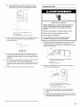
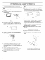
1=
Electrical Shock Hazard
Use only a UL listed, 14 gauge, 3 wire extension cord
approved for outdoor use, marked W=A, with a
maximum length of 50 ft.
Plug into a grounded 3 prong outlet.
Do not remove ground prong.
Do not use an adapter.
Failure to follow these instructions can result in death,
fire, or electrical shock.
Plug a UL outdoor rated 14 gauge/3 wire extension cord
(marked W-A) (maximum length 50 foot [15.2 m]) into the
male receptacle on the back of the grill.
B
A. UL outdoor rated 14 gauge/3 wire extension cord
B.Male receptacle
C. Circuit breaker button
2. Plug extension cord into grounded 3-prong GFI outlet.
S ...............................
A .... ".....................
A. 3-prong ground plug
B. 3-prong polarized type outdoor GFI outlet
C. Ground prong
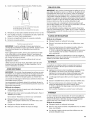
To avoid electrical shock, do not immerse cord or plugs in
water or other liquid.
Unplug from the outlet when not in use and before
cleaning. Allow to cool before putting on or taking off
parts.
Do not operate any outdoor cooking gas appliance with a
damaged cord, damaged plug, or after the appliance
malfunctions or has been damaged in any manner.
Contact the manufacturer for repair.
t®TEFLON is a registered trademark of E.I. Du Pont De Nemours and Company.
13

Do not let the cord hang over the edge of a table or touch
hot surfaces.
Do not use an outdoor cooking appliance for purposes
other than intended.
When connecting, first connect plug to the outdoor
cooking gas appliance then plug appliance into the outlet.
Use only a Ground Fault Interrupter (GFI) protected circuit
with this outdoor cooking gas appliance.
Do not remove the ground prong or use with an adapter
of 2 prongs.
Use only extension cords with a 3 prong grounding plug
rated for the power of the equipment and approved for
outdoor use with a W-A marking.
NOTE: Check the circuit breaker on the back of the grill after
plugging the grill into a 3-prong polarized type outdoor GFI
outlet if there is a loss of electrical power to the grill. Reset
the circuit breaker if the button is in the tripped position. Push
in the rubber boot and button to reset.
B
A. Rubber boot
B. Circuit breaker button in
"set" position
B
A. Rubber boot
B. Circuit breaker button
in "tripped" position
3. Go to "Check and Adjust the Burners" section
GAS CONVERSIONS
NOTE: These instructions are for grill models that come equipped with the conversion kit for Local LP and Natural gas. For models that
do not come equipped with the conversion kit: for conversion to Local LP order Regulator Part Number W10132702, or for conversion
to Natural gas order LP to Natural Gas Conversion Kit Part Number W10118098. Use the conversion instructions included in the kit.
See "Assistance or Service" section for information on ordering.
Gather the required tools and parts before starting installation.
Read and follow the instructions provided with any tools listed
here.
Tools needed
• Phillips screwdriver
• Pipe wrench
• Adjustable wrench
• 10 mm wrench
• 6 mm socket and wrench
or 6 mm nut driver
• 10 mm socket and wrench
or 10 mm nut driver
• Thin flat-blade screwdriver
• Pliers
• Pipe thread sealant
certified for LP gas
Parts supplied
• Brass connector
• Convertible regulator 4" W.C. Natural, 11" W.C. LP
• Natural gas orifices
IMPORTANT: Gas conversions must be done by a qualified
installer. Before proceeding with conversion, shut off the gas
supply to the appliance prior to disconnecting the electrical
power.
This kit is designed for use from sea level up to 2000 ft elevation.
For higher elevations contact KitchenAid at 1-800-422-1230 in
the U.S.A. or call 1-800-607-6777 in Canada.
Explosion Hazard
Use a new CSA international approved "outdoor"
gas supply line.
Securely tighten all gas connections.
ifconnected to LP, have a qualified person make sure
gas pressure does not exceed 11" (28 cm) water
column.
Examples of a qualified person include:
licensed heating personnel,
authorized gas company personnel, and
authorized service personnel.
Failure to do so can result in death, explosion, or fire.
14

I01 .,)CI I,I _ "'<,"__ _"_ .....
Installation of the regulator
1. Turn off the main gas supply valve.
2. Unplug grill or disconnect power.
3. Disconnect 20 Ib LP gas fuel tank (if present).
4. Turn off all burner control valves.
5. Remove rear cover and 2 screws.
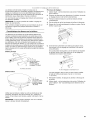
6.
Use adjustable wrench to remove LP hose regulator from
brass elbow. Use adjustable wrench to remove brass elbow
from shutoff valve.
9. Use pipe wrench to install the convertible regulator. Brass
cap will be facing up when tight.
A B
iii _,iiiiiio
A, Brass connector
B. Convertible regulator
10. To set the appliance regulator for LP gas, use adjustable
wrench to remove the brass cap on the convertible regulator.
7.
8.
A. Manifold
B.Brass elbow
C. Rear of grill
D. Gas pressure regulator/hose assembly
Apply pipe sealant to the threads of the brass connector. Use
pipe thread sealant that is certified for use with LP gas.
Use adjustable wrench to install brass connector (supplied) to
shutoff valve.
NOTE: The arrow on the regulator must be pointing toward
the brass connector.
11. Examine the stem on the brass cap. The letters "NAT" should
be showing on the end of the plastic stem farthest away from
the brass cap.
12. Remove stem from cap, turn it over and snap stem back into
the cap so the letters "LP" are at the end of the stem farthest
away from the brass cap.
13. Use adjustable wrench to reinstall cap onto regulator.
Make Grill Connections
Connect Local LP Gas Supply
1. Use pipe wrench to connect certified 1/2"(1.3 cm) gas supply
pipe to inlet side of regulator from Fixed LP gas supply
according to local codes requirements. Use pipe thread
sealant that is certified for use with LP gas at connections
where required. There must be a certified manual shutoff
valve in the gas supply line near the grill for easy access.
2. Turn on the gas supply to the grill.
3. Test all connections by brushing on an approved
noncorrosive leak-detection solution. Bubbles will show a
leak. Correct any leaks found.
Record Conversion
In the last page of the Use and Care Guide, write "Converted to
Local LP Gas Supply." Also record the conversion date and the
technician/company that performed the conversion.
15

Installation of the regulator
1. Turn off the main gas supply valve.
2. Unplug grill or disconnect power.
3. Disconnect 20 Ib LP gas fuel tank (if present).
4. Turn off all burner control valves.
5. Remove rear cover and 2 screws.
6.
Use adjustable wrench to remove LP hose regulator from
brass elbow. Use adjustable wrench to remove brass elbow
from shutoff valve.
9. Use pipe wrench to install the convertible regulator. Brass
cap will be facing up when tight.
A B
iii _'iiiiiio
A. Brass elbow
B. Convertible regulator
10. To make sure the regulator is set for Natural gas, use
adjustable wrench to remove brass cap on appliance
regulator.
7.
8.
A. Manifold
B.Brass elbow
C. Rear of grill
D. Gas pressure regulator/hose assembly
Apply pipe sealant to the threads of the brass connector. Use
pipe thread sealant that is certified for use with LP gas.
Use adjustable wrench to install brass connector (supplied) to
shutoff valve.
NOTE: The arrow on the regulator must be pointing toward
the brass connector.
11. Examine the stem on the brass cap. If the letters "NAT" are
not showing on the end of the plastic stem farthest away from
the brass cap, remove stem from cap, turn it over and snap
stem back into the cap so the letters "NAT" are at the end of
the stem farthest away from the brass cap.
12. Reinstall cap onto convertible regulator.
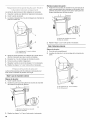
Change the main grill burner valve orifices
1. Manually remove all of the grates, sear plate, and burners.
2. Remove the 2 screws that hold the burner in place. Remove
gas burner from the grill.
A
A. Two screws
16

3= Use 6 mm socket and wrench or 6 mm nut driver to remove
the brass orifices from the end of the gas valves.
A
Change the Rotisserie-infrared burner orifice(s)
1. Remove the access cover and screw at the back of the grill
hood with a Phillips screwdriver.
4=
A. Grill burner orifice
Install new 2.34 mm orifices supplied with this kit to the end
of the gas valve. Use 6 mm socket and wrench or 6 mm nut
driver to tighten.
NOTE: The number 2.34 is stamped on the orifice for
identification.
2=
Use Phillips screwdriver to remove 2 screws holding the
spider guard to the burner.
@
A
B,(
5=
6=
7=
A. Grill burnerorifice
Replace burner by sliding the middle tube (venturi) over the
orifice.
A
B
A.Burner/orifice connection
B.Burner
Reattach gas burner using 2 screws.
)l
A
A. Two screws
Repeat the procedure for each grill burner.
A. Spider guard
B. Two screws
3=
4=
Use 10 mm wrench to remove the brass orifice located at the
end of the supply pipe.
For models with 1 rotisserie burner:
Install 1.9 mm orifice supplied with this kit to the end of the
supply pipe. Use 10 mm wrench to tighten.
For models with 2 rotisserie burners:
Install 1.55 mm orifice supplied with the kit to the end of the
supply pipe. Use 10 mm wrench to tighten.
NOTE: The number 1.9 mm or 1.55 mm is stamped on the
orifice for identification.
5. Replace the spider guard and secure with the 2 screws
removed in Step 2.
6. Repeat the procedure for each rear burner.
Change the Side burner orifices
(for models equipped with side burner)
1. Remove the side burner grates.
2. Remove the burner caps. The caps are interlocked to the
burner base. Twist and lift the burner caps to remove.
3. Use 10 mm socket and wrench or 10 mm nut driver to
remove the brass orifices from inside the burner base.
17

4=
5.
6.
Use 10 mm socket and wrench or 10 mm nut driver to install
the new 2.1 mm orifices supplied with this kit.
NOTE: The number 2.1 is stamped on the orifice for
identification.
Repeat the procedure for the other burner.
Replace the burner top and caps. Align the notches in the
bottom of the burner top with the tabs on the burner base
and twist until the burner top is seated on the burner base.
You will feel it drop into the deep notch.
A B
A.Burner top notches
B. Burnerbase tabs
7. Replace the side burner grates.
Change the Sear burner orifices
(for models equipped with sear burner)
1. Remove the sear burner cover screws. Set the screws and
cover aside.
2.
3.
A. Sear burner cover screws
Remove the burner igniter mounting screws.
Loosen the sear burner plate, located next to the igniter.
A
A. Burner igniter mounting screws
4. Remove the sear burner mounting screws.
A
5=
6.
A. Sear burner mounting screws
Lift the sear burner out of the grill.
Use 6 mm socket wrench or 6 mm nut driver to remove the
orifice. Install the new 2.34 mm orifice supplied.
NOTE: The number 2.34 is stamped on the orifice for
identification.
7. Reinstall sear burner. Make sure that the igniter is out of the
way to allow proper positioning of burner. Use Phillips
screwdriver to attach the mounting screws.
8. Use Phillips screwdriver to reattach the igniter and sear
burner plate.
9. Reinstall sear burner cover. Use Phillips screwdriver to attach
mounting screws.
Hook up to Natural gas and Leak Test
1. Use pipe wrench to connect certified 1/2"(1.3 cm) gas supply
pipe to inlet side of regulator from Natural gas supply
according to local codes requirements. Use pipe thread
sealant that is certified for use with LP gas at connections
where required. There must be a certified manual shutoff
valve in the gas supply line near the grill for easy access.
2. Turn on the gas supply to the grill.
3. Test all connections using an approved noncorrosive leak-
detection solution. Bubbles will show a leak. Correct any leak
found.
Record Conversion
1. The appliance nameplate is located inside the grill cabinet on
the right-hand cabinet side. With a permanent marker, check
the box next to "Natural gas" and mark through "LP -
Propane."
In the last page of the Use and Care Guide, write "Converted to
Natural Gas." Also record the conversion date and the
technician/company that performed the conversion.
NOTE: Place LP gas parts in plastic parts bag for future use and
keep with pack containing literature.
18

The burners are tested and factory-set for most efficient 5.
operation. However, variations in gas supply and other conditions
may make minor adjustments to air shutter or low flame setting
necessary.
It is recommended that a qualified person make burner
adjustments.
NOTE: The rotisserie burner cannot be adjusted.
Checking and adjusting the grill burner flames requires removing
the grate and sear plates.
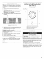
Burner Flame Characteristics
The flames of the grill burners and side burners (on some models)
should be blue and stable with no excessive noise or lifting (LP
gas flames will have a slightly yellow tip). A yellow flame indicates
not enough air. If flame is noisy or lifts away from the burner, there
is too much air. Some yellow tips on flames when the burner is
set to HI setting are acceptable as long as no carbon or soot
deposits appear.
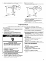
Main burner
Remove the 2 screws that hold the burner in place. Remove
gas burner from the grill.
6.
A
A.2 screws
If flame is yellow (not enough air), turn air shutter adjustment
screw counterclockwise.
If flame is noisy or lifts away from burner (too much air), turn
air shutter adjustment screw clockwise.
Side burner
A
A. Burner ports
1"
(1.9 - 2.5 crn)
on all burner ports
with burners on
"Hi" setting
(1.9-2.5cm)
on aH burner ports
with burners on
setting
Check that burners are not blocked by dirt, debris, insect nests,
etc. and clean as necessary. If they are clean, adjust air shutters
as needed.
IMPORTANT: Before adjusting air shutters, let burners cool
completely.
To Adjust:
1. Light grill using information in the "Outdoor Grill Use" section.
2. Observe flame to determine which burners need adjustment
and how the flame is acting.
3. Turn off the valve and wait until grill and burners cool
completely.
4. Remove grill grates and sear plates.
A
A.Air shutteradjustment screw
7.
8.
Adjustment should be made clockwise or counterclockwise
from V8"(3.2 mm) to V4"(6.4 mm).
Replace gas burner, sear plates and grates.
Light grill using information inthe "Outdoor Grill Use" section.
See "Burner Flame Characteristics."
Low Flame Adjustment
If flame goes out on the "LO" setting, the low flame setting must
be adjusted.
1. Turn off the valve and wait until grill and burners are cool.
2. Remove grill grates and sear plates.
3. Light grill using information in the "Outdoor Grill Use" section.
4. Turn burner to its lowest setting and remove knob.
5. Hold valve stem with pliers and insert a small flat-blade
screwdriver into the shaft.
6. Watch the flame and slowly turn the screwdriver
counterclockwise.
7. Adjust flame to minimum stable flame.
C
A. Valve stem
B. Small flat-blade screwdriver
C. Pliers
8. Replace the control knob and turn off the burner.
9. Repeat steps 3 through 8 for each burner if needed.
10. Replace the sear plates and grates after the burners have
cooled.
19

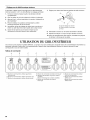
OUTDOOR GRILL USE
This manual covers several different models. The grill you have purchased may have some or all of the features listed. The locations and
appearances of the features shown here may not match those of your model.
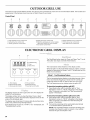
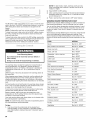
Control Panel
A B C D E F G H /
ROTISSERIE LEFT CENTER RIGHT SEAR ROTISSERIE FRONT REAR
BURNER BURNER BURNER BURNER BURNER BURNER BURNER BURNER
A. Left rotisserie burner control knob
B. Left grill burner control knob
C. Center grifl burner control knob
D. Right grill burner control knob
E. Electronic grill display (on some models)
Light switch button (on some models)
F Sear burner control knob
G. Right rotisserie burner control knob
H. Front side burner control knob
I. Rear side burner control knob
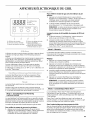
ELECTRONIC GRILL DISPLAY
A B
O Fuel Remaining
O Timer
O Flame Time
C
Time Set Start/Reset
© ©
D E F
A. Timer display
B. Mode indicator fights
C. Mode selection button
D. Time set button
E. Start/reset button
F Hood light on/off button
The display will turn on when a gas burner is lit. The display will
default to Fuel Remaining.
This display will also turn on when the Mode, Timer or Start/
Reset button is pushed. The information displayed will be for the
mode of the lit indicator light.
The display area will go blank 10 minutes after the last time that a
button was pushed (except the light button).
If the display does not turn on or if "NP" or "El" is displayed, see
"Troubleshooting" section.
The Start/Reset button starts the Timer and Flame Time TM cycle.
This button also stops and resets these features.
The mode button selects features on the display control.
When the grill is not lit and the Mode button is pushed, it will only
display the information for Modes 1 and 2. The grill must be lit for
Mode 3 to be activated.
Mode I - Fuel Remaining Feature
The fuel remaining feature displays a calculated amount of time
(hours and minutes) the grill can remain lit at the current gas
usage rate before the 201b LP gas fuel tank runs out of fuel.
The Fuel Remaining can be checked when the grill is OFE
To
1.
check fuel remaining with the grill OFF:
Press Mode button until the indicator light for "Fuel
Remaining" comes on. "00:00" will appear in the display.
After 10 seconds a calculated Fuel Time Remaining will
appear in the display.
To check fuel remaining with the grill burners ON:
1. Press Mode button until the indicator light for "Fuel
Remaining" comes on. "00:00" will appear in the display.
After 10 seconds a calculated Fuel Time Remaining will
appear in the display.
2. The fuel time remaining will be recalculated automatically
7-10 minutes after the grill has been lit.
NOTE: This recalculated display of fuel time remaining may
increase when the grill is used on medium or low settings
because the gas consumption is less.
20
La page charge ...
La page charge ...
La page charge ...
La page charge ...
La page charge ...
La page charge ...
La page charge ...
La page charge ...
La page charge ...
La page charge ...
La page charge ...
La page charge ...
La page charge ...
La page charge ...
La page charge ...
La page charge ...
La page charge ...
La page charge ...
La page charge ...
La page charge ...
La page charge ...
La page charge ...
La page charge ...
La page charge ...
La page charge ...
La page charge ...
La page charge ...
La page charge ...
La page charge ...
La page charge ...
La page charge ...
La page charge ...
La page charge ...
La page charge ...
La page charge ...
La page charge ...
La page charge ...
La page charge ...
La page charge ...
La page charge ...
La page charge ...
La page charge ...
La page charge ...
La page charge ...
La page charge ...
La page charge ...
La page charge ...
La page charge ...
La page charge ...
La page charge ...
La page charge ...
La page charge ...
La page charge ...
La page charge ...
La page charge ...
La page charge ...
La page charge ...
La page charge ...
La page charge ...
La page charge ...
-
 1
1
-
 2
2
-
 3
3
-
 4
4
-
 5
5
-
 6
6
-
 7
7
-
 8
8
-
 9
9
-
 10
10
-
 11
11
-
 12
12
-
 13
13
-
 14
14
-
 15
15
-
 16
16
-
 17
17
-
 18
18
-
 19
19
-
 20
20
-
 21
21
-
 22
22
-
 23
23
-
 24
24
-
 25
25
-
 26
26
-
 27
27
-
 28
28
-
 29
29
-
 30
30
-
 31
31
-
 32
32
-
 33
33
-
 34
34
-
 35
35
-
 36
36
-
 37
37
-
 38
38
-
 39
39
-
 40
40
-
 41
41
-
 42
42
-
 43
43
-
 44
44
-
 45
45
-
 46
46
-
 47
47
-
 48
48
-
 49
49
-
 50
50
-
 51
51
-
 52
52
-
 53
53
-
 54
54
-
 55
55
-
 56
56
-
 57
57
-
 58
58
-
 59
59
-
 60
60
-
 61
61
-
 62
62
-
 63
63
-
 64
64
-
 65
65
-
 66
66
-
 67
67
-
 68
68
-
 69
69
-
 70
70
-
 71
71
-
 72
72
-
 73
73
-
 74
74
-
 75
75
-
 76
76
-
 77
77
-
 78
78
-
 79
79
-
 80
80


KitchenAid KFRU271VSS00 Guide d'installation
- Catégorie
- Barbecues
- Taper
- Guide d'installation
- Ce manuel convient également à
dans d''autres langues
Documents connexes
-
KitchenAid KFRS365TSS00 Le manuel du propriétaire
-
KitchenAid KFRS361TSS Manuel utilisateur
-
-
-
-
KitchenAid KFRU488TSS00 Le manuel du propriétaire
-
KitchenAid KBNU367VSS00 Le manuel du propriétaire
-
-
-