Edge-Core Edge-core OAP100e 802.11ac Wave 2 Dual-Band Enterprise Access Point Mode d'emploi
- Catégorie
- Les routeurs
- Taper
- Mode d'emploi
Ce manuel convient également à

– 1 –
Quick Start Guide
802.11ac Wave 2 Dual-Band Enterprise Access Point
OAP100e
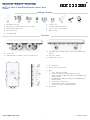
Package Contents
Overview
1.
OAP100e access point
2. Mounting kit—2 brackets and 2 steel hose clamps
3. (Optional) Mounting bracket
4. DC Terminal plug
5. 2 x Cable glands
6. 2 x Port covers
7. 2 x External 5G omni antennas
8. Console cable—RJ-45 to DB-9
9. QR code card
1
4 5 6 8 9
2
4
3
23
1.
Mounting points
2. Enclosure for optional module
3. LEDs:
■Power: On red (power OK)
■System: On green (power OK), Blinking (boot up)
■Uplink: On amber (1Gbps link), On green (10/100Mps link),
Blinking (traffic)
■LAN: On amber (1Gbps link), On green (10/100Mps link),
Blinking (traffic)
■LTE: function not supported
■2.4G: On blue (radio on), Blinking (traffic)
■5G: On blue (radio on), Blinking (traffic)
4. Reset button
1
1
1
1
1
1
1.
Grounding point
2. Console port
3. LAN (PoE Out) port: 1Gbps connection to LAN devices
4. Uplink (PoE In) port: 1Gbps uplink connection with 802.3at PoE
support
5. DC In port: 24 Vdc
6. 5G Antenna connector
234 5
1
66
E042022-MR-R01
www.edge-core.com
7
3

Quick Start Guide
– 2 –
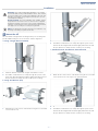
Mount the AP
The included mounting brackets are designed for pole mounting and
provide additional degrees of movement for antenna alignment.
a. Using a Single Bracket (Parallel)
1. Install the bracket onto the AP using the included four screws.
2. Thread the included steel hose clamps through the eyelets on the
back of the Mounting Bracket and then lightly fasten them around
the pole. Both hose clamps must be used for pole mounting.
b. Using Two Brackets (Tilt)
1. Attach the two main sections of the bracket using the four included
screws and lock nuts.
.
2. Install the bracket onto the AP using the included four screws.
3. Thread the included steel hose clamps through the eyelets on the
back of the Mounting Bracket and then lightly fasten them around
the pole. Both hose clamps must be used for pole mounting.
c. (Optional) Using Two Brackets (Perpendicular)
1. Attach the two main sections of the bracket using the four included
screws and lock nuts. This requires an optional bracket.
2. Install the bracket onto the AP using the included four screws.
3. Thread the included steel hose clamps through the eyelets on the
back of the Mounting Bracket and then lightly fasten them around
the pole. Both hose clamps must be used for pole mounting.
Warning:
For a safe and reliable installation, use only the
accessories and screws provided with the device. Use of other
accessories and screws could result in damage to the unit. Any
damages incurred by using unapproved accessories are not
covered by the warranty.
Avertissement:
Pour une installation sûre et fiable, utilisez
uniquement les accessoires et les vis fournies avec l’appareil.
L’utilisation d’autres accessoires et vis pourrait endommager
l’appareil. Les dommages causés par l’utilisation d’accessoires
non approuvés ne sont pas couverts par la garantie.
Note:
The drawings in this document are for illustration only
and may not match your particular model.
1
2
1
3
2
Installation

Quick Start Guide
– 3 –
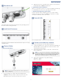
Ground the AP
Ground the AP by connecting a ground wire to the grounding point on
the device and to nearby good earth.
Install the 5G Antennas
Install approved cellular 5G omni external antennas to improve coverage
and performance.
Connect Cables
a. Connect LAN Cables
1.
Connect Category 5e or better cable to the Uplink (PoE In)
1000BASE-T
RJ-45 port. When connected to a PoE source, the
Uplink (PoE In) port connection provides power to the unit.
2. (Optional) Connect a local LAN switch, computer or other device to
the LAN (PoE Out) 1000BASE-T RJ-45 port.
b. (Optional) Connect DC Power
When not connected to a PoE source, wire the included DC terminal plug
to a 10–24 VDC, 0.5-1 A source to provide power to the AP.
c. (Optional) Management Connections
Connect an RJ-45 to DE-9 straight-through console cable and then
configure the serial connection: 115200 bps, 8 characters, no parity,
one stop bit, 8 data bits, and no flow control.
Check AP LEDs
Power and System LEDs—on green for normal operation.
Connect to the Web User Interface
1.
Connect a PC directly to the AP’s LAN (PoE Out) port.
2. Set the PC IP address to be on the same subnet as the AP LAN port
default IP address. (The PC address must start 192.168.1.x with
subnet mask 255.255.255.0.)
3. Enter the AP’s default IP address of 192.168.1.10 into the web
browser address bar.
4. Log in to the web interface using default settings:
Username = admin
Password = admin
Note:
Port covers and cable glands should be tightned to a
torque of 10 kgf.cm.
2
3
3
Note:
To connect to the web interface using the Uplink (PoE
In) port, the IP address is automatically assigned through DHCP
by default. If a DHCP server is unreachable, the Uplink(PoE)
port reverts to a fallback IP address of 192.168.1.10.
4
5

Quick Start Guide
– 4 –
Safety and Regulatory Information
FCC Class B
This equipment has been tested and found to comply with
the limits for a
Class B digital device, pursuant to Part
15 of the FCC Rules. These limits
are designed to provide reasonable protection against harmful
interference in a residential installation. This equipment generates, uses
and can radiate radio frequency energy and, if not installed and used in
accordance with the instructions, may cause harmful interference to radio
communications. However, there is no
guarantee that interference will
not occur in a particular installation. If this equipment does cause
harmful interference to radio or television reception, which can be
determined by turning the equipment off and on, the user is encouraged
to try to correct the interference
by one of the following measures:
■
Reorient or relocate
the receiving antenna
■
Increase the separation between the equipment and receiver
■
Connect the equipment into an outlet on a circuit different from
that to which the receiver is connected
■
Consult the dealer or an experienced radio/TV technician for
help
FCC Caution:
Any changes or modifications not expressly approved by
the party responsible for compliance could void the user’s authority to
operate this equipment.
This device complies with Part 15 of
the FCC Rules. Operation is subject
to the following two conditions: (1) This device may not cause harmful
interference, and (2) this device must
accept any interference received,
including interference that may cause undesired operation.
For product available in the USA/Canada market, only channel
1~11 can be operated. Selection of other channels is not possible.
IMPORTANT NOTE:
FCC Radiation Exposure Statement:
This equipment complies with FCC radiation exposure limits set forth for
an uncontrolled environment. This
equipment should be installed and
operated with minimum distance 46 cm between the radiator and your
body.
Professional Installation Instructions
1. Installation personnel
This product is designed for specific
applications and should be installed
by qualified personnel who have
knowledge of RF and its related
regulations. A general user shall not attempt to install or modify the
equipment configuration.
2. Installation location
To meet regulatory RF exposure requirements, this product shall be
installed at a location where, during normal operations, the radiating
antenna is at least 45 cm away from any nearby persons.
3. External antenna
Use only the antennas which have
been approved by the applicant.
Using non-approved antenna(s) is prohibited and may produce
unwanted spurious or excessive RF transmitting power which may lead to
a violation of FCC limits.
4. Installation procedure
Please refer to this equipment's user manual for the procedure details.
5. Warning
The installation position must be carefully selected so that the final output
power does not exceed the
limit set forth in relevant
regulations. Violation
of output power regulations could
lead to serious federal penalties.
Industry Canada
This device contains licence-exempt transmitter(s)/receiver(s) that comply
with Innovation, Science and Economic Development Canada’s licence-
exempt RSS(s). Operation is subject to the following two conditions:
(1) This device may not cause interference.
(2) This device must accept any interference, including interference that
may cause undesired operation of the device.
Cet appareil contient des émetteurs /
récepteurs exempts de licence qui
sont conformes au (x) RSS (s) exemptés
de licence d’Innovation, Sciences
et Développement économique Canada. L’opération est soumise aux
deux conditions suivantes:
(1) Cet appareil ne doit pas
provoquer d’interférences.
(2) Cet appareil doit accepter toute interférence, y compris les
interférences susceptibles de provoquer un fonctionnement indésirable de
l’appareil.
The device for operation in the band 5150–5250 MHz is only for indoor
use to reduce the potential for harmful interference to co-channel mobile
satellite systems.
Les dispositifs fonctionnant dans la bande 5150-5250 MHz sont réservés
uniquement pour une utilisation à l’intérieur afin de réduire les risques de
brouillage préjudiciable aux systèmes
de satellites mobiles utilisant les
mêmes canaux.
CE Statement
This equipment complies with EU radiation exposure limits set forth for an
uncontrolled environment. This
equipment should be installed and
operated with minimum distance 20 cm between the radiator and your
body.
The device is restricted to indoor
use only when operating in the
5150 to 5350 MHz frequency range.
All operational modes:
2.4 GHz: 802.11b, 802.11g, 802.11n (HT20), 802.11n (HT40),
802.11ac (VHT20), 802.11ac (VHT40), 802.11ax (HE20),
802.11ax (HE40)
5 GHz: 802.11a, 802.11n (HT20), 802.11n (HT40), 802.11ac
(VHT20), 802.11ac (VHT40), 802.11ac (VHT80), 802.11ax (HE20),
802.11ax (HE40), 802.11ax (HE80)
BLE 2.4 GHz: 802.15.1
The frequency and maximum transmitted power limit in EU are listed
as below:
2412-2472 MHz: 20 dBm
5150-5350 MHz: 23 dBm
5500-5700 MHz: 30 dBm
The abbreviations of the countries, as prescribed in above table, where
any restrictions on putting into service or any requirements for
authorization of use exist.
CZCYCHBGBEAT
FIESELEEDKDE
ITISIEHUHRFR
NLMTLVLULTLI
SISEROPTPLNO
UKTRSK

Quick Start Guide
– 5 –
CE Mark Declaration of Conformance for EMI and Safety (EEC)
This information technology equipment is in compliance with the
Directive 2014/53/EU and Directive 2014/35/EU.
The Declaration of Conformity (DoC) can be obtained from
www.edge-core.com -> support -> download.
Warnings and Cautionary Messages
Hardware Specifications
Warning:
This product does not contain any serviceable user
parts.
Warning:
Installation and removal of the unit must be carried
out by qualified personnel only.
Caution:
Wear an anti-static wrist strap or take other suitable
measures to prevent electrostatic discharge when handling this
equipment.
Caution:
Do not plug a phone jack connector in the RJ-45
port. This may damage this device.
Caution:
Use only twisted-pair cables with RJ-45 connectors
that conform to FCC standards.
AP Chassis
Size (WxDxH) 230 x 450 x 65 mm (9.06 x 17.72 x 2.56 in.)
Weight X.XX kg (X.XXX lb)
Temperature Operating: -40° C to 65° C (-40° F to 149° F)
Storage: -40° C to 70° C (-40° F to 158° F)
Humidity Operating: 5% to 95% (non-condensing)
Network Interfaces
Ports Uplink (PoE In) RJ-45 Port: 1000BASE-T, PoE PD
LAN (PoE Out) RJ-45 Port: 1000BASE-T, PoE PSE
2.4 GHz Radio IEEE 802.11b/g/n
5 GHz Radio IEEE 802.11a/ac/n
Bluetooth BLE/BT4.1
Radio Frequencies 2.4–2.4835 GHz (US and ETSI)
US
5.15–5.25 GHz (lower band)
5.725–5.825 GHz (upper band)
Europe
5.15–5.25 GHz, 5.25–5.35, 5.47–5.725 GHz
Power Specifications
PoE Input Power 22.4 W max
802.3at-compliant
DC Power 24 VDC, 1.09 A
Regulatory Compliances
Radio EN 300 328 V2.2.2 (2.4G/BT-LE)
EN 301 893 V2.1.1 (5G)
EN 303 413 V1.1.1 (GPS)
EN 50385 / EN 62311: 2017 (MPE)
Emissions EN 301 489-1 V2.1.1
EN 301 489-17 V3.1.1
EN 301 489-52 V1.1.0
Safety EN 62368-1: 2014 + A11: 2017
EN 60950-22: 2017
IEC 62368-1: 2014 (Second Edition)
IEC 60529: 1989+AMD1: 1999+ AMD2:
2013CSV (IP55)
Warranty Information and Technical Support
Registering your product enables you to receive a more efficient warranty service. Be sure to register at www.edge-core.com.
-
 1
1
-
 2
2
-
 3
3
-
 4
4
-
 5
5


Edge-Core Edge-core OAP100e 802.11ac Wave 2 Dual-Band Enterprise Access Point Mode d'emploi
- Catégorie
- Les routeurs
- Taper
- Mode d'emploi
- Ce manuel convient également à
dans d''autres langues
Documents connexes
Autres documents
-
Asus ZenWiFi CT8 Manuel utilisateur
-
Cisco C9117AXI-x Getting Started Manual
-
Aruba 630 series Guide d'installation
-
-
Watchguard AP327X Hardware Guide
-
Dell W-Series 304/305 Access Points Guide de démarrage rapide
-
Dell W-Series 314/315 Access Points Le manuel du propriétaire
-
Alcatel-Lucent OAW-AP Guide d'installation
-
Aruba AP-515 Guide d'installation
-
Mediatek MT7922A22M Mode d'emploi