
T.Flow® Hygro+
T.Flow® Nano
Abrégé de montage FR
Abridged installation instructions EN
Montage-Kurzfassung DE
Resumen de montaje ES

2
560 mm
1197 mm
582 mm
566 mm
500 mm
444 mm
600 mm mini.
si cloisons amovibles pour maintenance
600 mm mini
.
444 mm
600 mm mini.
si cloisons amovibles pour maintenance
600 mm mini.
1197 mm
350
MINI
Kg
350
MINI
Kg
350
MINI
Kg
350
MINI
Kg
350
MINI
Kg
350
MINI
Kg
Ce guide ne se substitue pas à la notice complète d’installation. Pour plus d’informations,
veuillez vous référer à la notice complète d’installation.
Toute défaillance de l’installation liée à un non respect des préconisations du fabricant, au non respect des normes
et réglementations en vigueur, ou à un manque d’entretien donnera lieu à une exclusion de garantie.
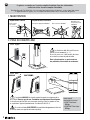
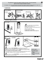
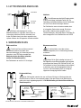
1. MANUTENTION
Déplacements incorrects
Manutention par
une personne seule
INTERDITE
Prise par les piquages INTERDITE Ecran vers le bas INTERDIT
30° max
Écran toujours
vers le haut
Déplacement correct
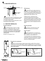
2. POSE DU CHAUFFE-EAU
350
MINI
Kg
350
MINI
Kg
350
MINI
Kg
600 mm mini.
avec cloisons amovibles pour maintenance
600 mm mini
.
600 mm mini.
avec cloisons amovibles pour maintenance
600 mm mini.
560 mm
1197 mm
582 mm
566 mm
500 mm
444 mm
600 mm mini.
avec cloisons amovibles pour maintenance
600 mm mini.
573 mm
566 mm
582 mm
T.Flow
®
Hygro+
T.Flow
®
Nano
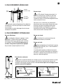
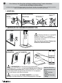
Le chauffe-eau doit être installé sur une
surface lisse et horizontale (+/- 1°).
Si ce n’est pas le cas, il doit être mis de niveau
en le calant au niveau du pied du ballon.
Sans cette précaution, on peut rencontrer
des problèmes d’évacuation de condensats.
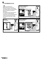
L’installation MURALE du chauffe-eau doit respecter les exigences de la
NF DTU 60.1.Selon le type de mur, l’installation sur trépied peut-être obligatoire.
Le chauffe eau doit être fixé au mur avec des chevilles et des vis adaptés au mur
et au poids de l’appareil (conformément à la Norme EN 60-335-1).
En cas d’installation SUR TRÉPIED, le produit doit obligatoirement être fixé
au mur (au moins sur support de fixation supérieur).
MURALE SUR TRÉPIED
Poids indicatif
du chauffe-eau en eau
• B100 T.Flow Nano :
176 kg
• B100 FAN-T.Flow Nano :
178 kg
FR

3
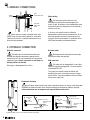
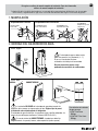
Les gaines doivent obligatoirement être solidarisées
au chauffe-eau, en utilisant par exemple les colliers fournis
en accessoires.
Veillez toutefois à ce qu’un démontage futur des réseaux
aérauliques reste possible.
La PAC prélevant l’énergie contenue dans l’air
extrait, l’air vicié rejeté par le système est froid. Pour
éviter tout risque de condensation, à l’intérieur ou à
l’extérieur de la gaine, le réseau doit obligatoirement être
isolé au minimum à 25 mm.
Dans tous les cas, la sortie d’air sera suffisamment
dimensionnée pour ne pas générer d’importantes pertes
de charge. Une sortie d’air générant trop de pertes
de charge aérauliques peut engendrer un mauvais
fonctionnement du système. Utiliser de préférence les
sorties toitures/murales aérauliques ALDES.
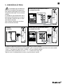
3. RACCORDEMENT AÉRAULIQUE
4. RACCORDEMENT HYDRAULIQUE
Aspiration
(air extrait chaud)
Face avant
avec panneau
de contrôle
Rejet
(air froid)
Il est obligatoire d’équiper les piquages “arrivée
d’eau froide” et “départ d’eau chaude” de raccords
diélectriques (fournis avec l’appareil) même si le ballon
est raccordé en tube PER. En cas d’absence de ces
raccords, notre garantie ne pourrait être appliquée.
L’installation d’un ou plusieurs limiteurs de
température (non fournis) est conseillée.
Prévoir un siphon d’écoulement et le charger en eau (il est aussi possible d’utiliser un siphon
à membrane qui ne nécessite pas de charge en eau). Vérifiez le cheminement du tube une fois
raccordé afin d’éviter tout pincement de celui-ci. En cas de non respect de ces consignes, notre
garantie ne pourrait être appliquée.
Équipez obligatoirement l’installation d’un groupe
de sécurité neuf (non fourni), taré à 7 bars et conforme à
la norme NF EN 1487.
L’installation doit comporter un réducteur de pression
(non fourni) si la pression d’alimentation est supérieure à
0,45 MPa. Le réducteur de pression doit être installé au
départ de la distribution générale.
Ne pas exercer un couple supérieur à 25 N.m.
Raccords diélectriques Piquage eau chaude
Évacuation des condensats
Piquage eau froide
Tube condensat : à raccorder au siphon d’écoulement des eaux usées.
Siphon
Arrivée d’eau
générale
Groupe de sécurité Tube de condensat
Raccord membrane
Schéma 2
Évacuation eaux
usées (égouts)
Siphon
Arrivée d’eau
générale
Tube de condensat
Raccord membrane
Schéma 1
Groupe de sécurité
Évacuation eaux
usées (égouts)
Siphon
Arrivée d’eau
générale
Groupe de sécurité Tube de condensat
Raccord membrane
Schéma 2
Évacuation eaux
usées (égouts)
Siphon
Arrivée d’eau
générale
Tube de condensat
Raccord membrane
Schéma 1
Groupe de sécurité
Évacuation eaux
usées (égouts)
Réseau de rejet
FR

4
Chauffe eau
Alim
sous
DDR
30mA
contacteur heures
creuses
Compteur EDF
Branchement double tarif 1,
avec contacteur Heures Creuses
LN45
Contact EDF Tableau électrique
Alim. jour/nuit
2x1,5mm2
2 x 1,5mm2
2A
N
N
16A
N
N
A1 A2
Contact EDF Tableau électrique
Alim
sous
DDR
30mA
2 x 1,5mm2
Compteur EDF
Alim. jour/nuit
2x1,5mm2
Branchement double tarif 2,
sans contacteur Heures Creuses
Chauffe eau
LN45
2A
N
N
16A
N
N
Alim
sous
DDR
30mA
Chauffe eau
Branchement
en simple tarif
Tableau électrique
LN45
16A
N
N
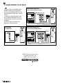
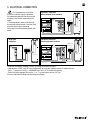
5. BRANCHEMENT ÉLECTRIQUE
Le chauffe-eau thermodynamique
doit être alimenté de façon permanente
pour assurer la production d’ECS et le bon
fonctionnement de l’anode Titane à courant
imposé.
Le chauffe-eau thermodynamique ne doit
être raccordé électriquement qu’une fois
le remplissage en eau réalisé et les gaines
raccordées.
Ne jamais alimenter électriquement et
directement l’élément chauffant.
ALDES Service Consommateur
20 boulevard Joliot Curie
69694 Vénissieux Cedex
Branchement double tarif 1,
sans contacteur Heures Creuses
Branchement double tarif 2,
avec contacteur Heures Creuses
Branchement
en simple tarif
FR

560 mm
1197 mm
582 mm
566 mm
500 mm
444 mm
Min. 600 mm
if partition walls can be moved for maintenance
Min. 600 mm
444 mm
Min. 600 mm
if partition walls can be moved for maintenance
Min. 600 mm
1197 mm
Kg
Kg
MIN.
Kg
350
MIN.
350
MIN.
350
Kg
Kg
MIN.
Kg
350
MIN.
350
MIN.
350
5
This guide does not replace the complete installation instructions. For further information,
please refer to the complete installation instructions.
Any equipment failure due to non-observance of manufacturer instructions and failure to respect applicable standards and
regulations or lack of maintenance shall render the warranty null and void.
1. HANDLING
Incorrect handling
MUST NOT be
handled by one
person alone
NEVER handle using
the connection holes NEVER handle with
the screen face down
30° max
Screen must
face upwards
Correct handling
2. HEATER INSTALLATION
Kg
Kg
MIN.
Kg
350
MIN.
350
MIN.
350
Min. 600 mm
if partition walls can be moved for maintenance
Min. 600 mm
Min. 600 mm
if partition walls can be moved for maintenance
Min. 600 mm
560 mm
1,197 mm
582 mm
566 mm
500 mm
444 mm
Min. 600 mm
if partition walls can be moved for maintenance
Min. 600 mm
573 mm
566 mm
582 mm
T.Flow
®
Hygro+
T.Flow
®
Nano
The water heater must be installed on a
smooth, horizontal surface (+/- 1°).
If the surface is not level, the water heater must be
made level using its legs.
If this precaution is not taken,
condensation evacuation issues may occur.
If the heater is WALL-MOUNTED the installation must respect the
requirements of French standard NF DTU 60.1. Depending on the type of wall, it
may be necessary to install the heater on a tripod.
The water heater must be attached to the wall using screws and wall plugs suited to
the wall and the weight of the unit (in accordance with EN 60-335-1).
If the heater is installed ON A TRIPOD, it must always be fixed to the wall (at
least by the upper attachment bracket).
WALL
MOUNTED
ON FRAME
Indicative weight
of filled water heater
• B100 T.Flow Nano:
176 kg
• B100 FAN-T.Flow Nano:
178 kg
EN

6
Ducts must be securely connected to the water
heater, using the clamp collars supplied as accessories.
However, ensure that it is possible to disconnect the air
ducts for future purposes.
The heat pump captures the heat in the
extracted air so the exhaust air discharged by the
system is cold. To avoid any risk of condensation inside
or outside the duct, the ducting must be insulated to a
minimum of 25 mm.
In all events, the air outlet must be sufficiently
dimensioned to avoid extensive pressure losses. An air
outlet that generates excessive pressure losses may
cause the system to malfunction. It is preferable to use
ALDES roof-mounted or wall-mounted outlets.
3. AERAULIC CONNECTIONS
4. HYDRAULIC CONNECTION
Inlet
(extracted hot air)
Front side
with control
panel
Outlet
(cold air)
The cold water inlet and hot water outlet must
be fitted with dielectric connectors (supplied with the
heater unit) even if the tank connections use cross-linked
polyethylene pipe. If these connectors are not fitted, our
warranty will be null and void.
We recommend the installation of one or more
temperature limiters (not supplied).
Install a drain siphon and fill it with water (a membrane siphon can also be used, which does
not need to be filled with water). Check the pipe routing once connected to avoid any pinching.
If these instructions are not respected, our warranty will be null and void.
The heater must be equipped with a new safety
switch (not supplied) configured to 7 bar and compliant
with standard EN 1487.
The system must include a pressure reducer (not
supplied) if the mains water supply pressure is higher
than 0.45 MPa. The pressure reducer must be installed
on the mains supply inlet.
Never apply a torque greater than 25 N.m.
Dielectric connectors Hot water outlet
Condensate discharge
Cold water inlet
Condensate tube: must be connected to the waste water siphon.
Water trap
Mains water
inlet
Safety switch Condensate pipe
Membrane connection
Diagram 2
Wastewater outlet
(drains)
Water trap
Mains water
inlet
Condensate pipe
Membrane connection
Diagram 1
Safety switch
Wastewater outlet
(drains)
Water trap
Mains water
inlet
Safety switch
Condensate pipe
Membrane connection
Diagram 2
Wastewater outlet
(drains)
Water trap
Mains water
inlet
Condensate pipe
Membrane connection
Diagram 1
Safety switch
Wastewater outlet
(drains)
Outlet ducting
EN

Water heater
off-peak hours
contact
Electric meter
Dual tariff 1 connection
with off-peak hours contact
LN45
Electric contact Distribution panel
Day/night power
2x1.5 mm²
2x1.5 mm²
2A
N
N
16A
N
N
A1 A2
Power
protected
by RCD
30mA
Electric contact Distribution panel
Power
protected
by RCD
30mA
2x1.5 mm²
Electric meter
Day/night power
2x1.5 mm²
Dual tariff 2 connection without
off-peak hours contact
Water heater
LN45
2A
N
N
16A
N
N
Water heater
Single tarif
f
connection
Distribution panel
LN45
16A
N
N
Power
protected
by RCD
30mA
7
5. ELECTRICAL CONNECTION
• The thermodynamic water heater
must have a constant supply to guarantee
the production of domestic hot water and the
operation of the titanium impressed current
anode.
• The thermodynamic water heater must not
be electrically connected until it has been filled
with water and the pipes connected.
Never supply the heating element directly with
power.
By default, the interface language is French. To change the interface to English:
- Hold down the “MODE” and “OK” keys simultaneously for a very brief moment to enter the advanced menu;
- Press “+” to show the “LANG. <> LANGUAGE menu ”and“ OK ”to validate the selection;
- Select the English language (En) with the “+” or “-” key and confirm with the “OK” key.
All menus and interface settings are now displayed in English.
Dual tariff 1 connection
without off-peak hours contactor
Dual tariff 2 connection
with off-peak hours contactor
Single tariff
connection
EN

8
Diese Anleitung ist kein Ersatz für die vollständige Installationsanleitung. Für weitere Informationen,
lesen Sie bitte die vollständige Installationsanleitung.
Installationsfehler, die auf die Nichtbeachtung der Vorschriften des Herstellers, der geltenden Normen und Rechtsvorschriften
oder auf mangelnde Wartung zurückzuführen sind, führen zum Verlust der Garantie.
560 mm
1197 mm
582 mm
566 mm
500 mm
444 mm
600 mm mini.
falls Wände für Wartungsarbeiten entfernt werden können
600 mm mini
.
444 mm
600 mm mini.
si cloisons amovibles pour maintenance
600 mm mini.
1197 mm
350
MINI
Kg
350
MINI
Kg
350
MINI
Kg
350
MINI
Kg
350
MINI
Kg
350
MINI
Kg
1. WARTUNG
Falsche Beförderung
Gerät nicht alleine
handhaben
Gerät nicht an den
Anschlüssen tragen Das Display darf nicht
nach unten zeigen
30° max
Bildschirm muss
stets nach
oben zeigen
Korrekte Beförderung
2. ANBRINGEN DES WARMWASSERBEREITERS
350
MINI
Kg
350
MINI
Kg
350
MINI
Kg
600 mm mini.
mit abnehmbaren Trennwänden zur Wartung
600 mm mini
.
600 mm mini.
avec cloisons amovibles pour maintenance
600 mm mini.
560 mm
1197 mm
582 mm
566 mm
500 mm
444 mm
600 mm mini.
avec cloisons amovibles pour maintenance
600 mm mini.
573 mm
566 mm
582mm
T.Flow
®
Hygro+
T.Flow
®
Nano
Der Warmwasserbereiter ist auf einer glatten
und ebenen Oberfläche (+/- 1°) aufzustellen.
Ansonsten ist er durch Verkeilen der Speicherfüße
entsprechend auszurichten.
Ohne diese Vorkehrung könnten Probleme beim
Abführen des Kondensats auftreten.
Die WANDMONTAGE des Wasserbereiters hat entsprechend den
Anforderungen der NF DTU 60.1 zu erfolgen.Je nach Wandtyp kann ein Einbau auf
einem Fußgestell vorgeschrieben sein. Der Warmwasserbereiter ist je nach Wand
und Gewicht des Gerätes (entsprechend der Norm EN 60-335-1) mit geeigneten
Dübeln und Schrauben an der Wand zu befestigen.
Im Falle eines Einbaus AUF EINEM FUSSGESTELL ist das Produkt
unbedingt an der Wand (mindestens am oberen Befestigungshalter) zu befestigen.
WANDMONTAGE AUF FUSSGESTELL
Ungefähres Gewicht des
Warmwasserbereiters samt
Wasser
• B100 T.Flow Nano:
176 kg
• B100 FAN-T.Flow Nano:
178 kg
DE

9
Die Rohre sind unbedingt fest mit dem
Warmwasserbereiter zu verbinden, wozu man die im
Lieferumfang enthaltenen Schellen verwenden kann.
Achten Sie jedoch darauf, dass diese angesichts eines
späteren Ausbaus des Lüftungsnetzes abnehmbar bleiben.
Da die Wärmepumpe der Abluft Energie entzieht,
ist die aus der Anlage austretende Fortluft kalt. Zur
Vermeidung von Kondensatbildung sind die Fortluftrohre
mit einer 25 mm dicken Isolierung zu dämmen
Der Fortluftauslass muss so bemessen werden, dass
er keine großen Druckverluste erzeugt. Ein Auslass,
der zu hohe Luftdruckverluste generiert, kann zu
Funktionsstörungen in der Anlage führen. Verwenden Sie
daher vorzugsweise Dach-/Wandauslässe von ALDES.
3. LUFTTECHNISCHER ANSCHLUSS
4. WASSERANSCHLUSS
warme Abluft
Fassade mit
Steuerpult
Fortluft
(kalt)
Für die Anschlüsse von Kaltwasserzulauf
und Warmwasserablauf sind selbst dann
Isolierverschraubungen (im Lieferumfang enthalten)
vorzusehen, wenn PER Rohr verwendet wird.
Sind keine solchen Anschlüsse vorhanden,
verfallen Ihre Garantieansprüche.
Es wird empfohlen, einen oder mehrere
Temperaturbegrenzer (nicht im Lieferumfang enthalten)
einzubauen.
Einen Abflusssiphon vorsehen, den man mit Wasser füllt (auch ein Membransiphon, der
nicht mit Wasser zu füllen ist, kann verwendet werden). Nach dem Einbau ist der Rohrverlauf zu
prüfen, ob es auch nirgendwo gequetscht ist. Bei Nichteinhaltung der Vorschriften verfallen Ihre
Garantieansprüche.
Rüsten Sie Ihr Gerät unbedingt mit einer auf 7
bar eingestellten neuen Sicherheitsgruppe (nicht enthalten)
entsprechend den Normen DIN 1988 und DIN 4807 aus.
Die Installation hat einen Druckminderer (nicht enthalten)
zu beinhalten, wenn der Versorgungsdruck höher als
4,5 bar ist. Der Druckminderer muss am Anfang der
allgemeinen Versorgung installiert werden.
Kein Drehmoment von mehr als 25 Nm anlegen.
Elektroanschlüsse Warmwasseranschluss
Kondensatableitung
Kaltwasseranschluss
Kondensatrohr: zum Anschluss an den Abwasserabflusssiphon.
Siphon
Allgemeine
Wasserzufuhr
Sicherheitsgruppe Kondensatrohr
Membrananschluss
Schema 2
Abwasserabuss
(Kanalisation)
Siphon
Allgemeine
Wasserzufuhr
Kondensatrohr
Membrananschluss
Schema 1
Sicherheitsgruppe
Abwasserabuss
(Kanalisation)
Siphon
Allgemeine
Wasserzufuhr
Sicherheitsgruppe Kondensatrohr
Membrananschluss
Schema 2
Abwasserabuss
(Kanalisation)
Siphon
Allgemeine
Wasserzufuhr
Kondensatrohr
Membrananschluss
Schema 1
Sicherheitsgruppe
Abwasserabuss
(Kanalisation)
Abluftnetz
DE

10
Warmwasser-
bereiter
Spartarifschütz
EDF-Zähler (Stromzähler)
Anschluss Doppeltarif 1,
mit Spartarifschütz
LN45
EDF-Kontakt Schalttafel
Vers. Tag/Nacht
2 x1,5 mm2
2 x 1,5 mm2
2 A
N
N
16 A
N
N
A1 A2
Strom-
versorgung
unter
Fehlerstrom-
Schutz-
einrichtung
30 mA
EDF-Kontakt Schalttafel
2 x 1,5 mm2
EDF-Zähler (Stromzähler)
Vers. Tag/Nacht
2 x1,5 mm2
Anschluss mit Doppeltarif 2,
ohne Spartarifschütz
Warmwasser-
bereiter
LN45
2 A
N
N
16 A
N
N
Strom-
versorgung
unter
Fehlerstrom-
Schutz-
einrichtung
30 mA
Warmwasser-
bereiter
Anschluss im
Einfachtarif
Schalttafel
LN45
16 A
N
N
Strom-
versorgung
unter
Fehlerstrom-
Schutz-
einrichtung
30 mA
5. STROMANSCHLUSS
Der thermodynamische
Warmwasserbereiter ist dauerhaft mit
Spannung zu versorgen, um die Erzeugung
von warmem Brauchwasser und den korrekten
Betrieb der Fremdstrom-Titananode zu
gewährleisten.
Der thermodynamische Warmwasserbereiter
ist erst dann an die Stromversorgung
anzuschließen, wenn die Wasserfüllung erfolgt
ist und die Leitungen angeschlossen sind.
Das Heizelement niemals direkt mit Strom
versorgen.
Anschluss mit Doppeltarif 1,
ohne Spartarifschütz
Anschluss Doppeltarif 2,
mit Spartarifschütz
Anschluss
im Einfachtarif
DE

11
560 mm
1197 mm
582 mm
566 mm
500 mm
444 mm
600 mm mín
con tabiques amovibles para mantenimiento
600 mm mín
444 mm
600 mm mín
con tabiques amovibles para mantenimiento
600 mm mín
1197 mm
350
Mín
Kg
350
Mín
Kg
350
Mín
Kg
350
Mín
Kg
350
Mín
Kg
350
Mín
Kg
Esta guía no sustituye al manual completo de instalación. Para más información,
remítase al manual completo de instalación.
Cualquier fallo de la instalación relacionado con un no respeto de las preconizaciones del fabricante, con el no respeto
de las normas y reglamentación en vigor o con una falta de mantenimiento dará lugar a una exclusión de garantía.
1. MANIPULACIÓN
Desplazamientos incorrectos
Se PROHIBE la
manipulación por una
sola persona
Se PROHIBE agarrar
por las embocaduras Se PROHIBE poner
la pantalla hacia abajo
30° max
Pantalla siempre
hacia arriba
Desplazamiento correcto
2. MONTAJE DEL CALENTADOR DE AGUA
350
Mín
Kg
350
Mín
Kg
350
Mín
Kg
560 mm
1197 mm
582 mm
566 mm
500 mm
444 mm
600 mm mín
con tabiques amovibles para mantenimiento
600 mm mín
444 mm
600 mm mín
con tabiques amovibles para mantenimiento
600 mm mín
1197 mm
582 mm
T.Flow
®
Hygro+
T.Flow
®
Nano
El calentador de agua se debe instalar
sobre una superficie lisa y horizontal (+/- 1°).
Si no es el caso, deberá nivelarse
calzándolo a nivel del pie del acumulador.
Sin esta precaución, pueden surgir
problemas de evacuación de condensados.
La instalación EN PARED del calentador de agua debe respetar las
exigencias de las normas en vigor o reglas del arte. Según el tipo de pared,
la instalación sobre trípode puede ser obligatoria.
El calentador de agua se debe fijar a la pared con tacos y tornillos adaptados a la
pared y al peso del equipo (conforme a la Norma UNE EN 60-335-1).
En caso de instalación SOBRE TRÍPODE, el producto se debe fijar
obligatoriamente a la pared (al menos, sobre soporte de fijación superior).
MURAL SOBRE TRÍPODE
Peso indicativo del calentador
de agua con agua
• B100 T.Flow Nano:
176 kg
• B100 FAN-T.Flow Nano:
178 kg
ES

12
Los conductos deben estar obligatoriamente unidos
al calentador de agua, por ejemplo, utilizando las bridas
suministradas como accesorios.
Sin embargo, asegúrese que siga siendo posible un futuro
desmontaje de las redes aeráulicas.
Como la BDC toma la energía contenida en el
aire extraído, el aire viciado descargado por el sistema
es frío. Para evitar cualquier riesgo de condensación, en
el interior o exterior del conducto, la red se debe aislar
obligatoriamente como mínimo con 25 mm.
En todos los casos, la salida de aire estará
suficientemente dimensionada para no generar
importantes pérdidas de carga. Una salida de aire que
genera demasiadas pérdidas de carga aeráulicas puede
ocasionar un mal funcionamiento del sistema. Utilizar
preferentemente las salidas de tejado/pared aeráulicas
ALDES.
3. CONEXIÓN AERÁULICA
4. CONEXIÓN HIDRÁULICA
Aspiración
(aire extraído caliente)
Cara delantera
con panel
de control
Descarga
(aire frío)
Es obligatorio equipar las tomas de “entrada
de agua fría” y “salida de agua caliente” con racores
dieléctricos (suministrados con el equipo) aunque el
acumulador esté conectado con tubo PEX. En caso de
ausencia de estas conexiones, no se podrá aplicar
nuestra garantía.
Se aconseja la instalación de uno o varios
limitadores de temperatura (no suministrados).
Prever un sifón de desagüe y cargarlo con agua (también es posible utilizar un sifón de
membrana que no necesite carga de agua). Verifique el recorrido del tubo una vez conectado para
evitar cualquier pinzamiento del mismo. En caso de no respeto de estas consignas, no se podrá
aplicar nuestra garantía.
Equipe obligatoriamente la instalación con un
grupo de seguridad nuevo (no suministrado), tarado a 7
bares y conforme a la norma UNE EN 1487.
La instalación debe incluir un reductor de presión (no
suministrado) si la presión de alimentación es superior a
0,45 MPa. El reductor de presión debe ser instalado al
principio de la distribución general.
No ejercer un par superior a 25 N.m
Conexiones dieléctricas Conexión agua caliente
Evacuación de los condensados
Conexión agua fría
Tubo condensado: conectar al sifón de desagüe de aguas residuales.
Sifón
Entrada general
de agua
Grupo de seguridad Tubo de condensado
Racor membrana
Esquema 2
Evacuación de las aguas
usadas (alcantarillado)
Sifón
Entrada general
de agua
Tubo de condensado
Racor membrana
Esquema 1
Grupo de seguridad
Evacuación de las aguas
usadas (alcantarillado)
Sifón
Entrada general
de agua
Grupo de seguridad Tubo de condensado
Racor membrana
Esquema 2
Evacuación de las aguas
usadas (alcantarillado)
Sifón
Entrada general
de agua
Tubo de condensado
Racor membrana
Esquema 1
Grupo de seguridad
Evacuación de las aguas
usadas (alcantarillado)
Red de descarga
ES

13
Calentador
de agua
Alim
en
REBT
30mA
contactor de
horas valle
Contador
Conexión doble tarifa 1,
con contactor a horas valle
LN45
Contacto Cuadro eléctrico
Alim. HV/HP
2x1,5mm
2
2 x 1,5mm
2
2A
N
N
16A
N
N
A1 A2
Contacto Cuadro eléctrico
Alim
en
REBT
30mA
2 x 1,5mm
2
Contador
Alim. HV/HP
2x1,5mm
2
Conexión doble tarifa 2,
sin contactor a horas valle
Calentador
de agua
LN45
2A
N
N
16A
N
N
Alim
en
REBT
30mA
Calentador
de agua
Conexión en tarifa
de precio único
Cuadro eléctrico
LN45
16A
N
N
Por defecto, el idioma de la interfaz es el francés. Para cambiar la interfaz al español:
- Mantener pulsadas simultáneamente las teclas “MODE” y “OK» un muy breve instante para entrar en el menú avanzado;
- Pulsar “+” para mostrar el menú “LANG. <> IDIOMA” y “OK” para validar la selección;
- Seleccione el idioma español (ES) con la tecla “+” o “-” y confirme con la tecla “OK”.
Todos los menús y la configuración de la interfaz se muestran ahora en español.
5. CONEXIÓN ELÉCTRICA
El calentador de agua termodinámico
debe estar alimentado de forma permanente
para asegurar la producción de ACS y el buen
funcionamiento del ánodo Titanio de corriente
inducida.
El calentador de agua termodinámico solo se
debe conectar eléctricamente una vez que se
haya realizado el llenado de agua y se hayan
conectado los conductos.
Nunca alimentar eléctricamente y de forma
directa el elemento calentador.
Conexión tarifa con discriminación horaria 1,
sin contador Horas Valle
Conexión tarifa con discriminación horaria 2,
con contador Horas Valle
Conexión
en tarifa fija
ES

14

15

www.aldes.com
Aldes-TFlowHygroNano-Guide-35033219D - 012022 - RCS 956 506 828 - Aldes - Imprimé en France/ Printed in France
FR
FRANCE Besoin d’une assistance technique après-vente ou d’une demande de prestation service Aldes ?
- Vous êtes un client professionnel : 09 69 32 39 98 (n° Cristal, prix d’un appel local) • [email protected]
- Vous êtes un client particulier : 0 810 20 22 24 (n° Azur, 0,06€ la minute) • [email protected]
BELGIUM
Besoin d’une assistance technique après-vente ?
Rendez-vous sur notre site web pour plus d’informations : www.aldesbenelux.com/fr/sav/
Technische after sales ondersteuning nodig?
Bezoek onze website voor meer informatie: www.aldesbenelux.com/nl/dienst-na-verkoop/
SPAIN ¿Necesidad de una asistencia técnica posventa?
GERMANY Technische Unterstützung notwendig?
- Sie sind Privatkunde: Bitte wenden Sie sich an Ihren örtlichen Installateur oder einen Lüftungsprofi Ihrer Wahl.
OTHERS
COUNTRIES
Need after sales technical support?
Visit our website for more information: https://www.aldes-international.com/fr/contact/
-
 1
1
-
 2
2
-
 3
3
-
 4
4
-
 5
5
-
 6
6
-
 7
7
-
 8
8
-
 9
9
-
 10
10
-
 11
11
-
 12
12
-
 13
13
-
 14
14
-
 15
15
-
 16
16


dans d''autres langues
- español: Aldes T.Flow Hygro Manual de usuario
- Deutsch: Aldes T.Flow Hygro Benutzerhandbuch
Documents connexes
Autres documents
-
Chaffoteaux CHAFFOTX BLINDE 300L STABLE O 570 Le manuel du propriétaire
-
Caleffi 526142 Manuel utilisateur
-
Ariston NUOS Le manuel du propriétaire
-
Panasonic HR200 Le manuel du propriétaire
-
-
Atlantic SUNAGAZ 4000 BVI Le manuel du propriétaire
-
-
-
Leupold 21 Pro Manuel utilisateur
-
Gorenje TC100ZNT Le manuel du propriétaire