Maytag MDG17CSAWW - 7.4 cu. Ft. Commercial Gas Dryer Installation Instructions Manual
- Catégorie
- Sèche-linge électriques
- Taper
- Installation Instructions Manual

1Wd__AG ®
- Gasor Electric
- Agazou_]ectrique
Table of Contents/Table des matieres ........................................ 2
m " o
W10135134A
www.maytagcommerciallaundry.com

TABLEOFCONTENTS
DRYER SAFETY ............................................................................ 2
iNSTALLATiON REQUIREMENTS .............................................. 4
Tools and Parts .......................................................................... 4
Location Requirements .............................................................. 4
Electrical Requirements ............................................................ 6
Gas Supply Requirements ........................................................ 7
Venting Requirements .............................................................. 8
iNSTALLATiON iNSTRUCTiONS - GAS DRYER .................. 10
install Coin Slide and Coin Box ................................................ 10
Make Gas Connection .............................................................. 10
Connect Vent ............................................................................ 10
Complete Installation .............................................................. 10
iNSTALLATiON iNSTRUCTiONS- ELECTRIC DRYER ........ 11
install Coin Slide and Coin Box ................................................ 11
Make Electrical Connection ...................................................... 11
Connect Vent ............................................................................ 15
Complete Installation .............................................................. 15
CHANGING TO A 30- OR 60-MINUTE TiMiNG CAM ........... 16
TABLEDESMATURES
S¢:CURITE DE LA S¢:CHEUSE .............................................. 18
EXIGENCES D'INSTALLATION ................................................ 20
Outillage et pieces .................................................................... 20
Exigences d'emplacement ...................................................... 20
Specifications electriques ....................................................... 22
Specifications de I'alimentation en gaz .................................. 23
Exigences concemant I'evacuation .......................................... 24
INSTRUCTIONS D'INSTALLATION - SECHEUSE A GAZ ....26
installation d'une glissiere et d'une caisse a monnaie .......... 26
Raccordement & ia canalisation de gaz .................................. 27
Raccordement du conduit d'evacuation ................................ 27
Achever I'installation ................................................................ 27
INSTRUCTIONS DINSTALLATION - SECHEUSE
ELECTRIQUE ............................................................................ 28
Installation d'une glissiere et d'une caisse a monnaie .......... 28
Raccordement eiectrique ........................................................ 28
Raccordement du conduit d'evacuation ................................ 33
Achever I'installation ................................................................ 33
INSTALLATION D'UNE CAME DE MINUTAGE DE
30 OU 60 MINUTES ................................................................. 33
DRYERSAFETY
Your safety and the safety of others are very important.
We have provided many important safety messages in this manual and on your appliance. Always read and obey all safety
messages.
This is the safety alert symbol.
This symbol alerts you to potential hazards that can kill or hurt you and others.
All safety messages will follow the safety alert symbol and either the word "DANGER" or "WARNING."
These words mean:
You can be killed or seriously injured if you don't immediately
follow instructions.
You can be killed or seriously injured if you don't follow
instructions.
All safety messages will tell you what the potential hazard is, tell you how to reduce the chance of injury, and tell you what can
happen if the instructions are not followed.
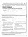
[] It is recommended that the owner post, in a prominent location, instructions for the customer's use in the event the customer smells
gas. This information should be obtained from your gas supplier.
[] Post the following warning in a prominent location.
I FOR YOUR SAFETY
Do not store or use gasoline or other flammable vapors and liquids in the vicinity of this or any other appliance.

WARNING: For your safety, the information in this manual must be followed to minimize
the risk of fire or explosion, or to prevent property damage, personal injury, or death. J
= Do not store or use gasoline or other flammable vapors and liquids in the vicinity of this
or any other appliance.
= WHAT TO DO iF YOU SMELL GAS:
• Do not try to light any appliance.
• Do not touch any electrical switch; do not use any phone in your building.
• Clear the room, building, or area of all occupants.
• immediately call your gas supplier from a neighbor's phone. Follow the gas supplier's
instructions.
• if you cannot reach your gas supplier, call the fire department.
= installation and service must be performed by a qualified installer, service agency, or
the gas supplier.
In the State of Massachusetts, the following installation instructions apply:
[] Installations and repairs must be performed by a qualified or licensed contractor, plumber, or gasfitter qualified or licensed by
the State of Massachusetts.
[] If using a ball valve, it shall be a T-handle type.
[] A flexible gas connector, when used, must not exceed 3 feet.
iMPORTANT SAFETY INSTRUCTIONS
WARNING: To reduce the risk of fire, electric shock, or injury to persons when using the dryer, follow basic precautions,
including the following:
[]
[]
Read all instructions before using the dryer.
Do not place items exposed to cooking oils in your dryer.
Items contaminated with cooking oils may contribute to
a chemical reaction that could cause a load to catch fire.
Do not repair or replace any part of the dryer or attempt
any servicing unless specifically recommended in this
Use and Care Guide or in published user-repair instruc-
tions that you understand and have the skills to carry out.
[] Do not dry articles that have been previously cleaned in,
washed in, soaked in, or spotted with gasoline, dry-
cleaning solvents, other flammable, or explosive
substances as they give off vapors that could ignite or
explode.
[] Do not allow children to play on or in the dryer. Close
supervision of children is necessary when the dryer is
used near children.
[] Before the dryer is removed from service or discarded,
remove the door to the drying compartment.
[] Do not reach into the dryer if the drum is moving.
[] Do not install or store the dryer where it will be exposed
to the weather.
[] Do not tamper with controls.
[] Do not use fabric softeners or products to eliminate static
unless recommended by the manufacturer of the fabric
softener or product.
[] Do not use heat to dry articles containing foam rubber or
similarly textured rubber-like materials.
[] Clean lint screen before or after each load.
[] Keep area around the exhaust opening and adjacent sur-
rounding areas free from the accumulation of lint,dust,
and dirt.
[] The interior of the dryer and exhaust vent should be
cleaned periodically by qualified service personnel.
[] See installation instructions for grounding requirements.
SAVE THESE iNSTRUCTiONS
iMPORTANT: The gas installation must conform with local codes, or in the absence of local codes, with the National Fuel Gas
Code, ANSi Z223.1/NFPA 54 or the Canadian Natural Gas and Propane installation Code, CSA B149.1.
The dryer must be electrically grounded in accordance with local codes, or in the absence of local codes, with the National
Electrical Code, ANSI/NFPA 70 or Canadian Electrical Code, CSA O22.1.

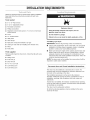
INST TION I QUI MENTS
Gather the required tools and parts before starting installation.
Read and follow the instructions provided with any tools
listed here.
Tools needed
[] 8" or 10" Pipewrench
[] 8' or 10" adjustable wrench
[] Flat-blade screwdriver
[] Phillips screwdriver
[] Adjustable wrench that opens to 1" (2.5 cm) or hex-head
socket wrench
[] Level
[] %6"socket wrench
[] Utility knife
[] Vent clamps
[] Pipe-joint compound resistant to LP gas
[] Caulk gun and caulk (for installing new exhaust vent)
[] Pliers
[] Putty knife
Parts supplied
Remove parts bag from dryer drum. Check that all parts were
included.
[] Wedge cone
[] Foot boot (4)
[] Dryer foot (4)
[] %6"-18 x 21/2"bolt
[] 3 pin timing cam
[] 6 pin timing cam
Explosion Hazard
Keep flammable materials and vapors, such as
gasoline, away from dryer.
Do not install in a garage.
Failure to do so can result in death, explosion, or fire.
If installing a gas dryer:
iMPORTANT: Observe all governing codes and ordinances.
[] Check code requirements: Some codes limit or do not permit
installation of clothes dryers in garages, closets, or sleeping
quarters. Contact your local building inspector.
[] Make sure that lower edges of the cabinet, plus the back and
bottom sides of the dryer, are free of obstructions to permit
adequate clearance of air openings for combustion air. See
"Recessed Area and Closet Installation Instructions" below for
minimum spacing requirements.
NOTE: The dryer must not be installed in an area where it will be
exposed to water and/or weather.
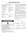
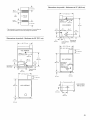
Recessed Area and Closet Installation Instructions
This dryer may be installed in a recessed area or closet. For
recessed area and closet installations, minimum clearances can
be found on the serial tag on the dryer.
The installation spacing is in inches and is the minimum
allowable. Additional spacing should be considered for ease of
installation, servicing, and compliance with local codes and
ordinances.
If closet door is installed, the minimum unobstructed air opening
in the top and bottom is required. Louvered doors with equivalent
air openings are acceptable.
The dryer must be exhausted outdoors.
No other fuel-burning appliance may be installed in the same
closet as the dryer.

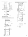
Minimum Installation Clearances
15"
(38.1 crn)*
f
0" (0crn)
!__
oIo
0" (0 crn)
Recessed front view
14"-- _
(35.6 crn)
max.
Closet
door
-- 5 crn)
Closet side view
Additional clearances for wall, door and floor moldings may be required or if
external exhaust elbow is used.
48 in2.
(310crn2)*
Front
View
24 in2
(155 crn2)*
O closet
door
*Opening is the minimum for a closet door.
3" (7.6 crn)
3" (7.6 crn)
Louvered doors with equivalent air openings are acceptable.
i
Product Dimensions 29" (73.7 cm) dryer
t
35"
(88.9 crn)
(2.5 crn)_
_-_ 29" (73.7 crn)
1
I
BACK VIEW
ELECTRIC _ .......
(40.8 crn)
271/4"
13" 4" (10.2 crn) (69.2 crn)
_-x_;_-.v__ s_....
?,_, N Hk
18%" _i
/
(46.7 crn)
(64.8 crn)
251/2"
I 77/8" (20 crn)
[
SIDE VIEW
O
Product Dimensions 27" (68.6 cm) dryer
_,:_ 27" (68.6 crn)
I
.........r
ELECTRIC_ I
(35.6 crn) /
37"
BACK VIEW (94crn)
6_4" 13" 4" (10.2 Crn)
(15_ _-_E dia, 43/4"
,/ (12.1 cnl)
...... _AS " P"
i _2_T.....L
(3.2 crn)
35"
(88.9 crn)
1"
(2.5 crn)
,_-_ 29_/4"(74.3 crn)_
(67.3 crn) _1
=
261/2"
I------"3
I
I
I
SIDE VIEW
10V4"
LEFT OR
RIGHT SIDE i
EXHAOST@_. _
zs A'7_
T
4V4"
(10.8 crn)
" (20 crn)
71_
(18.4 crn)
14W'
(35.9crn)
BOTTOM
i EXHAUST
\
\

ii i{]i{iiiie ;ii£@:; i! iiz = ,iiiiiii ii i
Electrical Shock Hazard
Plug into a grounded 3 prong outlet.
Do not remove ground prong.
Do not use an adapter.
Do not use an extension cord.
Failure to fellow these instructions can result in death,
fire, or electrical shock.
iMPORTANT: The dryer must be electrically grounded in
accordance with local codes and ordinances or, in the absence of
local codes, with the National Electrical Code, ANSI/NFPA 70,
latest edition, or Canadian Electrical Code, CSA C22.1.
If codes permit and a separate ground wire is used, it is
recommended that a qualified electrical installer determine that
the ground path is adequate.
A copy of the above code standards can be obtained from:
National Fire Protection Association
One Batterymarch Park, Quincy, MA 02269
CSA International
8501 East Pleasant Valley Road
Cleveland, Ohio 44131-5575
[] A 120 volt, 60 Hz, AC only, 15- or 20-amp, fused electrical
circuit is required. A time-delay fuse or circuit breaker is also
recommended. It is recommended that a separate circuit
serving only this dryer be provided.
Recommended Ground Method
The dryer, when installed, must be electrically grounded in
accordance with local codes or, in the absence of local codes,
with the National Electrical Code, ANSI/NFPA 70, latest edition,
or Canadian Electrical Code, CSA C22.1, and all local codes and
ordinances.
GROUNDING iNSTRUCTiONS
[] For a grounded, cord-connected dryer:
This dryer must be grounded. In the event of a malfunction or
breakdown, grounding will reduce the risk of electric shock
by providing a path of least resistance for electric current.
This dryer is equipped with a cord having an equipment-
grounding conductor and a grounding plug. The plug must be
plugged into an appropriate outlet that is properly installed
and grounded in accordance with all local codes and
ordinances.
WARNING: Improper connection of the equipment-
grounding conductor can result in a risk of electric shock.
Check with a qualified electrician or service representative or
personnel if you are in doubt as to whether the dryer is
properly grounded. Do not modify the plug provided with the
dryer: if it will net fit the outlet, have a proper outlet installed
by a qualified electrician.
SAVE THESE iNSTRUCTiONS
IMPORTANT: The dryer must be electrically grounded in
accordance with local codes and ordinances or, in the absence
of local codes, with the National Electrical Code, ANSI/NFPA 70,
latest edition, or Canadian Electrical Code, CSA C22.1.
The National Electric Code requires a 4-wire supply connection
for homes built after 1996, dryer circuits involved in remodeling
after 1996, and all mobile home installations.
If codes permit and a separate ground wire is used, it is
recommended that a qualified electrical installer determine that
the ground path is adequate.
A copy of the above code standards can be obtained from:
National Fire Protection Association
One Batterymarch Park, Quincy, MA 02269
CSA International
8501 East Pleasant Valley Road
Cleveland, Ohio 44131-5575
[] In U.S.: A four-wire or three-wire, single-phase, 120/240 volt,
60 Hz, AC only electrical supply (or four-wire or three-wire,
120/208 volt, if specified on the model/serial rating plate) is
required on a separate, 30-amp circuit, fused on both sides of
the line. A time-delay fuse or circuit breaker is recommended.
[] In Canada: A four-wire only, single phase 115/230 volt, 60 Hz
electrical supply is required on a separate, 30-amp circuit,
fused on both sides of the line. A time-delay fuse or circuit
breaker is recommended.

Recommended Ground Method
[] In U.S.: It is your responsibility to contact a qualified electrical
installer to ensure that the electrical installation is adequate
and in conformance with the National Electrical Code,
ANSI/NFPA 70, latest edition, and all local codes and
ordinances.
[] In Canada: It is your responsibility to install the dryer in
accordance with Canadian Electrical Code, CSA C22.1
installation codes and all national or local codes.
Canadian models are equipped with a four-wire, 30-amp rated
flexible-type power cord. The power cord must be plugged
into a mating 30-amp receptacle.
GROUNDING iNSTRUCTiONS
[] For a grounded, cord-connected dryer:
This dryer must be grounded. In the event of a malfunction or
breakdown, grounding will reduce the risk of electric shock
by providing a path of least resistance for electric current.
This dryer uses a cord having an equipment-grounding
conductor and a grounding plug. The plug must be plugged
into an appropriate outlet that is properly installed and
grounded in accordance with all local codes and ordinances.
[] For a permanently connected dryer:
This dryer must be connected to a grounded metal,
permanent wiring system, or an equipment-grounding
conductor must be run with the circuit conductors and
connected to the equipment-grounding terminal or lead on
the dryer.
WARNING: Improper connection of the equipment-
grounding conductor can result in a risk of electric shock.
Check with a qualified electrician or service representative or
personnel if you are in doubt as to whether the dryer is
properly grounded. Do not modify the plug on the power
supply cord: if it will not fit the outlet, have a proper outlet
installed by a qualified electrician.
SAVE THESE iNSTRUCTiONS
Explosion Hazard
Use a new CSA International approved gas supply line.
install a shut-off valve.
Securely tighten all gas connections.
if connected to LP, have a qualified person make sure
gas pressure does not exceed 14" (36 cm) water
column.
Examples of a qualified person include:
licensed heating personnel,
authorized gas company personnel, and
authorized service personnel.
Failure to do so can result in death, explosion, or fire.
iMPORTANT: Observe all governing codes and ordinances.
This installation must conform with all local codes and
ordinances. In the absence of local codes, installation must
conform with American National Standard, National Fuel Gas
Code ANSI Z223.1/NFPA 54 or CAN/CSA B149.
A copy of the above code standards can be obtained from:
National Fire Protection Association
One Batterymarch Park, Quincy, MA 02269
CSA International
8501 East Pleasant Valley Road
Cleveland, Ohio 44131-5575
The design of this dryer has been certified by CSA International
for use at altitudes up to 10,000 feet (3048 m) above sea level at
the B.T.U. rating indicated on the model/serial plate. Burner input
adjustments are not required when the dryer is operated up to
this elevation.
When installed above 10,000 feet (3048 m), a four percent (4%)
reduction of the burner B.T.U. rating shown on the model/serial
plate is required for each 1,000 foot (305 m) increase in elevation.
For assistance when converting to other gas types and/or
installing above 10,000 feet (3048 m) elevation, contact your local
service company.
Type of Gas
This dryer is equipped for use with natural gas. It is design-
certified by CSA International for LP (propane and butane) gases
with appropriate conversion. No attempt shall be made to convert
the dryer from the gas specified on the serial/rating plate for use
with a different gas without consulting the serving gas supplier.
Conversion must be done by a qualified service technician. Gas
conversion kit part numbers are listed on the gas valve burner
base.

GasSupply Line
Recommended method
[] Provide a gas supply line of 1/2"rigid (IPS) pipe to the dryer
location. Pipe joint compounds that resist the action of LP gas
must be used. Do not use TEFLON_t tape. With LP gas,
piping or tubing size can be r/2" minimum. Usually, LP gas
suppliers determine the size and materials used in the system.
Alternate method
[] The gas supply may also be connected using %" approved
copper or aluminum tubing. If the total length of the supply
line is more than 20 ft. (6.1 m), larger tubing will be required. If
using natural gas, do not use copper tubing. Pipe joint
compounds that resist the action of LP gas must be used.
Flexible metal appliance connector:
[] It is recommended that a new flexible stainless steel gas line,
design-certified by CSA International, be used for connecting
the dryer to the gas supply line. (The gas pipe which extends
through the lower rear of the dryer is provided with 3/8"male
pipe thread.)
[] Do not kink or damage the flexible stainless steel gas line
when moving the dryer.
Rigid pipe connection:
The rigid pipe connection requires a combination of pipe fittings
to obtain an in-line connection to the dryer.
[] Must include a shutoff valve:
The supply line must be equipped with a manual shutoff valve
installed within 6 ft. (1.8 m) of dryer in accordance with
National Fuel Gas Code, ANSI Z223.1. In Canada, an
individual manual shutoff valve must be installed in
accordance with the B149 installation codes CAN/CGA
B149.1 and CAN/CGA B149.2. This valve should be located in
the same room as the dryer. It should be in a location that
allows ease of opening and closing. Do not block access to
shutoff valve. The valve is for turning on or shutting off gas to
the dryer.
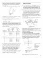
B
A. Gas supply line
B. Shutoff valve "open" position
C. To dryer
1-(8)TEFLON is a registered trademark of E.I. Du Pont De Nemours and Company.
Installed in a confined area:
Ifthe dryer is installed in a confined area such as a bathroom
or closet, provision must be made for enough air for
combustion and ventilation. Check governing codes and
ordinances or refer to the "Recessed Area and Closet
Installation Instructions" in the "Location Requirements"
section.
Gas Supply Pressure Testing
A 1/8"NPT minimum plugged tapping, accessible for gauge
testing, must be installed immediately upstream of the gas supply
connection to the dryer.
The dryer must be disconnected from the gas supply piping
system during any pressure testing of the system at test
pressures in excess of 1/2psig.
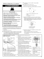
Fire Hazard
Use a heavy metal vent.
Do not use a plastic vent.
Do not use a metal foil vent.
Failure to follow these instructions can result in death
or fire.
WARNING: To reduce the risk of fire, this dryer MUST BE
EXHAUSTED OUTDOORS.
[] The dryer vent must not be connected into any gas vent,
chimney, wall, ceiling, or a concealed space of a building.
[] Do not use an exhaust hood with a magnetic latch.
[] Do not install flexible metal vent in enclosed walls, ceilings or
floors.
[] 4" (10.2 cm) heavy metal vent and clamps must be used.
[] Use clamps to seal all joints. Vent must not be connected or
secured with screws or other fastening devices which extend
into the interior of the vent. Do not use duct tape.
IMPORTANT: Observe all governing codes and ordinances.
Use a heavy metal vent. Do not use plastic or metal foil vent.
Rigid metal vent is recommended to prevent crushing and
kinking.
Flexible metal vent must be fully extended and supported when
the dryer is in its final position. Remove excess flexible metal vent
to avoid sagging and kinking that may result in reduced airflow
and poor performance.
An exhaust hood should cap the vent to prevent rodents and
insects from entering the home or business.
Exhaust hood must be at least 12" (30.5 cm) from the ground or
any object that may be in the path of the exhaust (such as
flowers, rocks or bushes).

Ifusinganexistingventsystem,cleanlintfromtheentirelength
ofthesystemandmakesureexhausthoodisnotpluggedwith
lint.Replaceanyplasticormetalfoilventwithrigidmetalor
flexiblemetalvent.
Planinstallationtousethefewestnumberofelbowsandturns.
ExhaustAirFlow
A.Better
B.Good
Allow as much room as possible when using elbows or making
turns. Bend vent gradually to avoid kinking.
Vent outlet is located at the center of the bottom dryer back.
The vent can be routed up, down, left, right, behind the dryer or
straight out the back of the dryer.
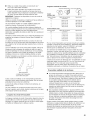
Vent System Length
Maximum length of vent system depends upon the type of vent
used, number of elbows and type of exhaust hood. The maximum
length for both rigid and flexible vent is shown in the chart.
Maximum Vent Length
4" (10.2 cm) Diameter Exhaust Hoods
Rigid Metal Vent
No. of 90° turns Box Hood and Louvered Style Angled Hood Style
0 135 ft. (41.2 m) 129 ft. (39.3 rn)
1 125 ft. (38.1 m) 119 ft. (36.3 m)
2 115 ft. (35.1 m) 109 ft. (33.2 rn)
3 106 ft. (32.3 m) 100 ft. (30.5 rn)
4 98 ft. (29.9 m) 92 ft. (28.0 m)
Flexible Metal Vent
No. of 90° turns Box Hood and Louvered Style Angled Hood Style
0 76 ft. (23.2 rn) 62 ft. (18.9 rn)
1 71 ft. (21.6 m) 57 ft. (17.4 rn)
2 67 ft. (20.4 m) 53 ft. (16.2 rn)
3 65 ft. (19.8 rn) 51 ft. (15.6 m)
4 63 ft. (19.2 m) 49 ft. (14.9 rn)
For vent systems not covered by the vent specification chart, see
Whirlpool Service Manual, "Exhausting Whirlpool Dryers," Part
No. LIT603197, available from your Whirlpool parts distributor.
If dryer is installed in a confined area, such as a bedroom,
bathroom or closet, provision must be made for enough air for
combustion and ventilation. (Check governing codes and
ordinances.) See "Recessed Area and Closet Installation
Instructions" in the "Location Requiements" section.
A 4" (10.2 cm) outlet hood is preferred. However, a 21/2'' (6.4 cm)
outlet exhaust hood may be used. A 21A'' (6.4 cm) outlet creates
greater back pressure than other hood types. For permanent
installation, a stationary vent system is required.
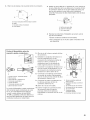
Multiple Dryer Venting
[] A main vent can be used for venting a group of dryers. Main
vent should be sized to remove 200 CFM of air per dryer.
Large-capacity lint screens of proper design may be used in
the main vent if checked and cleaned frequently. The room
where the dryers are located should have make-up air equal
to or greater than the CFM of all the dryers in the room.
[] Back-draft Damper Kit, Part No. 3391910, is available from
your Whirlpool dealer and should be installed in each dryer's
vent to prevent exhausted air from returning into the dryers
and to keep the exhaust in balance within the main vent.
Unobstructed air openings are required.
Each vent should enter the main vent at an angle pointing in the
direction of the airflow. Vents entering from the opposite side
should be staggered to reduce the exhausted air from interfering
with the other vents.
The maximum angle of each vent entering the main vent should
be no more than 30°.
A _
air flow _ B _._--
A.Individualdryervent
B.Mainvent
Keep air openings free of dry cleaning fluid fumes. Fumes create
acids which, when drawn through the dryer heating units, can
damage dryers and loads being dried.
A clean-out cover should be located on the main vent for periodic
cleaning of the vent system.
If an exhaust hood cannot be used:
The outside end of the main vent should have a sweep elbow
directed downward. If the main vent travels vertically through the
roof, rather than through the wall, install a 180° sweep elbow on
the end of the vent at least 2 ft. (61 cm) above the highest part of
the building. The opening wall or roof shall have a diameter 1/2"
(1.3 cm) larger than the vent diameter. The vent should be
centered in the opening.
B
A C
,,¢
jf
A.Exhausthoodorelbow
B.WallC.Maincollectorvent
D. Horizontalvent
E. t80°sweepelbow
E
F.Verticalvent
...........I I _ _t. (61 ore)rain, above
_ _ highest point of building
......e
Do not install screening or cap over the end of the vent.

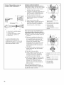
INSTALLATIONINSTRUCTIONS- GASDRYER
The console houses the factory-installed accumulator timer with t.
actuating arm and button. 2.
The factory-installed timer is set to provide 45 minutes (4 pins) of
drying time when activated by the coin slide. Timer cams for
30-minute (6 pins) and 60-minute (3 pins) drying times are
included in the parts bag.
The coin slide mechanism, control panel lock and key, and coin
box lock and key are not included and are available from usual
industry sources.
Excessive Weight Hazard
Use two or more people to move and install dryer.
Failure to do so can result in back or other injury.
NOTE: Slide dryer onto cardboard or hardboard before moving to
avoid damaging floor covering.
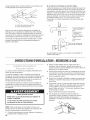
t. Using two or more people, move dryer to desired installation
location.
2. Take tape off front corners of dryer. Open dryer and remove
the literature and parts packages. Wipe the interior of the
drum thoroughly with a damp cloth.
3. Take two of the cardboard corners from the carton and place
them on the floor in back of the dryer. Firmly grasp the body
of the dryer and gently lay it on its back on the cardboard
corners.
4. With one of the legs in hand, check the ridges for a diamond
marking. That's how far the leg is supposed to go into the
hole.
5. Start to screw the leveling legs into the holes by hand. (Use a
small amount of liquid detergent to lubricate the screw
threads so it is easier to turn the legs.) Use a 1" wrench or
socket wrench to finish turning the legs until you reach the
diamond mark.
Now stand the dryer up.
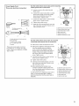
6. Remove the service door of the meter case by lifting it up at
the back. Install the money-accepting device. (Refer to
manufacturer's instructions for proper installation.)
For dryers using coin slides, use the adapter kit supplied with
the dryer.
7. Replace the meter case service door. Put the coin vault with
lock and key in the meter case opening.
8. Remove cardboard or hardboard from under dryer.
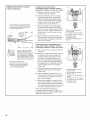
3=
4.
Remove red cap from gas pipe.
Connect gas supply to dryer. Use pipe-joint compound
resistant to the action of L.R gas for gas connections. If
flexible metal tubing is used, be certain there are no kinks.
If necessary for service, open the toe panel. Use a putty knife
to press on the toe panel lock located at the center top of the
toe panel. Pull downward on the toe panel to open. Toe panel
is hinged at the bottom.
Open the shutoff valve in the gas supply line.
Test all connections by brushing on an approved noncorrosive
leak-detection solution. Bubbles will show a leak. Correct any
leak found.
t. Using a 4" (10.2 cm) clamp, connect vent to exhaust outlet in
dryer. If connecting to existing vent, make sure the vent is
clean. The dryer vent must fit over the dryer exhaust outlet
and inside the exhaust hood. Make sure the vent is secured to
exhaust hood with a 4" (10.2 cm) clamp.
2. Move dryer into final position. Do not crush or kink vent. Make
sure dryer is level.
3. Check to be sure there are no kinks in the flexible gas line.
2=
3.
With dryer in final position place level on top of the dryer, first
side to side; then front to back. Ifthe dryer is not level, adjust
the legs of the dryer up or down until the dryer is level.
Electrical Shock Hazard
Plug into a grounded 3 prong outlet.
Do not remove ground prong.
Do not use an adapter.
Do not use an extension cord.
Failure to follow these instructions can result in death,
fire, or electrical shock.
Plug into a grounded 3 prong outlet.
Check dryer operation (some accumulated time may be on
the timer due to factory testing).
Insert coins in slide and press slide in slowly. (Operating time
will accumulate per number of coins and type of timing cam
used.) Push START/RESTART button. Using a full heat cycle
10

(not the air cycle), let the dryer run for at least five minutes.
Dryer will stop when time is used up.
NOTE: Dryer door must be closed for dryer to operate. When
door is open, dryer stops, but timer continues to run. To
restart dryer, close door and push START/RESTART button.
4. Ifthe burner does not ignite and you can feel no heat inside
the dryer, shut off dryer for five minutes. Check that all supply
valve controls are in "ON" position and that the electrical cord
is plugged in. Repeat five-minute test.
5. If drying time is too long, make sure lint screen is clean.
INST TION INSTRUCTIONS-ELECTRICDRYER
The console houses the factory-installed accumulator timer with
actuating arm and button.
The factory-installed timer is set to provide 45 minutes (4 pins) of
drying time when activated by the coin slide. Timer cams for
30-minute (6 pins) and 60-minute (3 pins) drying times are
included in the parts bag.
The coin slide mechanism, control panel lock and key, and coin
box lock and key are not included and are available from usual
industry sources.
Excessive Weight Hazard
Use two or more people to move and install dryer.
Failure to do so can result in back or other injury.
NOTE: Slide dryer onto cardboard or hardboard before moving to
avoid damaging floor covering.
1. Using two or more people, move dryer to desired installation
location.
2. Take tape off front corners of dryer. Open dryer and remove
the literature and parts packages. Wipe the interior of the
drum thoroughly with a damp cloth.
3. Take two of the cardboard corners from the carton and place
them on the floor in back of the dryer. Firmly grasp the body
of the dryer and gently lay it on its back on the cardboard
corners.
4. With one of the legs in hand, check the ridges for a diamond
marking. That's how far the leg is supposed to go into the
hole.
5. Start to screw the leveling legs into the holes by hand. (Use a
small amount of liquid detergent to lubricate the screw
threads so it is easier to turn the legs.) Use a 1" wrench or
socket wrench to finish turning the legs until you reach the
diamond mark.
Now stand the dryer up.
6. Remove the service door of the meter case by lifting it up at
the back. Install the money-accepting device. (Refer to
manufacturer's instructions for proper installation.)
7. Replace the meter case service door. Put the coin vault with
lock and key in the meter case opening.
8. Remove cardboard or hardboard from under dryer.
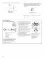
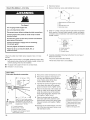
Power Supply Cord Method - U.S. Only
This dryer is manufactured with the neutral ground wire
connected to the neutral (center) of the wiring harness at the
terminal block. If local codes do not permit this type of
connection, use "Four-wire connection" instructions.
Use a UL-listed power supply cord rated 240 volt min.,
30-amp and marked for use with a clothes dryer.
Fire Hazard
Use a new UL listed 30 amp power supply cord.
Use a UL listed strain relief.
Disconnect power before making electrical connections.
Connect neutral wire (white or center wire) to center
terminal (silver).
Ground wire (green or bare wire) must be connected to
green ground connector.
Connect remaining 2 supply wires to remaining
2 terminals (gold).
Securely tighten all electrical connections.
Failure to de so can result in death, fire, or
electrical shock.
t. Disconnect power.
For dryers using coin slides, use the adapter kit supplied with
the dryer.
11

2. Removehold-downscrewandtheterminalblockcover.
_D
3=
Assemble 3/4"UL-listed strain relief (UL marking on strain
relief) into the hole below the terminal block opening. Tighten
strain relief screws just enough to hold the two clamp
sections together. Install power supply cord through the
strain relief.
A. External ground conductor screw
B. Tab
C. Terminalblock cover
D. Hold-down screw
4=
A. Strain relief clamp sections
B. Dryer cabinet
C. Strain relief screws
Complete installation following instructions for your type of
electrical connection:
• Four-wire (recommended method)
Three-wire (iffour-wire is not available)
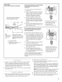
Power Supply Cord,
Four-wire electrical connection:
B
G
C D
f
A.Spadeterminalswithupturnedends E
B.Neutral
C.3/4"UL-listedstrainrelief
D.Neutral(white)
E. Ringterminals
E Groundwire
G.Groundprong
Four-wire power supply cord must have four,
No. 10 copper wires and match a four-wire
receptacle of NEMA Type 14-30R. The
fourth wire (ground conductor) must be
identified by a green cover and the neutral
conductor by a white cover.
5. Remove the center terminal block screw.
6. Remove the appliance neutral ground wire
from the external ground conductor screw.
Fasten under center, silver-colored
terminal block screw.
7. Connect the ground wire of the power
supply cord to the external ground
conductor screw. Tighten screw.
8. Connect the neutral wire (white or center)
of the power supply cord under the center
screw of the terminal block. Tighten
screw.
9. Connect the other wires to outer terminal
block screws. Tighten screws.
t0. Tighten strain relief screws.
t 1. Insert tab of the terminal block cover into
slot of the dryer rear panel. Secure cover
with hold-down screw.
A. External ground conductor screw
B. Appliance neutral ground wire
C. Center terminal block screw
D. Outer terminal block screws
E. Strain relief screw
E Neutral (center wire)
G. Ground wire
12

Power Supply Cord,
Three=wire electrical connection:
Thisbladeconnectedto B
.....thisconductor. ........................
E D C
A. Spade terminals with upturned ends
B. Ring terminals
C.Neutral (white or center)
D. 3/4"UL-listed strain relief
E. Neutral
Three-wire power supply cord must
have three, No. 10 copper wires and
match a three-wire receptacle of NEMA
Type 10-30R.
Use this method where local codes permit connecting
neutral ground wire to neutral wire: A ....................
I_] _
5. Loosen or remove the center terminal F-'__
block screw. F ......
0
E ............
Connect the neutral wire (white or center)
of the power supply cord to the center,
silver-colored terminal screw of the
terminal block. Tighten screw.
7. Connect the other wires to outer terminal
block screws. Tighten screws. _ C
8. Tighten strain relief screws.
9. Insert tab of the terminal block cover into D............
slot of the dryer rear panel. Secure cover
with hold-down screw.
A. External ground conductor screw
B.Center terminal block screw
C.Outer terminal block screws
D. Strain relief screw
E. Neutral (center wire)
F.Appliance neutral ground wire
Use this method where local codes do not permit
connecting neutral ground wire to neutral wire:
5. Remove the center terminal block screw.
6. Remove the appliance neutral ground wire
from the external ground conductor
screw. Connect the appliance neutral
ground wire and the neutral wire (white or
center) of the power supply cord under
the center, silver-colored terminal block
screw. Tighten screw.
7. Connect the other wires to outer terminal
block screws. Tighten screws.
8. Tighten strain relief screws.
9. Insert tab of the terminal block cover into
slot of the dryer rear panel. Secure cover
with hold-down screw.
t0. After reattaching the terminal cover,
connect a separate copper ground wire
from the external ground conductor screw
to an adequate ground.
If codes permit and a separate ground wire is
used, it is recommended that a qualified
electrician determine that the ground path is
adequate.
A. Separate copper ground wire
B. Extemat ground conductor screw
C. Appliance neutral ground wire
D. Center terminal block screw
E. Outer terminal block screws
F. Strain relief screw
G. Neutral (center wire)
13

1. Disconnect power.
Direct Wire Method - U.S. Only 2. Remove hold-down screw and terminal block cover.
Fire Hazard
Use 10 gauge solid copper wire.
Use a UL listed strain relief.
Disconnect power before making electrical connectione.
Connect neutral wire (white or center wire) to center
terminal (silver).
Ground wire (green or bare wire) must be connected to
green ground connector.
Connect remaining 2 supply wires to remaining
2 terminals (gold).
Securely tighten all electrical connections.
Failure to do so can result in death, fire, or
electrical shock.
Direct wire cable must match power supply (4-wire or 3-wire)
and be:
[] Flexible armored cable or nonmetallic sheathed copper cable
(with ground wire), protected with flexible metallic conduit. All
current-carrying wires must be insulated.
[] 10-gauge solid copper wire (do not use aluminum).
[] At least 5 ft. (1.52 m) long.
...... 0
_f
3=
A. External ground conductor screw
B. Tab
C. Terminalblock cover
D. Hold-down screw
Install 3/4"conduit connector into the hole below the terminal
block opening. Connect flexible metallic conduit and tighten
connector screw. Install direct wire cable through the flexible
metallic conduit.
!
_J
B
4=
A. Conduit connector
B. Dryer cabinet
C. Connector screw
Complete installation following instructions for your type of
electrical connection:
• Four-wire (recommended method)
Three-wire (iffour-wire is not available)
Direct Wire,
Four=wire electrical connection:
"_ 31/2"(8.9 crn) _l
/
A 1" (2.5 crn) --{_-
I of wires | I
to I stripped of |
_ 5" (t2,7 crn) _
Strip 5" (12.7 crn) of outer covering
from end of cable. Leave green or bare
Shape ends ground wire at 5" (12.7 crn). Cut 1½"
of wires into (3.8 crn) from 3 remaining wires. Strip
a hook. insulation back 1" (2.5 crn).
A. _4" conduit connector
B. Neutral (white or center)
C. Ground wire (green or bare)
D. tO-gauge, 3 wire with ground wire in
flexible metallic conduit
5. Remove the center terminal block screw.
6. Remove the appliance neutral ground
wire from the external ground conductor
screw. Fasten under center, silver-
colored terminal block screw.
7. Connect the ground wire (green or bare)
of the direct wire cable to the external
ground conductor screw. Tighten screw.
8. Place the hooked end of the neutral wire
(white or center) of the direct wire cable
under the center screw of the terminal
block (hook facing right). Squeeze hook
end together. Tighten screw.
9. Place the hooked ends of the other
direct wire cable wires under the outer
terminal block screws (hook facing right).
Squeeze hooked ends together. Tighten
screws.
t0. Insert tab of the terminal block cover into
slot of the dryer rear panel. Secure cover
with hold-down screw.
E
D
A. External ground conductor screw
B. Appliance neutral ground wire
C. Center terminal block screw
D. Outer terminal block screws
E. Neutral (center wire)
F. Green or bare ground wire
14

Direct Wire,
Three=wire electrical connection:
Three wire with ground wire: green or bare
wire cut short. Wire is not used. Dryer is
grounded through neutral conductor.
A
ofwires
to stripped of
disconnect insulation
box
c
_ Shapeends
of wires into
a hook.
Strip 31_'' (8.9 cm) of outer
covering from end of cable. Strip
insulation back 1" (2.5 cm). If using
3 wire cable with ground wire, cut
green or bare wire even with outer
covering.
A. _4" conduit connector
B. Neutral (white or center)
C. tO-gauge, 3 wire with ground wire in
flexible metallic conduit
Use this method where local codes permit
connecting neutral ground wire to
neutral wire:
5. Loosen or remove the center terminal
block screw.
6. Place the hooked end of the neutral wire
(white or center) of the direct wire cable
under the center screw of the terminal
block (hook facing right). Squeeze
hooked end together. Tighten screw.
7. Place the hooked ends of the other
direct wire cable wires under the outer
terminal block screws (hook facing right).
Squeeze hooked ends together. Tighten
screws.
8. Insert tab of the terminal block cover into
slot of the dryer rear panel. Secure cover
with hold-down screw.
.....,...............................
A. Extemat ground conductor screw
B. Center terminal block screw
C. Outer terminal block screws
D. Neutral (center wire)
E.Appliance neutral ground wire
Use this method where local codes do
not permit connecting neutral ground
wire to neutral wire:
5. Remove the center terminal block screw.
6. Remove the appliance neutral ground wire
from the external ground conductor screw.
Connect the appliance neutral ground wire
and the neutral wire (white or center) of the
direct wire cable under the center, silver-
colored terminal block screw. Tighten
screw.
7. Connect the other wires to outer terminal
block screws. Tighten screws.
8. Insert tab of the terminal block cover into
slot of the dryer rear panel. Secure cover
with hold-down screw.
9. After reattaching the terminal cover,
connect a separate copper ground wire
from the external ground connector screw
to an adequate ground.
If codes permit and a separate ground wire is
used, it is recommended that a qualified
electrician determine that the ground path is
adequate.
A...........Ii C
A. Separate copper ground wire
B. External ground conductor screw
C. Appliance neutral ground wire
D. Center terminal block screw
E. Outer terminal block screws
t_ Neutral (center wire)
t. Using a 4" (10.2 cm) clamp, connect vent to exhaust outlet in
dryer. If connecting to existing vent, make sure the vent is
clean. The dryer vent must fit over the dryer exhaust outlet
and inside the exhaust hood. Make sure the vent is secured to
exhaust hood with a 4" (10.2 cm) clamp.
2. Move dryer into final position. Do not crush or kink vent. Make
sure dryer is level.
With dryer in final position place level on top of the dryer, first
side to side; then front to back. If the dryer is not level, adjust
the legs of the dryer up or down until the dryer is level.
2. Plug in dryer or reconnect power.
3. Check dryer operation (some accumulated time may be on
the timer due to factory testing).
Insert coins in slide and press slide in slowly. (Operating time
will accumulate per number of coins and type of timing cam
used.) Push START/RESTART button. Using a full heat cycle
(not the air cycle), let the dryer run for at least five minutes.
Dryer will stop when time is used up.
NOTE: Dryer door must be closed for dryer to operate. When
door is open, dryer stops, but timer continues to run. To
restart dryer, close door and push START/RESTART button.
4. If drying time is too long, make sure lint screen is clean.
5. Now start the dryer and allow it to complete a full heat cycle
(not air cycle) to make sure it is working properly.
15

CHANGINGTOA30-OR
60- NUTE TI NG CAM
Electrical Shock Hazard
Disconnect power before making cam changes.
Failure to follow these instructions can result in death
or electrical shock.
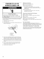
You can install the 30-minute or 60-minute timing cam (shipped
with dryer) as follows:
t. Unplug dryer or disconnect power.
2. Unlock meter case.
3. Turn the timing cam by hand until the V-shaped notch lines up
below the ratchet tooth.
.... C
........"_' b
A. RatchettoOtn_
B.Timingcam
C.Drivelug
D. V-shapednotch
4. Insert a narrow, flat-blade screwdriver under the timing cam
near the clock shaft. Gently lift cam straight up and off shaft
making sure that the V-shaped notch clears the ratchet tooth.
5. Place new cam (hub side down) over clock shaft. Line up flat
side of shaft with flat side of cam hole. Check that drive lug is
in place.
6. Turn cam until V-shaped notch lines up with ratchet tooth.
7. Press cam down in place on motor shaft. Make sure that
V-shaped notch clears the ratchet tooth.
8. Close and lock the meter case.
Maintenance instructions:
[] Clean lint screen after each cycle.
[] Removing accumulated lint:
[] From inside the dryer cabinet:
Lint should be removed every 2 years or more often,
depending on dryer usage. Cleaning should be done by a
qualified person.
[] From the exhaust vent:
Lint should be removed every 2 years, or more often,
depending on dryer usage.
If dryer does not operate check the following:
[] Electric supply is connected.
[] Circuit breaker is not tripped or house fuse is not blown.
[] Door is closed.
[] Controls are set in a running or "ON" position.
[] START button has been pushed firmly.
[] For gas dryers, check that gas supply shutoff valves are set in
open position.
If you need assistance:
The Commercial Laundry Support Center will answer any
questions about operating or maintaining your dryer not covered
in the Installation instructions. The Commercial Laundry Support
Center is open 24 hours a day, 7 days a week. Just dial
1-800 NO BELTS (1-800-662-3587) -- the call is toll free.
When you call, you will need the dryer model number and serial
number. Both numbers can be found on the serial-rating plate
located in the dryer door well.
16

MAYTAG COMMERCIAL WASHER, DRYER, STACKED DRYER/
DRYER, COMMERCIAL STACK LAUNDRY, AND MULTI-LOAD
COIN OPERATED COMMERCIAL WASHERS AND DRYERS
WARRANTY
LiMiTED WARRANTY ON PARTS
For the first five years from the date of purchase, when this commercial appliance is installed, maintained and operated according to the
instructions attached to or furnished with the product, Maytag brand of Whirlpool Corporation (thereafter Maytag ") will pay for factory
specified parts or original equipment manufacturer parts to correct defects in materials or workmanship. Proof of original purchase date
is required to obtain service under this warranty.
ITEMS MAYTAG WILL NOT PAY FOR
1. All other costs including labor, transportation, or custom duties.
2o Service calls to correct the installation of your commercial appliance, to instruct you how to use your commercial appliance, to
replace or repair fuses, or to correct external wiring or plumbing.
3o Repairs when your commercial appliance is used for other than normal, commercial use.
4o Damage resulting from improper handling of product during delivery, theft, accident, alteration, misuse, abuse, fire, flood, acts of
God, improper installation, installation not in accordance with local electrical or plumbing codes, or use of products not approved
by Maytag.
5o Pickup and Delivery. This commercial appliance is designed to be repaired on location.
6o Repairs to parts or systems resulting from unauthorized modifications made to the commercial appliance.
7o The removal and reinstallation of your commercial appliance if it is installed in an inaccessible location or is not installed in
accordance with published installation instructions.
8o Chemical damage is excluded from all warranty coverage.
9o Changes to the building, room, or location needed in order to make the commercial appliance operate correctly.
DiSCLAiMER OF iMPLiED WARRANTIES; LiMiTATiONS OF REMEDIES
CUSTOMER'S SOLE AND EXCLUSIVE REMEDY UNDER THIS LIMITED WARRANTY SHALL BE PRODUCT REPAIR AS PROVIDED
HEREIN. IMPLIED WARRANTIES, INCLUDING WARRANTIES OF MERCHANTABILITY OR FITNESS FOR A PARTICULAR PURPOSE,
ARE LIMITED TO ONE YEAR OR THE SHORTEST PERIOD ALLOWED BY LAW. WHIRLPOOL SHALL NOT BE LIABLE FOR
INCIDENTAL OR CONSEQUENTIAL DAMAGES. SOME STATES AND PROVINCES DO NOT ALLOW THE EXCLUSION OR LIMITATION
OF INCIDENTAL OR CONSEQUENTIAL DAMAGES, OR LIMITATIONS ON THE DURATION OF IMPLIED WARRANTIES OF
MERCHANTABEITY OR FITNESS, SO THESE EXCLUSIONS OR LiMITATiONS MAY NOT APPLY TO YOU. THIS WARRANTY GIVES
YOU SPECIFIC LEGAL RIGHTS AND YOU MAY ALSO HAVE OTHER RIGHTS, WHICH VARY FROM STATETO STATE OR PROVINCE
TO PROVINCE.
If you need service, please contact your authorized Maytag Commercial Laundry distributor. To locate your authorized Maytag
Commercial Laundry distributor, or for web inquiries, visit www.MaytagCommercialLaundry.com.
9/07
For written correspondence:
Maytag Commercial Laundry Service Department
2000 M-63 North
Benton Harbor, Michigan 49085 USA
17

# # #
SECURITEDELASECI USE
Votre s_curit_ et celle des autres est tr_s importante.
Nous donnons de nombreux messages de securite importants dans ce manuel et sur votre appareil menager. Assurez-vous de
toujours lire tousles messages de securite et de vous y conformer.
Voici le symbole d'alerte de securite.
Ce symbole d'alerte de securite vous signale les dangers potentiels de deces et de blessures graves & vous
et & d'autres.
Tous les messages de securite suivront le symbole d'alerte de securite et le mot "DANGER" ou
"AVERTISSEMENT". Ces mots signifient :
Risque possible de deces ou de blessure grave si vous ne
suivez pas immediatement lee instructions.
Risque possible de deces ou de blessure grave si vous
ne euivez pas lee instructions.
Tousles messages de securite vous diront quel est le danger potentiel et vous disent comment reduire le risque de blessure et
ce qui peut se produire en cas de non-respect des instructions.
[] On recommande que le proprietaire place les instructions & I'usage du client & un endroit bien visible, pour le cas oQ le client
percevrait une odeur de gaz. Ces renseignements doivent _tre obtenus aupres de votre fournisseur de gaz.
[] Placer I'avertissement qui suit a un endroit bien visible.
POU RVOTRE SleCURITle
Ne pas entreposer ni utiliser de I'essence ou d'autres produits liquides ou gazeux inflammables _.proximite de cet appareil ou de
tout autre appareil electromenager.
AVERTISSEMENT : Pour votre s_curit_, lee renseignements dane ce manuel doivent
_tre observes pour r_duire au minimum lee risques d'incendie ou d'e×plosion ou pour
_viter des dommages au produit, des blessures ou un d_ces.
= Ne pas entreposer ou utiliser de I'essence ou d'autres vapeurs ou liquides
inflammables a pro×imit_ de cet appareil ou de tout autre appareil _lectrom_nager.
= QUE FAIRE DANS LE CAS D'UNE ODEUR DE GAZ :
= Ne pas tenter d'allumer un appareil.
• Ne pas toucher a un commutateur _lectrique; ne pas utiliser le t_l_phone se trouvant
sur lee lieu×.
levacuer tous lee gens de la pi#ce, de I'edifice ou du quarrier.
Appeler imm_diatement le fournisseur de gaz d'un t_l_phone voisin. Suivre see
instructions.
._ d_faut de joindre votre fournisseur de gaz, appeler lee pompiers.
= L'installation et I'entretien doivent _tre effectu_s par un installateur qualifi_, une
agence de service ou le fournisseur de gaz.
18

IMPORTANTES INSTRUCTIONS DE SI_CURITI_
AVERTISSEMENT : Pour r6duire le risque d'incendie, de choc electrique ou de blessure Iors de I'utilisation de
la secheuse, il convient d'observer certaines precautions el6mentaires dont les suivantes :
• Lire toutes les instructions avant d'utiliser la secheuse.
• Ne pas placer des articles exposes aux huiles de cuisson
dans votre secheuse. Les articles contamines par des
huiles de cuisson peuvent contribuer a une reaction
chimique qui pourrait causer a la charge de s'enflammer.
• Ne pas faire secher dans la machine des articles qui ont
deja et6 nettoyes, lav6s, imbibes, ou taches d'essence,
de solvants pour nettoyage a sec, d'autres substances
inflammables, ou de substances explosives puisqu'elles
degagent des vapeurs qui peuvent provoquer un
incendie ou une explosion.
• Ne pas permettre & des enfants de jouer sur ou &
I'interieur de la secheuse. Une surveillance etroite est
necessaire Iorsque la secheuse est utilisee pres d'eux.
• Avant d'enlever la secheuse du service ou la jeter, enlever
la porte du compartiment de sechage,
• Ne pas mettre la main dans la secheuse si le tambour est
en mouvement.
• Ne pas installer ni entreposer la secheuse oQelle sera
exposee aux intemp@ies.
• Ne pas jouer avec les commandes.
• Ne pas reparer ni remplacer une piece de la secheuse ou
essayer d'en faire I'entretien a moins d'une recommandation
specifique dans le guide d'utlilisation et d'entretien, ou
publiee dans les instructions de reparation par I'utilisateur
que vous comprenez et pouvez executer avec competence.
• Ne pas utiliser un produit assouplissant de tissu ou des
produits pour eliminer la statique a moins qu'ils ne soient
recommandes par le fabricant du produit assouplissant de
tissu ou du produit.
• Ne pas utiliser la chaleur pour faire secher des articles
fabriques avec du caoutchouc mousse ou des materiaux
semblables.
• Nettoyer le filtre a charpie avant et apres chaque charge.
• Ne pas laisser la charpie, la poussiere, ou la salete
s'accumuler autour du systeme d'evacuation ou autour de
I'appareil.
• Un nettoyage p&riodique de I'interieur de la s6cheuse et du
conduit d'6vacuation dolt _tre effectue par une personne
qualifiee.
• Voir les instructions d'installation pour les exigences de
liaison de I'appareil a la terre.
CONSERVF:7 CES INSTRUCTIONS
iMPORTANT : L'installation du gaz doit se conformer aux codes Iocaux, ou en I'absence de codes Iocaux, au code canadien
d'installation B149.1 du gaz naturel ou du propane.
La secheuse dolt _tre electriquement reliee a la terre conformement aux codes Iocaux, ou en I'absence de codes Iocaux, au Code
canadien de I'electricite, CSA C22.1.
19

EXIGENCESD INST TION
Rassembler les outils et pi_ces necessaires avant de commencer
I'installation. Lire et respecter les instructions d'installation
fournies avec chacun des outils de cette liste.
Outillage n_cessaire
[] Cle &tube de 8" ou 10" [] Bride de fixation
[] Cle & molette de 8" ou 10"
[] Tournevis & lame plate
[] Tournevis Phillips
[] Cle & molette avec
ouverture jusqu'& 1" (2,5
cm) ou cle & douille
hexagonale
[] Niveau
[] Cle & douille de 5/16"
[] Couteau utilitaire
[] Compose d'etancheite des
raccords filetes - resistant
au propane
[] Pistolet a calfeutrage et
compose de calfeutrage
(pour I'installation d'un
nouveau circuit
d'evacuation)
[] Pince
[] Couteau a mastic
Pi_ces fournies
Retirer le sac de pieces du tambour de la secheuse. Verifier la
presence de toutes les pieces.
[] Coin [] Came de minutage &
[] Patin (4) 3 broches
[] Pied de la secheuse (4) [] Came de minutage &
6 broches
[] Boulon de 5/16"-18 x 21/2''
[]
Veiller a ce que les bords inferieurs de la caisse ainsi que
I'arriere et les c6tes inferieurs de la secheuse soient exempts
d'obstructions, afin de permettre le passage adequat de Fair
de combustion. Voir la section "Instructions d'installation dans
un encastrement ou un placard" pour I'espace de
degagement minimal.
NOTE : La secheuse ne dolt pas _tre installee en un endroit
ou elle serait exposee a de I'eau ou aux intemperies.
instructions pour I'installation darts un placard ou
un encastrement
Cette secheuse peut 6tre installee dans un placard ou un
encastrement. Pour I'installation dans un placard ou un
encastrement, on dolt respecter les distances de separation
minimales mentionnees sur la plaque signaletique de la secheuse.
Les distances de separation sont exprimees en pouces; il s'agit
des distances minimales. II est utile de prevoir des distances de
separation superieures pour faciliter I'installation et les travaux
d'entretien, ou si ceci est exige par les codes et reglements
Iocaux.
Si la porte du placard est installee, on dolt respecter la taille
minimale des ouvertures d'entree d'air au sommet et en bas. On
peut utiliser une porte ajalousies offrant une surface de passage
d'air equivalente.
Le circuit d'evacuation de la secheuse dolt _tre relie a I'exterieur.
Aucun autre appareil utilisant un combustible ne dolt _tre installe
dans le m_me placard.
Distances de s6paration minimales
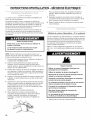
Risque d'explosion
Garder les matieres et les vapeurs inflammables, telle
que I'essence, loin de la secheuse.
Ne pas installer dans un garage.
Le non-respect de ces instructions peut causer
un decks, une explosion ou un incendie.
Pour I'installation d'une s_cheuse _ gaz :
IMPORTANT : Respecter les dispositions de tousles codes et
reglements en vigueur.
[] Determiner les exigences des codes : Certains codes limitent
ou prohibent I'installation d'une secheuse dans un garage, un
placard, une chambre &coucher. Consulter I'inspecteur local
des b&timents.
15"
(38,1crn)*
f
0"(ocrn)
14" m
(35,6 cm)
rnax.
Porte du
placard --_"
0" (0crn)
-
O" _ _
(0cm)
1" (2,5 cm)
Encastrement, vue avant Placard, vue laterale
On dolt pr_voir un espacement additionnel pour tenir cornpte _ventuellement
des moulures du mur, de la porte et du plancher, ou si le circuit d'_vacuation
comporte un coude.
20
La page charge ...
La page charge ...
La page charge ...
La page charge ...
La page charge ...
La page charge ...
La page charge ...
La page charge ...
La page charge ...
La page charge ...
La page charge ...
La page charge ...
La page charge ...
La page charge ...
La page charge ...
La page charge ...
-
 1
1
-
 2
2
-
 3
3
-
 4
4
-
 5
5
-
 6
6
-
 7
7
-
 8
8
-
 9
9
-
 10
10
-
 11
11
-
 12
12
-
 13
13
-
 14
14
-
 15
15
-
 16
16
-
 17
17
-
 18
18
-
 19
19
-
 20
20
-
 21
21
-
 22
22
-
 23
23
-
 24
24
-
 25
25
-
 26
26
-
 27
27
-
 28
28
-
 29
29
-
 30
30
-
 31
31
-
 32
32
-
 33
33
-
 34
34
-
 35
35
-
 36
36


Maytag MDG17CSAWW - 7.4 cu. Ft. Commercial Gas Dryer Installation Instructions Manual
- Catégorie
- Sèche-linge électriques
- Taper
- Installation Instructions Manual
dans d''autres langues
Documents connexes
Autres documents
-
Whirlpool CGM2761TQ0 Manuel utilisateur
-
-
-
White-Westinghouse CDG2000FW0 Guide d'installation
-
KitchenAid KHGV01RSS0 Le manuel du propriétaire
-
-
-
-
Kenmore 41771722511 Guide d'installation