Whirlpool WGD9400ST0 Le manuel du propriétaire
- Catégorie
- Sèche-linge
- Taper
- Le manuel du propriétaire
Ce manuel convient également à

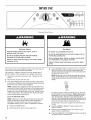
ELECTRONIC
GASDRYER
In the U.S.A., for questions about features, operation/performance,
parts, accessories or service call:
1-800-253-1301
In Canada, for assistance, installation and service call: 1-800-807-6777
or visit our website at.,. www,whirlpool,com or www,whirlpool,ca
SECHEUSEAGAZ
ELECTRONIQUE
Pour assistance, installation ou service composez le :
1-800-807-6777
ou visitez notre site web L_,,.
www,whirlpool,oa
Table of Contents/Table des mati_res ......................... 2
W10110851A

TABLEOFCONTENTS
RYER SAFETY ................................................................................ 3
INSTALLATION INSTRUCTIONS .................................................. 5
Tools and Parts ............................................................................ 5
Options ......................................................................................... 5
Location Requirements ............................................................... 6
Electrical Requirements ............................................................... 8
Gas Supply Requirements ........................................................... 8
Venting Requirements .................................................................. 9
Plan Vent System ....................................................................... 11
Install Vent System ..................................................................... 12
Install Leveling Legs ................................................................... 12
Level Dryer ................................................................................. 12
Make Gas Connection ............................................................... 13
Connect Vent .............................................................................. 13
Complete Installation ................................................................. 13
DRYER USE .................................................................................. 14
Starting Your Dryer ..................................................................... 14
Stopping Your Dryer .................................................................. 15
Pausing or Restarting ................................................................. 15
Control Locked ........................................................................... 15
Drying and Cycle Tips ................................................................ 15
Status Lights .............................................................................. 16
Cycles ......................................................................................... 16
Additional Features .................................................................... 17
Changing Cycles, Options and Modifiers .................................. 18
Drying Rack Option .................................................................... 18
DRYER CARE .............................................................................. 19
Cleaning the Dryer Location ...................................................... 19
Cleaning the Lint Screen ............................................................ 19
Cleaning the Dryer Interior ......................................................... 20
Removing Accumulated Lint ...................................................... 20
Vacation and Moving Care ......................................................... 20
Changing the Drum Light ........................................................... 20
TROUBLESHOOTING .................................................................. 21
Dryer Operation .......................................................................... 21
Dryer Results .............................................................................. 21
ASSISTANCE OR SERVICE ......................................................... 23
WARRANTY .................................................................................. 24
TABLEDESMATIERES
SECURITI :!:DE LA SECHEUSE .................................................... 25
INSTRUCTIONS D'INSTALLATION ............................................. 26
Outillage et pieces ...................................................................... 26
Options ....................................................................................... 27
Exigences d'emplacement ......................................................... 28
Specifications electriques .......................................................... 30
Alimentation en gaz .................................................................... 30
Exigences concernant I'evacuation ........................................... 32
Planification du systeme d'evacuation ...................................... 33
Installation du systeme d'evacuation ......................................... 35
Installation des pieds de nivellement ......................................... 35
Mise h niveau de la secheuse .................................................... 35
Raccordement au gaz ................................................................ 35
Raccordement du conduit d'evacuation ................................... 36
Achever I'installation .................................................................. 36
UTILISATION DE LA SI:!:CHEUSE................................................ 37
Mise en marche de la secheuse ................................................ 37
ArrGt de la secheuse ................................................................... 38
Pause ou remise en marche ....................................................... 38
Control Locked (verrouillage des commandes) ......................... 39
Conseils pour le sechage et les programmes ........................... 39
Temoins lumineux ...................................................................... 39
Programmes ............................................................................... 40
Caracteristiques supplementaires ............................................. 41
Changement des programmes, options et modificateurs .........42
Option de grille de sechage ....................................................... 42
ENTRETIEN DE LA SI_CHEUSE ................................................. 43
Nettoyage de I'emplacement dela secheuse ............................ 43
Nettoyage du filtre a charpie ...................................................... 43
Nettoyage de I'interieur de la secheuse ..................................... 44
Retrait de la charpie accumulee ................................................ 44
Precautions a prendre pour les vacances et
avant un demenagement ........................................................... 44
Changement de I'ampoule d'eclairage du tambour .................. 44
DI!:PANNAGE ................................................................................. 45
Fonctionnement de la secheuse ................................................ 45
Resultats de la secheuse ........................................................... 45
ASSISTANCE OU SERVICE ......................................................... 47
GARANTI E ..................................................................................... 48

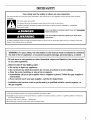
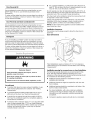
DRYERSAFETY
Your safety and the safety of others are very important.
We have provided many important safety messages in this manual and on your appliance. Always read and obey all safety
messages.
This is the safety alert symbol.
This symbol alerts you to potential hazards that can kill or hurt you and others.
All safety messages will follow the safety alert symbol and either the word "DANGER" or "WARNING."
These words mean:
You can be killed or seriously injured if you don't immediately
follow instructions.
You can be killed or seriously injured if you don't follow
instructions.
All safety messages will tell you what the potential hazard is, tell you how to reduce the chance of injury, and tell you what can
happen if the instructions are not followed.
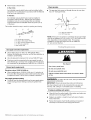
i WARNING: For your safety, the information in this manual must be followed to minimize
the risk of fire or explosion, or to prevent property damage, personal injury, or death.
- Do not store or use gasoline or other flammable vapors and liquids in the vicinity of this
or any other appliance.
- WHAT TO DO IF YOU SMELL GAS:
• Do not try to light any appliance.
• Do not touch any electrical switch; do not use any phone in your building.
• Clear the room, building, or area of all occupants.
• Immediately call your gas supplier from a neighbor's phone. Follow the gas supplier's
instructions.
• If you cannot reach your gas supplier, call the fire department.
- Installation and service must be performed by a qualified installer, service agency, or
the gas supplier.
In the State of Massachusetts, the following installation instructions apply:
[] Installations and repairs must be performed by a qualified or licensed contractor, plumber, or gasfitter qualified or licensed by
the State of Massachusetts.
[] If using a ball valve, it shall be a T-handle type.
[] A flexible gas connector, when used, must not exceed 3 feet.

IMPORTANT SAFETY INSTRUCTIONS
WARNING: To reduce the risk of fire, electric shock, or injury to persons when using the dryer, follow basic precautions,
including the following:
[] Read all instructions before using the dryer.
[] Do not place items exposed to cooking oils in your dryer.
Items contaminated with cooking oils may contribute to
a chemical reaction that could cause a load to catch fire.
[] Do not dry articles that have been previously cleaned in,
washed in, soaked in, or spotted with gasoline, dry-
cleaning solvents, or other flammable or explosive
substances as they give off vapors that could ignite or
explode.
[] Do not allow children to play on or in the dryer. Close
supervision of children is necessary when the dryer is
used near children.
[] Before the dryer is removed from service or discarded,
remove the door to the drying compartment.
[] Do not reach into the dryer if the drum is moving.
[] Do not install or store the dryer where it will be exposed
to the weather.
[] Do not tamper with controls.
[] Do not repair or replace any part of the dryer or attempt
any servicing unless specifically recommended in this
Use and Care Guide or in published user-repair
instructions that you understand and have the skills to
carry out.
[] Do not use fabric softeners or products to eliminate static
unless recommended by the manufacturer of the fabric
softener or product.
[] Do not use heat to dry articles containing foam rubber or
similarly textured rubber-like materials.
[] Clean lint screen before or after each load.
[] Keep area around the exhaust opening and adjacent
surrounding areas free from the accumulation of lint, dust,
and dirt.
[] The interior of the dryer and exhaust vent should be
cleaned periodically by qualified service personnel.
[] See installation instructions for grounding requirements.
SAVE THESE INSTRUCTIONS
IMPORTANT: The gas installation must conform with local codes, or in the absence of local codes, with the National Fuel Gas
Code, ANSi Z223.1/NFPA 54 or the Canadian Natural Gas and Propane installation Code, CSA B149.1.
The dryer must be electrically grounded in accordance with local codes, or in the absence of local codes, with the National
Electrical Code, ANSI/NFPA 70 or Canadian Electrical Code, CSA C22.1.

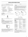
INSTALLATIONINSTRUCTIONS
Gather the required tools and parts before starting installation.
Read and follow the instructions provided with any tools listed
here.
8" or 10" pipe wrench
8" or 10" adjustable
wrench (for gas
connections)
Flat-blade screwdriver
Adjustable wrench that
opens to 1" (2.5 cm) or
hex-head socket wrench
(for adjusting dryer feet)
v4" nut driver or socket
wrench
• Level
• Knife
• Vent clamps
• Pipe-joint compound
resistant to LP gas
• Caulking gun and
compound (for installing
new exhaust vent)
• Pliers
• Tape measure
Parts supplied
Remove parts packages from dryer drum. Check that all parts are
included.
• Parts package
4 Leveling legs
NOTE: Do not use leveling legs if installing the dryer on a
pedestal.
Parts needed
Check local codes and with gas supplier. Check existing gas
supply, electrical supply and venting. Read "Electrical
Requirements," "Gas Supply Requirements" and "Venting
Requirements" before purchasing parts.
• For close-clearance installations between 31.5" (80.01 cm)
and 37" (93.98 cm), see "Plan Vent System" section for
venting requirements.
I_- 37" --_1
(93.98 cm)
Mobile home installations require special parts (listed following)
that may be ordered by calling the dealer from whom you
purchased your dryer. For further information, please refer to the
"Assistance or Service" section of this manual.
• Mobile Home Installation Kit. Ask for Part Number 346764.
• Metal exhaust system hardware.
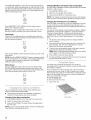
Pedestal
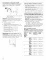
Are you placing the dryer on a pedestal? You have the option of
purchasing pedestals of different heights separately for this dryer.
You may select a 10" (25.4 cm) or 15.5" (39.4 cm) pedestal.
These pedestals will add to the total height of the dryer for a total
height of approximately 48" (121.9 cm) or 53.5" (135.9 cm),
respectively.
For a garage installation, you will need to place the 10" (25.4 cm)
pedestal at least 9" (22.9 cm) above the floor and the
15.5" (39.4 cm) pedestal at least 3.5" (8.9 cm) above the floor.
A B
A. 10" (25.4 cm) pedestal
B. 15.5" (39.4 cm) pedestal
The pedestals are available in several colors.
To order, call the dealer from whom you purchased your dryer or
refer to the "Assistance or Service" section of this manual.
Pedestal Color Part Number
Height
10" (25.4 cm) White WHP1000SC
10" (25.4 cm) Biscuit WHP1000ST
10" (25.4 cm) Diamond Dust WHP1000SU
(Silver)
10" (25.4 cm) Black Diamond WHP1000SB
15.5" (39.4 cm) White WHP1500SC
15.5" (39.4 cm) Biscuit WHP1500ST
15.5" (39.4 cm) Diamond Dust WHP1500SU
(Silver)
15.5" (39.4 cm) Black Diamond WHP1500SB
Stack Kit
Are you planning to stack your DUET_ washer and dryer? To do
so, you will need to purchase a Stack Kit.
To order, call the dealer from whom you purchased your dryer or
refer to the "Assistance or Service" section of this manual. Ask
for Part Number 8541503.

Door Reversal Kit
Are you planning to reverse the door swing direction on your
DUET®dryer? To do so, you will need to purchase a Door
Reversal Kit.
To order, call the dealer from whom you purchased your dryer or
refer to the "Assistance or Service" section of this manual. Ask
for Part Number 8579666.
Door Reversal and Stack Combination Kit
Are you planning to reverse the door swing direction on your
DUET®dryer and stack your DUET®washer and dryer? To do so,
you can purchase a Door Reversal and Stack Combination Kit.
To order, call the dealer from whom you purchased your dryer or
refer to the "Assistance or Service" section of this manual. Ask
for Part Number W10110889.
Backguard
If you are installing your DUET° washer and dryer and wish to
avoid having loose items fall behind your machines, you may
purchase a pair of washer/dryer backguards. These will reduce
the chance of items falling behind the machines during operation.
To order, call the dealer from whom you purchased your dryer or
refer to the "Assistance or Service" section of this manual. Ask
for Part Number 8558694 (White).
• For a garage installation, you will need to place the dryer at
least 18" (46 cm) above the floor. If using a pedestal, you will
need 18" (46 cm) to the bottom of the dryer.
Do not operate your dryer at temperatures below 45°F (7°C). At
lower temperatures, the dryer might not shut off at the end of an
automatic cycle. This can result in longer drying times.
The dryer must not be installed or stored in an area where it will
be exposed to water and/or weather.
Check code requirements. Some codes limit, or do not permit,
installation of the dryer in garages, closets, mobile homes or
sleeping quarters. Contact your local building inspector.
NOTE: No other fuel-burning appliance can be installed in the
same closet as a dryer.
Installation clearances
The location must be large enough to allow the dryer door to
open fully.
Dryer Dimensions
(130.81 cm)
38 ,,I
(96.52 cm)
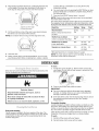
Explosion Hazard
Keep flammable materials and vapors, such as
gasoline, away from dryer,
Place dryer at least 18 inches (46 cm) above the floor
for a garage installation.
Failure to do so can result in death, explosion, or fire.
You will need
• A location that allows for proper exhaust installation. A gas
dryer must be exhausted to the outdoors. See "Venting
Requirements."
A grounded electrical outlet located within 2 ft (61 cm) of
either side of the dryer. See "Electrical Requirements."
A sturdy floor to support the total dryer weight of 200 Ibs
(90.7 kg). The combined weight of a companion appliance
should also be considered.
A level floor with a maximum slope of 1" (2.5 cm) under entire
dryer. If slope is greater than 1" (2.5 cm), install Extended
Dryer Feet Kit, Part Number 279810. Clothes may not tumble
properly, and automatic sensor cycles may not operate
correctly if dryer is not level.
'311/_''
{80 cm) 27"
"_/ _ (68.6crn)
*Most installations require a minimum 5" (12,7 cm) clearance
behind the dryer for the exhaust vent with elbow. See "Venting
Requirements."
Installation spacing for recessed area or closet installation
The following spacing dimensions are recommended for this
dryer. This dryer has been tested for spacing of 0" (0 cm)
clearance on the sides and rear. Recommended spacing should
be considered for the following reasons:
• Additional spacing should be considered for ease of
installation and servicing.
• Additional clearances might be required for wall, door and
floor moldings.
• Additional spacing should be considered on all sides of the
dryer to reduce noise transfer.
For closet installation, with a door, minimum ventilation
openings in the top and bottom of the door are required.
Louvered doors with equivalent ventilation openings are
acceptable.
• Companion appliance spacing should also be considered.

Custom undercounter installation - Dryer only
1"* _ _-_27"--}_ _ 1"*
2,5 cm) 68,6 cm 2.5 cm
*Required spacing
Closet installation - Dryer only
I1"*_ 31v2"_h"-I
(2.5cm) (80cm) (12.7cm)
A
A. Side view - closet or confined area
B. Closet door with vents
3"*
(7,6cm)
f
(7.6cm)
T
*Required spacing
**For side or bottom venting, O" (Ocm) spacing is allowed.
Recessed or closet installation - Dryer on pedestal
1..1I_- 31v_"-_15""1
1"-_ 1"_27"--_11<-1"
(2.5 cm) (68.6 cm) (2.5 cm) (2.5 cm) (80 cm) (12.7 cm)
A B
A.Recessedarea
B.Side view - closet or confined area
*Required spacing
**For side or bottom venting, 0" (0 cm) spacing is allowed.
Recommended installation spacing for cabinet
installation
• For cabinet installation, with a door,minimum ventilation
openings inthe top of the cabinet are required.
T'* (17.8cm)
T'* (17.8 crn)
5"** 31W' 1"* 1" 27" 1"
(12.7 cm) (80.0 cra) (2.5 cra)(2.5 cm)(68.6 cm) (2.5 cra)
I/ ;;.80ml
*Required spacing
**For side or bottom venting, O" (Ocm) spacing is allowed.
Recommended installation spacing for recessed or
closet installation, with stacked washer and dryer
The dimensions shown are for the recommended spacing.
48 in.2 *
(310crn2)
o
24 in? *
(155crn2)
•Required spacing
n
(12.7crn)
3"* (7.6 cm) .....................
2L
3"* (7.6 cm) =
_ -_- 1"* (2.5crn)
6"*Zcrn)
76"
{193 cm)
_- (2.51cm)
w'f_\X
_--27"_,, _ _ I"
68.6 cm 2.5 cm
*Required spacing

Mobile home - Additional installation requirements
This dryer is suitable for mobile home installations. The
installation must conform to the Manufactured Home
Construction and Safety Standard, Title 24 CFR, Part 3280
(formerly the Federal Standard for Mobile Home Construction
and Safety, Title 24, HUD Part 280) or Standard CAN/CSA-Z240
MH.
Mobile home installations require:
• Metal exhaust system hardware, which is available for
purchase from your dealer.
• Mobile Home Installation Kit Part Number 346764. See "Tools
and Parts" section for ordering information.
Special provisions must be made in mobile homes to
introduce outside air into the dryer. The opening (such as a
nearby window) should be at least twice as large as the dryer
exhaust opening.
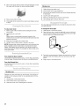
Electrical Shock Hazard
Plug into a grounded 3 prong outlet.
Do not remove ground prong.
Do not use an adapter.
Do not use an extension cord.
Failure to follow these instructions can result in death,
fire, or electrical shock.
120 Volt, 60 Hz., AC only, 15- or 20-amp fused electrical
supply is required. A time-delay fuse or circuit breaker is
recommended. It is also recommended that a separate circuit
serving only this dryer be provided.
GROUNDING INSTRUCTIONS
• For a grounded, cord-connected dryer:
This dryer must be grounded. In the event of malfunction or
breakdown, grounding will reduce the risk of electric shock
by providing a path of least resistance for electric current.
This dryer is equipped with a cord having an equipment-
grounding conductor and a grounding plug. The plug must
be plugged into an appropriate outlet that is properly
installed and grounded in accordance with all local codes
and ordinances.
WARNING: Improper connection of the equipment-
grounding conductor can result in a risk of electric shock.
Check with a qualified electrician or service representative
or personnel if you are in doubt as to whether the dryer is
properly grounded. Do not modify the plug provided with the
dryer: if it will not fit the outlet, have a proper outlet installed
by a qualified electrician.
SAVE THESE INSTRUCTIONS
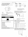
Explosion Hazard
Use a new CSA international approved gas supply line.
install a shut=off valve.
Securely tighten all gas connections.
If connected to LP, have a qualified person make sure
gas pressure does not exceed 13" (33 cm) water
column.
Examples of a qualified person include:
licensed heating personnel,
authorized gas company personnel, and
authorized service personnel.
Failure to do so can result in death, explosion, or fire.
Gas Type
Natural gas:
This dryer is equipped for use with Natural gas. It is design-
certified by CSA International for LP (propane or butane) gases
with appropriate conversion.
• Your dryer must have the correct burner for the type of gas in
your home. Burner information is located on the rating plate
in the door well of your dryer. If this information does not
agree with the type of gas available, contact your dealer or
call the phone numbers referenced in the "Assistance or
Service" section of this manual.
LP gas conversion:
Conversion must be made by a qualified technician.
No attempt shall be made to convert the appliance from the gas
specified on the model/serial rating plate for use with a different
gas without consulting your gas company.
Gas supply line
• Must include 1/8"NPT minimum plugged tapping accessible
for test gauge connection, immediately upstream of the gas
connection to the dryer. See illustration.
1/2"IPS pipe is recommended.
%" approved aluminum or copper tubing is acceptable for
lengths under 20 ft (6.1 m) if local codes and gas supplier
permit.
If you are using Natural gas, do not use copper tubing.
Lengths over 20 ft (6.1 m) should use larger tubing and a
different size adapter fitting.
If your dryer has been converted to use LP gas, %" LP
compatible copper tubing can be used. If the total length of
the supply line is more than 20 ft (6.1 m), use larger pipe.
NOTE: Pipe-joint compounds that resist the action of LP gas
must be used. Do not use TEFLON _ttape.

• Must include a shutoff valve:
In the U.S.A.:
An individual manual shutoff valve must be installed within
six (6)feet (1.8 m) of the dryer in accordance with the National
Fuel Gas Code, ANSI Z223.1.
In Canada:
An individual manual shutoff valve must be installed in
accordance with the B149.1, Natural Gas and Propane
Installation Code. It is recommended that an individual
manual shutoff valve be installed within six (6) feet (1.8 m)
of the dryer.
The location should be easy to reach for opening and closing.
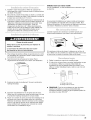
A C E
B D
A. %" flexible gas connector
B. %" pipe to flare adapter fitting
C. Vs"NPT minimum plugged tapping
D. Y/' NPT gas supply line
E. Gas shutoff valve
Gas supply connection requirements
• Use an elbow and a 3/8"flare x %" NPT adapter fitting
between the flexible gas connector and the dryer gas pipe, as
needed to avoid kinking.
• Use only pipe-joint compound. Do not use TEFLON _ tape.
• This dryer must be connected to the gas supply line with a
listed flexible gas connector that complies with the standard
for connectors for gas appliances, ANSI Z21.24 or CSA 6.10.
Burner input requirements
Elevations above 10,000 ft (3,048 m):
• When installed above 10,000 ft (3,048 m) a 4% reduction of
the burner Btu rating shown on the model/serial number plate
is required for each 1,000 ft (305 m) increase in elevation.
Gas supply pressure testing
• The dryer must be disconnected from the gas supply piping
system during pressure testing at pressures greater than
1/2psi.
Dryer gas pipe
• The gas pipe that comes out through the rear of your dryer
has a %" male pipe thread.
1½"
A (3.8cm)
A. Y2"NPT gas supply line
B. _" NPT dryer pipe
*NOTE: Ifthe dryer is mounted on a pedestal, the gas pipe height
must be an additional 10" (25.4 cm) or 15.5" (39.4 cm) from the
floor, depending on the pedestal model. For a garage
installation, the gas pipe height must be an additional
18" (46 cm) from the floor.
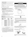
Fire Hazard
Use a heavy metal vent.
Do not use a plastic vent.
Do not use a metal foil vent.
Failure to follow these instructions can result in death
or fire.
WARNING: To reduce the risk of fire, this dryer MUST BE
EXHAUSTED OUTDOORS.
IMPORTANT: Observe all governing codes and ordinances.
The dryer exhaust must not be connected into any gas vent,
chimney, wall, ceiling or a concealed space of a building.
If using an existing vent system
• Clean lint from the entire length of the system and make sure
exhaust hood is not plugged with lint.
• Replace any plastic or metal foil vent with rigid or flexible
heavy metal vent.
• Review Vent system chart. Modify existing vent system if
necessary to achieve the best drying performance.
1-®TEFLON is a registered trademark of E.I. Du Pont De Nemours and Company.

If this is a new vent system
Vent material
• Use a heavy metal vent. Do not use plastic or metal foil vent.
• 4" (10.2 cm) heavy metal exhaust vent and clamps must be
used. DURASAFE TM venting products are recommended.
Exhaust
4" (10.2cm) heavymetal exhaust vent
DURASAFE TM vent products can be purchased from your
dealer or by calling Whirlpool Parts and Accessories. For
more information, see the "Assistance or Service" section of
this manual.
Rigid metal vent
• For best drying performance, rigid metal vents are
recommended.
• Rigid metal vent is recommended to avoid crushing and
kinking.
Flexible metal vent
• Flexible metal vents are acceptable only if accessible for
cleaning.
• Flexible metal vent must be fully extended and supported
when the dryer is in its final location.
• Remove excess flexible metal vent to avoid sagging and
kinking that may result in reduced airflow and poor
performance.
• Do not install flexible metal vent in enclosed walls, ceilings or
floors. •
Elbows
45° elbows provide better airflow than 90° elbows.
Good Better
Clamps
• Use clamps to seal all joints.
• Exhaust vent must not be connected or secured with screws
or other fastening devices that extend into the interior of the
duct. Do not use duct tape.
Clamp
Recommended hood styles are shown here.
_ (1J._"!rn)
(10.2 cm)
A. Louvered hood style
B.Box hood style
The angled hood style (shown here) is acceptable.
" _ 21/2 .'
(6.4 cm)
An exhaust hood should cap the vent to keep rodents and
insects from entering the home.
Exhaust hood must be at least 12" (30.5 cm) from the ground
or any object that may be in the path of the exhaust (such as
flowers, rocks or bushes, snow line, etc.).
Do not use an exhaust hood with a magnetic latch.
improper venting can cause moisture and lint to collect
indoors, which may result in:
[] Moisture damage to woodwork, furniture, paint, wallpaper,
carpets, etc.
[] Housecleaning problems and health problems.
10

Choose your exhaust installation type
Recommended exhaust installations
Typical installations vent the dryer from the rear of the dryer.
Other installations are possible.
B
A=--
............... F
...................................G
A
A. Standard rear offset exhaust installation
B. Left or right side exhaust installation
C. Bottom exhaust installation (not an option
with pedestal installations)
A. Dryer
B. Elbow
C. Wall
D. Exhaust hood
E. Clamps
F. Rigid metal or flexible metal vent
G. Vent length necessary to connect elbows
H. Exhaust outlet
Optional exhaust installations
This dryer can be converted to exhaust out the right side, left
side, or through the bottom. Contact your local dealer to have the
dryer converted.
Fire Hazard
Cover unused exhaust holes with one of the
following kits:
279818 (white)
279820 (black)
279925 (biscuit)
279989 (pewter)
280171 (diamond dust)
Contact your local dealer.
Failure to follow these instructions can result in death,
fire, electrical shock, or serious injury.
Alternate installations for close clearances
Venting systems come in many varieties. Select the type best for
your installation. Two close-clearance installations are shown.
Refer to the manufacturer's instructions.
) ,,,
\\,\ II \\, j
A B
A. Over-the-top installation (also available with one
offset elbow)
B. Periscope installation
NOTE: The following kits for close clearance alternate
installations are available for purchase. Please see the
"Assistance or Service" section of this manual to order.
• Over-the-Top Installation:
Part Number 4396028
• Periscope Installation For use with dryer vent to wall vent
mismatch):
Part Number 4396037 - 0" (0 cm) to 18" (45.72 cm)
mismatch
Part Number 4396011 - 18" (45.72 cm) to 29" (73.66 cm)
mismatch
Part Number 4396014 - 29" (73.66 cm) to 50" (127 cm)
mismatch
Special provisions for mobile home installations
The exhaust vent must be securely fastened to a noncombustible
portion of the mobile home structure and must not terminate
beneath the mobile home. Terminate the exhaust vent outside.
11

Determine vent path
• Select the route that will provide the straightest and most
direct path outdoors.
• Plan the installation to use the fewest number of elbows and
turns.
• When using elbows or making turns, allow as much room as
possible.
• Bend vent gradually to avoid kinking.
• Use the fewest 90 °turns possible.
Determine vent length and elbows needed for best
drying performance
• Use the following Vent system chart to determine type of vent
material and hood combinations acceptable to use.
NOTE: Do not use vent runs longer than those specified in
the Vent system chart. Exhaust systems longer than those
specified will:
• Shorten the life of the dryer.
• Reduce performance, resulting in longer drying times and
increased energy usage.
The Vent system chart provides venting requirements that will
help to achieve the best drying performance.
Vent system chart
NOTE: Side and bottom exhaust installations have a 90° turn
inside the dryer. To determine maximum exhaust length, add one
90° turn to the chart.
Number of Type of Box or Angled
90° turns vent Iouvered hoods
or elbows hoods
0 Rigid metal 64 ft (20 m) 58 ft (17.7 m)
Flexible metal 36 ft (11 m) 28 ft (8.5 m)
1 Rigid metal 54 ft (16.5 m) 48 ft (14.6 m)
Flexible metal 31 ft (9.4 m) 23 ft (7 m)
2 Rigid metal 44 ft (13.4 m) 38 ft (11.6 m)
Flexible metal 27 ft (8.2 m) 19 ft (5.8 m)
3 Rigid metal 35 ft (10.7 m) 29 ft (8.8 m)
Flexible metal 25 ft (7.6 m) 17 ft (5.2 m)
4 Rigid metal 27 ft (8.2 m) 21 ft (6.4 m)
Flexible metal 23 ft (7 m) 15 ft (4.6 m)
1. Install exhaust hood. Use caulking compound to seal exterior
wall opening around exhaust hood.
2. Connect vent to exhaust hood. Vent must fit inside exhaust
hood. Secure vent to exhaust hood with 4" (10.2 cm) clamp.
3. Run vent to dryer location. Use the straightest path possible.
See "Determine vent path" in "Plan Vent System." Avoid 90°
turns. Use clamps to seal all joints. Do not use duct tape,
screws or other fastening devices that extend into the interior
of the vent to secure vent.
Excessive Weight Hazard
Use two or more people to move and install dryer.
Failure to do so can result in back or other injury.
1. To protect the floor, use a large flat piece of cardboard from
the dryer carton. Place cardboard under the entire back edge
of the dryer.
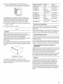
2. Firmly grasp the body of the dryer. Gently lay the dryer on the
cardboard. See illustration.
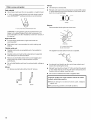
3. Examine the leveling legs. Find the diamond marking.
4. Screw the legs into the leg holes by hand. Use a wrench to
finish turning the legs until the diamond marking is no longer
visible.
5. Place a carton corner post from dryer packaging under each
of the 2 dryer back corners. Stand the dryer up. Slide the
dryer on the corner posts until it is close to its final location.
Leave enough room to connect the exhaust vent or gas line.
For mobile home use
Gas dryers must be securely fastened to the floor at the time of
installation.
Mobile home installations require a Mobile Home Installation Kit.
For more information, please reference the service numbers in
the "Assistance or Service" section of this manual.
Check the levelness of the dryer. Check levelness first
side to side, then front to back.
If the dryer is not level, prop up the dryer using a wood block.
Use a wrench to adjust the legs up or down and check again for
levelness.
12

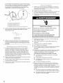
1.
2.
3.
4.
_yp _. "! '! _
Remove the red cap from the gas pipe.
Using a wrench to tighten, connect the gas supply to the
dryer. Use pipe-joint compound on the threads of all non-
flared male fittings. If flexible metal tubing is used, be sure
there are no kinks.
A............................._ _ ............................B
A. Flared male fitting
B. Non-flared male fitting
NOTE: For LP gas connections, you must use pipe-joint
compound resistant to the action of LP gas. Do not use
TEFLON °t tape.
A combination of pipe fittings must be used to connect the
dryer to the existing gas line. Shown is a recommended
connection. Your connection may be different, according to
the supply line type, size and location.
!
A. _" flexible gas connector
B. _" dryerpipe
C. _" to _" pipe elbow
D. _" pipe-to-flare adapter fitting
\
C
Open the shutoff valve in the supply line. The valve is open
when the handle is parallel to the gas pipe.
A. Closed valve
B.Open valve
Test all connections by brushing on an approved
noncorrosive leak-detection solution. Bubbles will show a
leak. Correct any leak found.
S'iSl a_.
: e
1. Check that a[[ parts are now installed. If there is an extra part,
go back through the steps to see which step was skipped.
2. Check that you have all of your tools.
3. Check the dryer's final location. Be sure the vent is not
crushed or kinked.
4. Check that the dryer is level. See "Level Dryer."
5.
6.
7.
8.
9.
10.
11.
Electrical Shock Hazard
Plug into a grounded 3 prong outlet.
Do not remove ground prong.
Do not use an adapter.
Do not use an extension cord,
Failure to follow these instructions can result in death,
fire, or electrical shock.
Plug into a grounded 3 prong outlet. Turn on power.
Remove any protective film or tape remaining on the dryer.
Dispose of/recycle all packaging materials.
Read "Dryer Use."
Wipe the dryer drum interior thoroughly with a damp cloth to
remove any dust.
Select a Timed Dry heated cycle, and start the dryer. Do not
select the Air Only Temperature setting.
If the dryer will not start, check the following:
• Dryer is plugged into a grounded 3 prong outlet.
• Electrical supply is connected.
• Household fuse is intact and tight, or circuit breaker has
not tripped.
• Dryer door is closed.
When the dryer has been running for 5 minutes, open the
dryer door and feel for heat. Ifyou feel heat, cancel cycle and
close door. If you do not feel heat, turn off the dryer and
check that the gas supply line shutoff valve is open.
• Ifthe gas supply line shutoff valve is closed, open it, then
repeat the 5-minute test as outlined above.
• Ifthe gas supply line shutoff valve is open, contact a
qualified technician.
1. Using a 4" (10.2 cm) clamp, connect vent to exhaust outlet in
dryer. If connecting to existing vent, make sure the vent is
clean. The dryer vent must fit over the dryer exhaust outlet
and inside the exhaust hood. Check that the vent is secured
to exhaust hood with a 4" (10.2 cm) clamp.
2. Move dryer into its final location. Do not crush or kink vent.
3. (On gas models) Check that there are no kinks in the flexible
gas line.
4. Once the exhaust vent connection is made, remove the
corner posts and cardboard.
1-®TEFLON is a registered trademark of E.I. Du Pont De Nemours and Company.
13

DRYERUSE
Explosion Hazard
Keep flammable materials and vapors, such as
gasoline, away from dryer.
Do not dry anything that has ever had anything
flammable on it (even after washing).
Failure to follow these instructions can result in death,
explosion, or fire.
Fire Hazard
No washer can completely remove oil.
Do not dry anything that has ever had any type of oil on
it (including cooking oils),
items containing foam, rubber, or plastic must be dried
on a clothesline or by using an Air Cycle.
Failure to follow these instructions can result in death
or fire.
This manual covers several different models. Your dryer may not
have all of the cycles and features described.
The following is a guide to starting your dryer. Please refer to
specific sections of this manual for more detailed information.
f. Clean lint screen before each load. See "Cleaning the Lint
Screen."
2. Place laundry in dryer and shut door.
3. Press the POWER button then rotate the dial to select either
an Automatic or Manual Cycle. The preset settings and drying
time for the cycle chosen will be displayed.
NOTE: A default time is displayed when an Automatic Cycle
is selected. During the first few minutes of the drying process,
the cycle time may automatically vary from the default time
based on the size and fabric type of the load. Toward the end
of the drying process, the estimated time display will adjust
again, showing the final drying time.
To use an Automatic Cycle
NOTE: A light next to each feature will glow green when the
feature is selected or will glow amber when the feature is
selectable. The light will not glow when the selection is
unavailable with the cycle or option combinations selected.
• Press the POWER button.
• Rotate the dial to select an Automatic Cycle.
Select DRYNESS LEVEL to adjust how dry you want the
load to be. As the cycle runs, the control senses the
dryness of the load and adjusts the time automatically for
the selected Dryness Level.
NOTE: Most loads may be dried using Normal, which is
shown in bold letters on your control panel. Normal is the
energy preferred dryness level and will use the least
energy.
Mo_e
Non//a(
ess
The default dryness setting is Normal when an Auto Dry
Cycle is selected. You can select a different dryness level,
depending on your load, by pressing DRYNESS LEVEL
and choosing More, Normal or Less. Selecting More,
Normal or Less automatically adjusts the dryness level at
which the dryer will shut off. Once a dryness level is set, it
cannot be changed without stopping the cycle.
The Dryness Level can be changed only with Automatic
Cycles.
Press the WRINKLE SHIELD TM feature button if this
option is desired.
Press the CYCLE SIGNAL button to set end of cycle
signal volume to desired level.
Press the DAMP DRY CYCLE SIGNAL button to set damp
dry signal volume to desired level.
14

• Press and hold START button until dryer starts (about
1 second).
Once an Automatic cycle has started, the WRINKLE
SHIELD TM feature and cycle signals can be adjusted. Press
the PAUSE/CANCEL key twice to stop the dryer and clear the
settings, allowing you to select another cycle and Dryness
Level.
NOTE: Time and Temperature are not adjustable for
Automatic Cycles. Pressing the DRY TIME or TEMPERATURE
buttons will cause a triple beep, indicating that the time
cannot be changed.
How Automatic Cycles Work
The AccelerCare TM function improves drying performance
with Auto Moisture Sensing Plus, which advances the cycle
as moisture is extracted from clothing. A thermistor
(electronic temperature sensor) and moisture sensing strips in
the dryer drum help measure the amount of moisture in the
clothes as they tumble. An electronic control determines the
load type to help save time, avoid overdrying, and increase
the accuracy of the end dryness level. After the first 5 minutes
of an automatic cycle, the estimated time display will adjust
based on the approximate load size, cycle, dryness level
selected and amount of moisture left in the clothes. When the
clothes have reached approximately 80% of the dryness level
selected, the estimated time display will adjust again,
showing the final drying time. The AccelerCare TM feature
takes the guesswork out of drying time and enhances fabric
care.
To use a Manual Cycle
NOTE: A light next to each feature will glow green when the
feature is selected or will glow amber when the feature is
selectable. The light will not glow when the selection is
unavailable with the cycle or option combinations selected.
• Press POWER.
Rotate the dial to select a Manual Cycle.
Press the DRY TIME up or down buttons until the desired
drying time is displayed. Press DRY TIME, and the time
will change by 1-minute intervals. Press and hold DRY
TIME, and the time will change by 5-minute intervals. The
initial time displayed is the actual drying time.
Adi_stManual
0ryTime
®®
The Dry Time feature can be used only with Manual
Cycles.
Press TEMPERATURE until the desired temperature
glows green.
I High
Medium
Low
ExtraLow
Air Only
Temperature
Adjst Manual
Cyde_Only
Temperature settings can be changed only with Manual
Cycles.
Press the WRINKLE SHIELD TM feature button if this
option is desired.
Press the CYCLE SIGNAL button to set end of cycle
signal volume to desired level.
• Press and hold START button until dryer starts (about
1 second).
NOTE: Dryness Level is not adjustable for Manual Cycles.
Pressing the Dryness Level button will cause the triple beep
indicating that this option is not selectable.
While a Manual Cycle is running, you can change the settings
for Time, Temperature, the WRINKLE SHIELD TM feature and
the cycle signals. Press the PAUSE/CANCEL key twice to
stop the dryer and clear the settings, allowing you to select
another cycle.
To stop your dryer at anytime
Press PAUSE/CANCELtwice or open the door.
To pause the dryer at any time
Open the door or press PAUSE/CANCEL once.
To restart the dryer
Close the door and press and hold START button until dryer
starts.
NOTE: Drying will continue from where the cycle was interrupted,
if you close the door and press Start within 5 minutes. If the cycle
is interrupted for more than 5 minutes, the dryer will shut off.
Select new cycle settings before restarting the dryer.
This feature allows you to lock your settings to avoid unintended
use of the dryer. You can also use the Control Locked feature to
avoid unintended cycle or option changes during dryer operation.
To enable the Control Locked feature when dryer is
running:
Press and hold the CONTROL LOCK/UNLOCK button for
3 seconds. The control is locked when a single beep is heard and
the Control Locked status light is on.
• When the dryer is off, it is not necessary to press the Control
On button before activating the Control Locked feature.
To unlock:
Press and hold the CONTROL LOCK/UNLOCK button for
3 seconds to turn this feature off.
NOTE: When the dryer is running and Control Locked is on, the
dryer can be stopped by pressing the Pause/Cancel button, but
cannot be restarted until the control is unlocked.
Select the correct cycle and dryness level or temperature for your
load. If an Automatic Cycle is running, the display shows the
estimated cycle time when your dryer is automatically sensing
the dryness level of your load. If a Manual Cycle is running, the
display shows the exact number of minutes remaining in the
cycle.
Cool Down tumbles the load without heat during the last few
minutes of all cycles. Cool Down makes the loads easier to
handle and reduces wrinkling. The length of the Cool Down
depends on the load size and dryness level.
Drying tips
• Follow care label directions when they are available.
• If desired, add a fabric softener sheet. Follow package
instructions.
• Remove the load from the dryer as soon as tumbling stops to
reduce wrinkling. This is especially important for permanent
press, knits and synthetic fabrics.
15

Avoid drying heavy work clothes with lighter fabrics. This
could cause overdrying of lighter fabrics, leading to increased
shrinking or wrinkling.
If you dry sheets in a mixed load or large items in the Bulky
Items cycle, rearrange the load when the signal sounds. This
will aid in the drying process.
Indicator lights
Other indicator lights on the control panel show Cycle,
Temperature, Dryness Level, and cycle signal settings selected.
The time display will indicate the estimated or actual time
remaining in a cycle.
Cycle tips
• Dry most loads using the preset cycle settings.
• Refer to the Automatic or Manual Preset Cycle Settings chart
(in the "Cycles" section) for a guide to drying various loads.
Drying temperature and Dryness Level are preset when
you choose an Automatic Cycle. You can choose a
different dryness level, depending on your load by
pressing the DRYNESS LEVEL button to select MORE,
NORMAL or LESS.
• Ifyou wish to adjust the cycle length of a Manual Cycle,
you must press the DRY TIME up or down buttons. Adjust
the temperature of a Manual Cycle by pressing
TEMPERATURE until the desired temperature is selected.
NOTE: You cannot choose a Dryness Level with Manual
Cycles.
Select the drying cycle that matches the type of load you are
drying. See Automatic Preset or Manual Preset Cycle Settings
chart.
NORMAL
CASUAL BULKYITEMS
DELICATE HEAVYDUTY
SUPER
DELICATE
DAMPDRY
AUTOMATICCYCL[S [viANUALCYCLES
TIMEDDRY
TOUCHUP
_UICKDRY
You may follow the progress of your dryer with the drying Status
indicator lights.
WrinkleShield Sensing
Wet Damp C001D0wnDone
WRINKLE SHIELD TM Feature
The WRINKLE SHIELD TM feature light glows during the WRINKLE
SHIELD TM feature (when selected).
Sensing
When a cycle is first turned on, the Sensing light glows until a wet
item is detected.
• In an Automatic Cycle, if a wet item has not been detected
within 10 minutes, the Sensing light will turn off and the dryer
will shut down.
• In a Manual Cycle, if a wet item is not detected after
10 minutes, the Wet light turns on and the selected cycle
continues.
Cycle Control knob
Automatic Cycles
Automatic Cycles allow you to match the cycle to the load you
are drying. See the following Automatic Preset Cycle Settings
chart. Each cycle dries certain fabrics at the recommended
temperature. A sensor detects the moisture in the load and
automatically adjusts the drying time for optimal drying.
Heavy Duty
Use this cycle to get High heat for heavyweight mixed loads,
cotton towels or jeans.
Bulky Items
Use this cycle to get Medium heat for drying large items that
require very long drying times such as jackets, comforters and
pillows. Rearrange the load halfway through the dryer cycle. This
will aid in the drying process.
Normal
Use this cycle to get Medium heat for drying sturdy fabrics such
as work clothes and sheets.
Wet
The Wet light will turn on when a wet item has been detected in
the dryer. The Wet light will remain on until:
• The damp dry point is reached in an Automatic Cycle.
• The dryer enters the cool down period in a Manual Cycle.
Damp
The Damp light indicates that the load has reached the damp dry
level. To be alerted when your load is approximately 80% dry, you
may use the Damp Dry Cycle Signal option. See "Damp Dry
Cycle Signal" in "Additional Features" section.
NOTE: The Damp light is not used with manual cycles.
Cool Down
The Cool Down light glows during the cool down part of the
cycle. Laundry is cooling down for ease in handling.
Done
The Done light illuminates when the drying cycle is finished. This
indicator stays on during the WRINKLE SHIELD TM feature.
Casual
Use this cycle to get Low heat for drying no-iron fabrics such as
sport shirts, casual business clothes and permanent press
blends.
Delicate
Use this cycle to get Low heat to gently dry items such as
washable knit fabrics.
Super Delicate
Use this cycle to get Extra-Low heat to gently dry items such as
lingerie.
Damp Dry
Use this cycle to dry items to a damp level using Low heat. Damp
dry items such as jeans (to avoid stiffness) or cotton clothing (to
make ironing easier). The temperature setting on this cycle
cannot be adjusted. Items will have different levels of dampness.
At the end of this cycle, clothes will be damp. To be alerted when
this cycle is complete, select the End of Cycle Signal.
16

Automatic Preset Cycle Settings
Automatic Cycles Temperature Time*
Load Type (Minutes)
HEAVY DUTY High 50
Heavyweight items, towels, jeans
BULKY ITEMS Medium 55
Jackets, comforters, pillows
NORMAL Medium 40
Corduroys, work clothes, sheets
CASUAL Low 35
Permanent press, synthetics
DELICATE Low 30
Lingerie, blouses, washable
woolens
SUPER DELICATE Extra Low 25
Lingerie, blouses, washable
Woolens
DAMP DRY Low 20
Clothes to come out suitable for
ironing
*Estimated Time with Dryness Level (medium) setting. Time will
vary depending on load type and load size.
Manual Cycles
Use Manual Cycles to select a specific amount of drying time and
a drying temperature. When a Manual Cycle is selected, the
Estimated Time Remaining display shows the actual time
remaining in your cycle. You can change the actual time in the
cycle by pressing the DRY TIME up or down buttons.
Timed Dry
Use this cycle to complete drying if items are still damp after an
Automatic Cycle. Timed Dry is also useful for drying heavyweight
and bulky items such as bedspreads and work clothes.
Lightweight garments, such as exercise wear, can be dried using
Timed Dry on a Low temperature setting.
Touch Up
Use this setting to help smooth out wrinkles from such items as
clothes packed in a suitcase or wrinkled from being left in the
dryer too long.
Quick Dry
Use this cycle for drying small loads or loads that need a short
drying time.
Manual Preset Cycle Settings
Manual Cycles Temperature Default Time
Load Type (Minutes)
TIMED DRY High 40
Heavyweight items, bulky
items, bedspreads, work
clothes
TOUCH UP Medium 15
Helps to smooth out
wrinkles
QUICK DRY High 21
Small loads
Air Only
Use the Air Only setting for items that require drying without heat
such as rubber, plastic and heat-sensitive fabrics. This chart
shows examples of items that can be dried using Air Only.
Type of Load Time*
(Minutes)
Foam rubber - pillows, padded bras, stuffed toys 20 - 30
Plastic - Shower curtains, tablecloths 20 - 30
Rubber-backed rugs 40 - 50
Olefin, polypropylene, sheer nylon 10 - 20
*Reset time to complete drying, if needed.
When using Air Only
• Check that coverings are securely stitched.
• Shake and fluff pillows by hand periodically during the cycle.
• Dry item completely. Foam rubber pillows are slow to dry.
NOTE: Automatic Cycles are not available when using the Air
Only setting.
Drum Light
Select Drum Light to turn on the light inside the dryer drum.
During a cycle, if Drum Light is selected, the drum light turns on
and will remain on until DRUM LIGHT is pressed again, the door
is open and closed, or the door is left open for 20 minutes.
When the dryer is not running, the drum light will turn on when
DRUM LIGHT is pressed or the dryer door is opened, and it will
remain on until the dryer door has been open for 20 minutes, the
dryer door is closed or DRUM LIGHT is pressed again.
Press DRUM LIGHT at any time to turn the drum light ON or OFE
WRINKLE SHIELD TM Feature
When you are unable to remove a load of clothes from the dryer
as soon as it stops, wrinkles can form. The WRINKLE SHIELD TM
feature periodically tumbles, rearranges and fluffs the load to help
keep wrinkles from forming.
• Press the WRINKLE SHIELD TM feature to get up to
120 minutes of heat-free, periodic tumbling at the end of a
cycle.
• Stop at any time by pressing the WRINKLE SHIELD TM feature
or opening the dryer door.
For the Casual Cycle, the WRINKLE SHIELD TM feature is
preset to "ON." The other cycles will retain the WRINKLE
SHIELD TM feature setting. (For example, if you select the
WRINKLE SHIELD TM feature in the Normal cycle, the
WRINKLE SHIELD TM feature will be on the next time you
select the Normal cycle.)
NOTE: If you do not select the WRINKLE SHIELD TM feature, the
dryer stops after the cool down period.
Damp Dry Cycle Signal
On some models, the Damp Dry Signal may be selected to alert
you that your clothes are approximately 80% dry. This is useful
when you want to remove lightweight items in a mixed load to
avoid overdrying or remove partially dry items that may need
ironing.
17

The DAMP DRY SIGNAL is useful when drying bedsheets/linens
in a mixed load. When the signal goes off, open the door to stop
the dryer, rearrange the load inside the dryer, close the door and
restart the dryer to finish the drying cycle. Rearranging the load
will aid in the drying process.
[0_d
Soft
Off
Press DAMP DRY CYCLE SIGNAL until the desired volume
(Loud, Soft or Off) glows green.
NOTE: This signal is independent of the Damp Dry Cycle. The
Damp Dry Signal is available only with the Automatic Cycles.
Cycle Signal
The End of Cycle Signal produces an audible sound when the
drying cycle is finished. Promptly removing clothes at the end of
the cycle reduces wrinkling.
Loud
Soft
Off
Cycle
Signal
Press CYCLE SIGNAL until the desired volume (Loud, Soft or Off)
glows green.
NOTE: When the WRINKLE SHIELD TM feature is selected and the
End of Cycle Signal is on, an audible sound will be emitted every
5 minutes until the clothes are removed, or the WRINKLE
SHIELD TM feature is finished.
Button Sound
You can change the volume of the sound of the beeps. Press
BUTTON SOUND until the desired volume (Loud, Soft or Off)
glows green. The Power and Cancel buttons will still beep softly
even when the Button Sound volume is set to Off.
Loud
Soft
Off
Button
Sound
Changing Modifiers and Options after pressing Start
You can change a Modifier or Option anytime before the selected
Modifier or Option begins.
1. Press PAUSE/CANCEL once.
2. Select the new Modifier and/or Option.
3. Press and hold START to continue the cycle.
NOTE: If you happen to press Pause/Cancel twice, the program
clears and your dryer shuts down. Restart the selection process.
Changing the Preset Dryness Level Settings
If all your loads on all Auto Dry cycles are consistently not as dry
as you would like, you may change the preset Dryness Level
settings to increase the dryness. This change will affect all of your
Auto Dry cycles.
Your Dryness Level settings can be adjusted to adapt to different
installations, environmental conditions or personal preference.
There are 3 drying settings: 1 (factory preset dryness level),
2 (slightly dryer clothes, approximately 15% more drying time)
and 3 (much dryer clothes, approximately 30% more drying
time).
1. The Dryness Level settings cannot be changed while the
dryer is running.
2. Press and hold the Dryness Level button for 5 seconds. The
dryer will beep, and "CF" will be displayed for 1 second
followed by the current drying setting.
3. To select a new drying setting, press the Dryness Level key
again until the desired drying setting is shown.
NOTE: While cycling through the settings, the current setting
will not flash, but the other settings will flash.
4. Press START to save the drying setting.
5. The drying setting you selected will become your new preset
drying setting for all Auto Dry cycles.
The drying rack is useful for drying items you would not
necessarily want to tumble dry or that you would normally line dry
(for example, sweaters).
If your model does not have a drying rack, you may be able to
purchase one for your model. To find out whether your model
allows drying rack usage and for information on ordering, please
refer to the front page of the manual or contact the dealer from
whom you purchased your dryer.
To use the drying rack
Do not remove the lint screen.
1. Open dryer door.
You can change Auto Cycles, Timed Cycles, Modifiers and
Options anytime before pressing Start.
• Three short tones sound if an unavailable combination is
selected. The last selection will not be accepted.
Changing Cycles after pressing Start
1. Press PAUSE/CANCEL twice. This ends the current cycle.
2. Select the desired cycle and options.
3. Press and hold START.The dryer starts at the beginning of
the new cycle.
NOTE: If you do not press Start within 5 minutes of selecting the
cycle, the dryer automatically shuts off.
A. Front edge
18

2.
Place drying rack inside dryer drum, positioning the back wire
on the ledge of the inner dryer back panel. Push down on
front edge of drying rack to secure over the lint screen.
A. Dryerrack front edge
B.Dryerback panel
3. Put the wet items on top of the rack. Leave space between
the items so air can reach all the surfaces.
NOTE: Do not allow items to hang over the edge of the rack.
4.
5.
Close the door.
Select a timed drying cycle and temperature, or an air cycle
(see following chart). Items containing foam, rubber, or plastic
must be dried on a clothesline or by using the Air Only
temperature setting.
6. You must select a time by pressing the DRY TIME up or down
buttons. Reset time as needed to complete drying. Refer to
the following table.
7. Press and hold START button (about 1 second).
NOTE: Check the lint screen and remove any lint accumulated
from items dried on the rack.
This chart shows examples of items that can be rack dried and
the suggested cycle, temperature setting and drying time. Actual
drying time will depend on the amount of moisture items hold.
Rack Dry Setting Temp. Time*
Wool Sweaters Timed Low 60
Block to shape and lay flat on Dry
the rack.
Stuffed toys or pillows Timed Low 60
Cotton or polyester fiber filled Dry
Stuffed toys or pillows N/A Air Only 90
Foam rubber filled (no heat)
Sneakers or canvas shoes N/A Air Only 90
(no heat)
*(Minutes) Reset time to complete drying, if needed.
NOTE: You must remove rack for normal tumbling. Do not use
automatic cycles with the drying rack.
DRYERCARE
Keep dryer area clear and free from items that would obstruct the
flow of combustion and ventilation air.
Explosion Hazard
Keep flammable materials and vapors, such as
gasoline, away from dryer.
Place dryer at least 18 inches (46 cm) above the floor
for a garage installation.
Failure to do so can result in death, explosion, or fire.
Every load cleaning
The lint screen is located in the door opening of the dryer. The
control panel has an indicator light to remind you to clean the lint
screen before or after each load. A screen blocked by lint can
increase drying time.
To clean
1. Pull the lint screen straight up. Roll lint off the screen with
your fingers. Do not rinse or wash screen to remove lint. Wet
lint is hard to remove.
2. Push the lint screen firmly back into place.
IMPORTANT:
• Do not run the dryer with the lint screen loose, damaged,
blocked, or missing. Doing so can cause overheating and
damage to both the dryer and fabrics.
• If lint falls off the screen into the dryer during removal, check
the exhaust hood and remove the lint. See "Venting
Requirements."
As needed cleaning
Laundry detergent and fabric softener residue can build up on the
lint screen. This buildup can cause longer drying times for your
clothes, or cause the dryer to stop before your load is completely
dry. The screen is probably clogged if lint falls off the screen.
Clean the lint screen with a nylon brush every 6 months, or more
frequently, if it becomes clogged due to a residue buildup.
To wash
1. Roll lint off the screen with your fingers.
2. Wet both sides of lint screen with hot water.
19

3. Wet a nylon brush with hot water and liquid detergent. Scrub
lint screen with the brush to remove residue buildup.
4. Rinse screen with hot water.
5. Thoroughly dry lint screen with a clean towel. Replace screen
in dryer.
To clean dryer drum
1. Make a paste with powdered laundry detergent and very
warm water.
2. Apply paste to a soft cloth.
OR
Apply a liquid, nonflammable household cleaner to the
stained area and rub with a soft cloth until all excess dye and
stains are removed.
3. Wipe drum thoroughly with a damp cloth.
4. Tumble a load of clean cloths or towels to dry drum.
NOTE: Garments that contain unstable dyes, such as denim blue
jeans or brightly colored cotton items, may discolor the dryer
interior. These stains are not harmful to your dryer and will not
stain future loads of clothes. Dry unstable dye items inside out to
avoid dye transfer.
Moving care
1. Unplug the power supply cord.
2. Close shutoff valve in gas supply line.
3. Disconnect gas supply line pipe and remove fittings attached
to dryer pipe.
4. Cap the open fuel supply line.
5. Make sure leveling legs are secure in dryer base.
6. Use masking tape to secure dryer door.
The dryer light automatically turns on inside the dryer drum when
you open the door.
To change the drum light
1. Unplug dryer or disconnect power.
2. Open the dryer door. Locate the light bulb cover on the back
wall of the dryer. Remove the screw located in the lower right
corner of the cover. Remove the cover.
From Inside the Dryer Cabinet
Lint should be removed every 2 years, or more often, depending
on dryer usage. Cleaning should be done by a qualified person.
From the Exhaust Vent
Lint should be removed every 2 years, or more often, depending
on dryer usage.
Vacation care
Operate your dryer only when you are at home. If you will be on
vacation or not using your dryer for an extended period of time,
you should:
1. Unplug dryer or disconnect power.
2. Close shutoff valve in gas supply line.
3. Clean lint screen. See "Cleaning the Lint Screen."
3. Turn bulb counterclockwise. Replace the bulb with a 10-watt
appliance bulb only. Replace the cover and secure with the
screw.
4. Plug in dryer or reconnect power.
20
La page est en cours de chargement...
La page est en cours de chargement...
La page est en cours de chargement...
La page est en cours de chargement...
La page est en cours de chargement...
La page est en cours de chargement...
La page est en cours de chargement...
La page est en cours de chargement...
La page est en cours de chargement...
La page est en cours de chargement...
La page est en cours de chargement...
La page est en cours de chargement...
La page est en cours de chargement...
La page est en cours de chargement...
La page est en cours de chargement...
La page est en cours de chargement...
La page est en cours de chargement...
La page est en cours de chargement...
La page est en cours de chargement...
La page est en cours de chargement...
La page est en cours de chargement...
La page est en cours de chargement...
La page est en cours de chargement...
La page est en cours de chargement...
La page est en cours de chargement...
La page est en cours de chargement...
La page est en cours de chargement...
La page est en cours de chargement...
-
 1
1
-
 2
2
-
 3
3
-
 4
4
-
 5
5
-
 6
6
-
 7
7
-
 8
8
-
 9
9
-
 10
10
-
 11
11
-
 12
12
-
 13
13
-
 14
14
-
 15
15
-
 16
16
-
 17
17
-
 18
18
-
 19
19
-
 20
20
-
 21
21
-
 22
22
-
 23
23
-
 24
24
-
 25
25
-
 26
26
-
 27
27
-
 28
28
-
 29
29
-
 30
30
-
 31
31
-
 32
32
-
 33
33
-
 34
34
-
 35
35
-
 36
36
-
 37
37
-
 38
38
-
 39
39
-
 40
40
-
 41
41
-
 42
42
-
 43
43
-
 44
44
-
 45
45
-
 46
46
-
 47
47
-
 48
48


Whirlpool WGD9400ST0 Le manuel du propriétaire
- Catégorie
- Sèche-linge
- Taper
- Le manuel du propriétaire
- Ce manuel convient également à
dans d''autres langues
- English: Whirlpool WGD9400ST0 Owner's manual
Documents connexes
Autres documents
-
KitchenAid KHGV01RSS0 Le manuel du propriétaire
-
Maytag MGDE300VW0 Le manuel du propriétaire
-
Inglis IFR82000 Le manuel du propriétaire
-
-
-
-
-
 Sears Canada 110C96562500 Le manuel du propriétaire
-
GE 495 Series Le manuel du propriétaire
