Schneider Electric PowerLogic LV150 -AC Voltage adapter Guide d'installation
- Taper
- Guide d'installation

90 mm
3.54 in
52 mm
2.04 in
25 mm
0.98 in
38 mm
1.49 in
120 mm
4.72 in
LV150-AC Voltage adapter
MV electrical network management
PowerLogicTM T300 range
Low Voltage Power Monitoring Unit
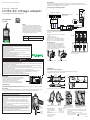
Description
The LV150-AC Voltage adapter is the interface between the Low Voltage electrical network and the
measurement and monitoring unit (LV150). For more information about LV150 installation and connections,
report to the LV150 Installation guide (ref: NHA92575-xx).
Installation
Guide
Installing the AC Voltage adapter on
DIN rail
External dimensions of the AC Voltage adapter
DM105381.eps
15 mm
0.59 in
7 mm
0.28 in
2
1
Click!
3
DANGER
HAZARD OF ELECTRIC SHOCK, EXPLOSION, OR ARC FLASH
bWear your personal protective equipment (PPE) and comply with the safe electrical work practices. See
NFPA 70E in the USA or applicable local standards.
bOnly qualifi ed electrical workers should install this equipment. Such work should be performed only after
reading this entire set of instructions.
bSwitch off the electric power supply of the LV150 and of all the devices to which the LV150 and the AC
Voltage adapter are connected before any handling or replacement operation.
bEnsure the LV Network is turned off before to install the AC Voltage adapter and making the connections
to the LV150 and the LV network.
bAlways use a properly rated voltage sensing device to confi rm that all power is off .
bDo not connect the AC Voltage adapter directly to the LV electrical network. Always use fuses and
disconnect switch (maximum voltage allowable on the AC Voltage adapter inputs : 600 VAC).
bNever short the secondary of a Voltage Transformer (VT).
Failure to follow these instructions will result in death or serious injury.
DM105380.eps
DE53833.eps
NOTICE
HAZARD OF INCORRECT VOLTAGE MEASUREMENTS
bDo not expose the device to conditions exceeding the electrical values
specifi ed in this document.
bStandby protection should be provided in accordance with national and
international cabling regulations.
bAn appropriate electrical disconnecting device must be installed in the
building in question.
bCheck that the connections correspond to the recommended
cables before powering up the equipment.
bUse appropriate tools to perform cabling on the connectors (suitable
screwdriver, crimped end-pieces, etc.).
Failure to follow these instructions can result in equipment damage.
NOTE
Electrical equipment should be installed, operated,
serviced, and maintained only by qualifi ed personnel. No
responsibility is assumed by Schneider Electric for any
consequences arising out of the use of this material.
A qualifi ed person is one who has skills and knowledge
related to the construction, installation, and operation of
electrical equipment and has received safety training to
recognize and avoid the hazards involved.
Part number Designation
EMS59574 AC Voltage adapter high insulation for
LV150 (10 KV/1 sec, 6 KV/1 mn)
PowerLogic
LV150
012345
YYMMXXXX
L1
L3
L2
Black
Brown
Grey
Blue
N
Ethernet cable
PowerLogic
AC Voltage adapter
RJ45
3 phases + Neutral
0.5 A fuses and
disconnect
switch
LV150
U
Nominal voltage:
b190 to 415 VAC (phase to
phase voltage)
DM105368.ai
Connecting AC Voltage adapter
Installation
Installing AC Voltage adapter
The AC Voltage adapter is fastened to a DIN rail. No tool is needed for mounting.
Simply clip it in order to fasten it as shown below.
NT0039300-01
PowerLogic
LV150
012345
YYMMXXXX
3
PowerLogic
LV150
012345
YYMMXXXX
2
PowerLogic
LV150
012345
YYMMXXXX
1
1
UU
U
21 3
L
V150
DM105375.eps
Connection of the Ethernet RJ45 cable to
the right LV150 voltage input depending to
the channel number.
Identifi cation
The serial number of the AC Voltage adapter is formed as follows: Year - Week - Work order, eg 17340265
(265th product manufactured, week 34 of the year 2017)
Grounding
The LV150-AC Voltage adapter doesn't need to be connected to the ground. The ground connection on front
panel only corresponds to a measuring ground which is not used with LV150-AC Voltage adapter.
NT0039300-01
As standards, specifi cations and designs change from time to
time, always ask for confi rmation of the information given in
this publication.
Publication : Schneider Electric
Production : Schneider Electric
Printing : Schneider Electric
This document was printed on
environmentally friendly paper
35 rue Joseph Monier
92500 Rueil Malmaison -
France
Phone: +33 (0)1 41 29 70 00
www.se.com
© 2023 Schneider Electric.
All Rights Reserved.
Schneider Electric
Made in France
Calibration
The values shown on the product label allow calibration of
the AC Voltage adapter for each phase and neutral. This
calibration operation is carried out during T300
commissioning via the T300 Web server.
Refer to the T300 User Manual for details about this
operation (Ref: NT00378-xx - "T300 settings" chapter).
Ch1 150.73
Ch2 150.64
Ch3 150.45
Ch4 150.55
EMS59574
RN17180064
NOTICE
HAZARD OF INSULATION DEGRADATION
bDo not connect the LV150-AC Voltage adapter to the ground via the
measuring ground connection on front panel. Connecting this point to the
ground could reduce the insulation of 10 KV/1 sec (6 KV / 1 mn) on the
voltage inputs.
bIn case the LV ground is diff erent from the LV150 ground (eg MV
ground), the AC Voltage adapter requires certain installation rules to
ensure the 10 KV / 1 sec (6 KV / 1 mn) product insulation (see drawing
opposite):
- Distance of 25 mm (0.984 in) between the measuring ground input
and any conductive part.
- Respect of the 10 KV/1 sec (6 KV / 1 mn) insulation on the RJ45 cable
(link between AC Voltage adapter and LV150). If the RJ45 Ethernet
cable doesn't naturally conform to the 10 KV insulation, install an
additional insulating sheath around the cable. Please note that the
Ethernet cable proposed as standard accessory with the LV150-AC
Voltage adapter respects 2 KV insulation only.
Failure to follow these instructions can result in equipment damage.
Installing the AC Voltage
adapter on structure
mounting (collar width to
be used: 4 mm / 0.16 in)
Installing the AC Voltage
adapter with telequick grid
mounting (screws to be used :
4 mm / 0.16 in).
DM105382.eps
DM105385.eps
DM105379.ai
Screw
Screw
RJ45 locking
The RJ45 input of the AC Voltage adapter can
be locked in the open or closed position by
placing a seal in the hole marked with a lock
symbol (see drawing below). This allows you to
lock the RJ45 connector of the Ethernet cable in
its slot or prevent its connection.
DM105383.ai
Connecting Voltage inputs
Ethernet RJ45 cable can be supplied as an
accessory.
The Ethernet RJ45 cable is to be connected to
LV150.
Length maximum: 4 m
Cable type (S/STP or S/FTP):
bCCA770 - 0.6 m / 1.97 ft (reference: 59660)
bCCA772 - 2 m / 6.56 ft (reference: 59961)
bCCA774 - 4 m / 13.12 ft (reference 59962)
DM105384.eps
05-2023
Locked in close position Locked in open position
Distance:
25 mm
0.984 in
Insulating
sheath (if
required)
Schneider Electric
Limited
Staff ord Park 5
Telford, TF3 3BL
United Kingdom

NT0039300-01
En raison de l’évolution des normes et du matériel, les
caractéristiques indiquées par les textes et les images de ce
document ne nous engagent qu’après confi rmation par nos
services.
Publication : Schneider Electric
Production : Schneider Electric
Impression : Schneider Electric
Ce document a été imprimé
sur du papier écologique
35 rue Joseph Monier
92500 Rueil Malmaison - France
Tél : +33 (0)1 41 29 70 00
www.se.com
© 2023 Schneider Electric.
Tous droits réservés.
Schneider Electric
Made in France
90 mm
3.54 in
52 mm
2.04 in
25 mm
0.98 in
38 mm
1.49 in
120 mm
4.72 in
LV150-Adaptateur tension
Gestion des réseaux électriques MT
Gamme PowerLogicTM T300
Unité de surveillance de l’alimentation basse tension
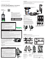
Description
L'adaptateur tension-LV150 est l'interface entre le réseau électrique Basse Tension et l'unité de surveillance
et de mesures (LV150). Pour plus d'informations sur l'installation et le raccordement du LV150, consulter le
Guide installateur LV150 (réf : QGH27524-xx).
Guide
installateur
Installation de l'adaptateur tension sur
rail DIN
Dimensions externes de l'adaptateur tension
DM105381.eps
15 mm
0.59 in
7 mm
0.28 in
2
1
Click!
3
DANGER
RISQUE D’ÉLECTROCUTION, D’EXPLOSION OU D’ARC ÉLECTRIQUE
bRevêtez vos équipements de protection individuelle (EPI) et respectez les procédures de sécurité.
Reportez-vous aux normes locales d’installation en vigueur.
bSeul une personne qualifi ée peut installer ce matériel. Ce travail ne doit être eff ectué qu'après avoir lu les
instructions présentes dans ce document.
bCouper l’alimentation l’électrique du LV150 et de tous les équipements auxquels le LV150 et l'adaptateur
tension sont raccordés avant toute manipulation ou remplacement.
bUtilisez un Vérifi cateur d’Absence de Tension (VAT) afi n de s' assurer que le dispositif est hors tension.
bNe pas raccorder l'adaptateur tension directement sur le réseau électrique BT. Toujours utiliser des
fusibles et un organe de coupure (tension maximale admissible sur les entrées de l'adaptateur : 600 Vca).
bNe jamais court-circuiter le secondaire d'un transformateur de tension (VT).
bS’assurer que le réseau BT est bien hors tension avant d’installer les tores sur les câbles phase et
d’eff ectuer le raccordement sur le module LV150.
Le non-respect de ces directives engendrera des blessures corporelles graves ou la mort.
DM105380.eps
DE53833.eps
NOTICE
RISQUE DE MESURE INCORRECTE
bN’exposez pas le dispositif à des conditions dépassant les valeurs
électriques précisées dans ce document.
bLe dispositif doit être installé verticalement dans une armoire électrique,
selon les réglementations locales en vigueur.
bUn dispositif de déconnexion électrique adapté doit être installé dans le
bâtiment concerné.
bVérifi er que les raccordements correspondent aux câblages
recommandés avant de mettre l’équipement sous-tension.
bUtiliser des outils appropriés pour réaliser le câblage sur les
connecteurs (tournevis adapté, embouts sertis, etc.).
Le non-respect de ces directives peut provoquer des dommages sur
l'équipement.
NOTE
Seul un personnel qualifi é doit eff ectuer l’installation,
l’utilisation, l’entretien et la maintenance du matériel
électrique. Schneider Electric n’assume aucune
responsabilité concernant les conséquences éventuelles de
l’utilisation de cette documentation.
Par personne qualifi ée, on entend un technicien compétent
en matière de construction, d’installation et d’utilisation des
équipements électriques et formé aux procédures de
sécurité, donc capable de détecter et d’éviter les risques
associés.
Référence Désignation
EMS59574 Adaptateur tension haute isolation
pour LV150 (10 KV/1 sec, 6 KV/1 mn)
PowerLogic
LV150
012345
YYMMXXXX
L1
L3
L2
Noir
Marron
Gris
Bleu
N
Câble Ethernet
PowerLogic
AC Voltage adapter
RJ45
3 phases + Neutre
Fusibles 0,5 A
et organe de
coupure
LV150
U
Tension nominale :
b190 à 415 VAC (tension
composée)
DM105367.ai
Raccordement de l'adaptateur tension
Installation
Installation de l'adaptateur tension
L'adaptateur tension se fi xe sur un rail DIN. Aucun outil n’est nécessaire à la fi xation.
Il suffi t de le clipser pour le fi xer comme indiqué ci-dessous.
NT0039300-01
PowerLogic
LV150
012345
YYMMXXXX
3
PowerLogic
LV150
012345
YYMMXXXX
2
PowerLogic
LV150
012345
YYMMXXXX
1
1
UU
U
21 3
L
V150
DM105375.eps
Branchement du connecteur RJ45 sur
l'entrée tension du bon module LV150 en
fonction du numéro de voie.
Identifi cation
Le numéro de série de l'adaptateur tension est composé comme suit : Année - Semaine - Ordre de
fabrication
ex :17340265 (265 ème produit fabriqué, semaine 34 de l’année 2017)
Mise à la terre
L'adaptateur tension-LV150 n'a pas besoin d'être raccordé à la terre. La connexion de terre sur la face avant
de l'adaptateur correspond uniquement à une terre de mesure qui n'est pas utilisée sur l'adaptateur
tension-LV150.
Calibration
Les valeurs indiquées sur l'étiquette produit permettent de
réaliser la calibration de l'adaptateur tension pour chaque
phase et le neutre. Cette opération de calibration du produit
s'eff ectue lors de la mise en service du T300 via le serveur
Web T300. Consulter le Manuel Utilisateur T300 pour le
détail concernant cette opération (Réf : NT00378-xx - cha-
pitre "Paramétrage du T300").
Ch1 150.73
Ch2 150.64
Ch3 150.45
Ch4 150.55
EMS59574
RN17180064
NOTICE
RISQUE DE DEGRADATION DE L'ISOLEMENT
bNe pas connecter l'adaptateur tension-LV150 à la terre via la connexion
de terre de mesure en face avant du produit. Cela pourrait réduire
l'isolement de 10 KV / 1 sec (6 KV / 1 mn) sur les entrées tension.
bSi la terre BT est diff érente de la terre du LV150 (ex : terre MT),
l'adaptateur tension nécessite certaines règles d'installation qu'il convient
de respecter pour garantir l'isolement 10 KV / 1 sec (6 KV/1 mn) du produit
(voir dessin ci-contre) :
- Distance séparatrice de 25 mm (0.984 in) entre l'entrée terre de
mesure de l'adaptateur tension et toute partie conductrice.
- Respect de la tenue d'isolement 10 KV/1 sec (6 KV / 1 mn) du câble
RJ45 de liaison entre l'adaptateur et le LV150, par rapport à la masse
BT. Si le câble Ethernet RJ45 ne respecte pas naturellement l'isole-
ment de 10 KV, installer une gaine isolante supplémentaire autour du
câble. Notez que le câble Ethernet proposé comme accessoire par
défaut respecte un isolement de 2KV uniquement.
Le non-respect de ces directives peut provoquer des dommages sur
l'équipement.
Installation de l'adaptateur
tension sur structure
(largeur de collier à utiliser :
4 mm / 0.16 in)
Installation de l'adaptateur
tension sur grille métalique (vis
à utiliser : 4 mm / 0.16 in).
DM105382.eps
DM105385.eps
DM105379.ai
Vis
Vis
Verrouillage du connecteur RJ45
L'entrée RJ45 de l'adaptateur tension peut être
verrouillée en position ouverte ou fermée, en plaçant
une scellée dans le trou repéré par un symbole de
cadenas (voir dessin ci-dessous). Cela permet de
verrouiller le connecteur RJ45 du câble Ethernet dans
son logement ou d'empêcher sa connexion.
DM105383.ai
Connexion des entrées tension
Le câble Ethernet RJ45 peut-être fourni en tant
qu'accessoire.
Le câble Ethernet RJ45 est à connecter au
LV150.
Longueur maximum: 4 m
Type de câble (S/STP ou S/FTP):
bCCA770 - 0.6 m / 1.97 ft (référence: 59660)
bCCA772 - 2 m / 6.56 ft (référence: 59961)
bCCA774 - 4 m / 13.12 ft (référence 59962)
DM105384.eps
Verrouillé en position
fermée
Verrouillé en position
ouverte
Distance:
25 mm
0.984 in
Gaine
isolante
(si neces-
saire)
Staff ord Park 5
Telford, TF3 3BL
United Kingdom
Schneider Electric
Limited
05-2023
-
 1
1
-
 2
2


Schneider Electric PowerLogic LV150 -AC Voltage adapter Guide d'installation
- Taper
- Guide d'installation
dans d''autres langues
Documents connexes
-
Schneider Electric PrismaSeT P Instruction Sheet
-
-
-
-
-
-
-
-
-