Schneider Electric PowerLogic P5 Instruction Sheet
- Taper
- Instruction Sheet

PowerLogic
!
ON
0 A
0 A
0 A
Bay
IA
IB
IC
f - -.- - - Hz
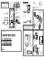
Navigation keyboard
and validation key
Standard configuration
Programmable LEDs
Control buttons
DI / DO
CB Open
CB Close
Green
1 2 3 4 5 6
CB Closed
TCS Alarm
I Trip IN Trip
Therm Alarm
Red
Yellow
B
4/4
UNINTENTIONAL DEVICE OPERATION
This device requires advanced knowledge of the design
and setting of protection systems. Only persons with such
knowledge are allowed to configure and set this device.
Failure to follow these instructions can result in
death, serious injury or equipment damage.
WARNING
Open
Close
1
OFF
OFF ON --
--
No alarm Old Alarm New alarm
No trip Trip
In service Maintenance Test mode
ON
Home key
Handle
Handle lock
Shutter Insert the label
Programmable LEDs
Jean-Marc
is perfect
Linda
is a Queen
3
Reset key
DI1 DI2 DI3 DI4 DO3 WDDO2DO1
FreeCB closeCB open CB trip CB close WatchdogCB trip lockout
Information key
Open key
Close
OFF
ON Remote
Local control key
P5U20
Green
1 2 3 4 5 6
CB Closed
TCS Alarm
Red
Yellow
P5V20
V Trip VN Trip f Trip
!
Stick the label
2
4
5
Remote mode
Local
F1
Function key
ON
Flash
05/2023
Schneider Electric Industries SAS
35 rue Joseph Monier
92500 Rueil-Malmaison
France
www.se.com
PowerLogicTM P5x20
1/4
Protection relays
Identification
Unpacking
P5 100-230V AC
24-250V DC
S/N:P5X20XXXXXXXXXX
50-60Hz
Reference
Power supply
voltage
Serial number
Access to
product website
Instruction sheet
Retain for future use
Go to www.se.com
to download the PowerLogicTM P5
user manuals and other documents.
This device must be installed
and serviced by qualified
electrical personnel.
Schneider Electric cannot be
held responsible for failure to
follow the instructions given on
this instruction sheet.
IMPORTANT NOTE
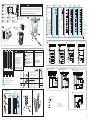
224
8.82
174
6.85
Rear panel
connection
instructions
mm
in.
3.4
0.13
5.0 ± 061
03.6 2.0 ±
2.761
85.6
100 ± 0.5
3.94 ± 0.2
51.8
2.04
102
4.01
5.0 ± 502
70.8 2.0 ±
130 ± 0.5
5.12 ± 0.2
180
80.7
The PowerLogic P5x20 is
designed for use on a flat
surface of a Type 1
enclosure, as defined by
Underwriters Laboratories
Inc. (UL).
NOTICE
Our products leave our factory in closed, sealed original packaging. At delivery, if
the packaging is opened or the seal is broken, Schneider Electric must be
informed.
Failure to follow these instructions can result in compromised confidentiality and
authenticity of the information contained in the products.
2
03/2014
Schneider Electric Industries SAS
35 rue Joseph Monier
92500 Rueil-Malmaison
France
www.schneider-electric.com
PowerLogic P5
© 2014 Schneider Electric.
All rights reserved.
Protection relay
1 Protection relay
2 Certificate of compliance
xxxxxxx
4 Instruction sheet
5 Connector A cabling kit
6 Connector(s)
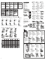
Equipment receipt
Equipment receipt
The code image(front panel of the relay
gives a direct access to your relay’s
website
en
This device must be installed
and serviced by qualified
electrical personnel.
Schneider Electric cannot be held
responsible for failure to follow
the instructions given on this
instruction sheet.
en
IMPORTANT NOTE
Instruction sheet
Retain for future use
Go to www.schneider-electric.com
to download the PowerLogic P5
reference manual and other
documents.
2
3
5
6
en
1
3
5
1
Protection relay
Certificate of compliance
Instruction sheet
Connector A cabling kit + labels
(4a: for CT/VT version;
4b: for LPCT/LPVT version)
Connector(s)
1
2
3
4a/4b
5
4b
4a
The code image (front panel of the relay) gives a direct access
to your protection relay’s website.
Product technical data and a copy of Certificate of Conformity
can be found there.
© 2023 Schneider Electric.
All rights reserved.
LISTED
IND. CONT. EQ.
E354250
Free
NHA31477+25
COMPROMISED CONFIDENTIALITY AND AUTHENTICITY OF THE INFORMATION

FIRE
Tighten the terminal screws
with a minimum torque of 1
N•m (8.85 lb-in).
Protect the power supply circuit
against overcurrents
Failure to follow these
instructions can result in injury
or equipment damage.
CAUTION
DAMAGE TO THE RELAY
Power off the relay before
removing or replacing any part
or module.
Failure to follow these
instructions can result in
equipment damage.
NOTICE
Connector A
3
2/4
The PowerLogic P5x20 is designed for use in a pollution degree 2 environment as defined by Underwriters Laboratories Inc. (UL).
DANGER
HAZARD OF ELECTRICAL
SHOCK, EXPLOSION OR ARC
FLASH
Connect the relay to earth/ground
with nut and washer.
Use the appropriate (3 or 4
terminal) copper jumper for
common connection.
After cabling, protect the rear
connector “A” with the two
protection caps.
Failure to follow these instructions
will result in death or serious injury.
HAZARD OF ELECTRICAL SHOCK, EXPLOSION OR ARC FLASH
Turn off all power supplying this equipment before working on or inside the equipment.
Always use an appropriate voltage detection device to confirm no presence of any voltage.
Replace all devices, doors and covers before switching on power to this equipment.
Failure to follow these instructions will result in death or serious injury.
DANGER
1
2
1...1.2 N•m
(8.85...10.62 lb-in)
3/4
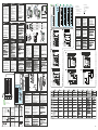
ETH: Ethernet module
SRL: Serial communication module
EXT: Extension interface
M
N
P
MEthernet HSR/PRP module
N
B
1
3
5
7
9
11
13
15
17
1
2
3
4
5
6
7
8
9
10
11
12
13
14
15
16
17
18
19
20
1
2
3
4
5
6
7
8
9
10
11
12
13
14
15
16
17
18
19
20
2
4
6
8
10
12
14
16
18
MNP
CA
A
2
1
3
1
2
3
4
L1
L2
L3
V1
V2
V3
V4
A
1
2
3
CT/VT version
0.2...2.5 mm2
AWG 24...14
0.2...1.5 mm2
AWG 24...16
1...1.2 N•m
8.85...10.62 Ib-in
0.4...0.5 N•m
3.5...4.4 Ib-in
M4
2.5 mm
<50 cm (<20 in.)
3/32 in.
6.5 mm N° 2
1/4 in.
Ø 4 mm
Ø 0.16 in.
A
12 mm
0.5 in.
×1
×2
Ø 4 mm
Ø 0.16 in.
Ø <8.5 mm
Ø <0.33 in.
B, C
0.5...1.5 mm2 (AWG 20...16)
1.5...2.5 mm2 (AWG 16...14)
2.5...6 mm2 (AWG 14...10)
1...1.2 N•m
8.85...10.62 Ib-in
LPCT/LPVT version
P5U20 only
ALPCT/LPVT
P5U20 only
1
2
3
4
20 A
2 A
IA
IB
IC
V1
V2
V3
V4
AP5V20 only
Not used
12
11
14
13
15
16
17
18
10
9
4
3
6
5
7
8
2
1
V1
V2
V3
V4
IA
IB
IC
2 A
20 A
IA
IB
IC
IN
.sens
IN
12
11
14
13
15
16
17
18
10
9
4
3
6
5
7
8
2
1
AP5U20 only
Not used
IN Standard earth fault
IN
.sensSensitive earth fault
Option
Terminal
DO Digital Output
DI Digital Input
- S
Signalling, 2 A perm.
Control / Trip,8 A perm.- C
High Speed / high break,
Trip, 10 A perm.
- HS
WD Watchdog
C
DI1
DI2
DI3
DI4
DI5
DI6
DO1
DO2
DI7
DI8
DI9
DI10
DI11
DI12
DO3
DO4
S
S
S
S
1
2
3
4
5
6
13
14
15
16
17
18
19
20
7
8
9
10
11
12
C
DI1
DI2
DI3
DI4
DI5
DI6
DO1
DO2
DO3
DO4
S
S
S
S
1
2
3
4
5
6
13
14
15
16
17
18
19
20
7
8
9
10
11
12
B
DI1
DI2
DO3
DO2
DO1
WD
DI3
DI4
1
2
3
4
5
6
13
14
15
16
17
18
19
20
7
8
9
10
11
12
C
C
C
C
24-250 V DC
100-230 V AC
C
DO1
DO3
DO4
DI5
DO2
DO5
DI1
DI2
DI3
DI4
C
C
C
C
C
HS
HS
1
2
3
4
5
6
13
14
15
16
17
18
19
20
7
8
9
10
11
12
0.4 N•m
(3.5 lb-in)
x 2
1 N•m
(8.85 lb-in)
22
11
3
Take care to align the
terminal with the socket
to guarantee good insertion.
en
Prenez soin d’aligner le
connecteur avec le
bornier afin de garantir une
bonne insertion.
fr
Achten Sie auf eine
korrekte Ausrichtung
des Klemmenblocks bei der
Montage.
de
Assicurarsi di
allineare la
morsettiera con la foratura
durante l’inserimento.
it
Asegúrese de
alinear el terminal
con el enchufe para
garantizar una correcta
inserción.
es
Tome cuidado
para alinhar o
terminal com o soquete para
garantir uma boa inserção .
Zadbaj o spasowanie
złącza do gniazda
aby zagwarantować dobre
połączenie.
pl Для корректной
установки выдвижной
части необходимо следить за
правильным ее положением
соответствующим разъемам.
ru
Röleyi gömülü kasaya yerleştirirken
cihazın terminal bloğu ile
hizalanmış olduğuna dikkat edin.
tu
zh
br/p
(Only with flush
mounting accessory,
Ref: REL51032)
4
3
2.5...6 mm2
AWG 14...10
3.3...6 mm2
AWG 12...10
IEC:
ANSI:
3 × 1/5 A CTs + 1 neutral CSH
A18
A17
A16
A15
S1
S1
S1
S1
A14
A13
A12
A11
A10
A9
A
B
C
A
B
C
1/5 A
CSH
IA
IB
IC
20A/2A
IN
21 43
A4
A3
A2
A1
S1
RJ45
RJ45
CSH
IA
IB
IC
20A/2A
RJ45
3 x LPCT + 1 neutral CSH
Current transformer (CT)
Voltage Transformer (VT)
LPCT
LPVT
Core balance CT
(i.e. CSH200)
- CT & VT connections are typical only.
- Earth / ground terminals are typical only.
- Wiring diagrams represent
protection relay not energised.
IN
IN
IN
53 phase-to-ground voltage
+ 1 neutral voltage
A
B
C
A4
A3
A6
A5
A7
A8
A2
A1
V1
V2
V3
V4
A
B
C
A4
A3
A6
A5
A7
A8
A2
A1
V1
V2
V3
V4
63 phase-to-ground voltage
+
1 phase-to-phase voltage
V1
V2
V3
V4
A4
A3
A6
A5
A7
A8
A2
A1
A
B
C
72 phase-to-phase voltage + 1 neutral voltage
+ 1 phase-to-phase voltage
3 × 1/5 A CTs + 1 neutral 1/5 A CT + 1 × 1 A CT
A18
A17
A16
A15
S1
S1
S1
S1
S1
A14
A13
A12
A11
A10
A9
1/5 A
1/2/5 A
1 A
A
B
C
IA
IB
IC
A18
A17
A16
A15
S1
S1
S1
S1
A14
A13
A12
A11
A10
A9
1/5 A
1 A
A
B
C
IA
IB
IC
IN
IN
.sens
IN
IN
.sens
3 phase-to-ground LPVT + 1 phase-to-ground LPVT
8
LPVT hub
LPVT hub
LPVT A
LPVT B
LPVT C
A
B
C
RJ45
RJ45 V1, V2, V3
V4

4/5 1/5
fr Instruction de service
À conserver pour usage ultérieur
Visitez le site
www.se.com
pour télécharger le manuel de
référence PowerLogic P5 et
d’autres documents
it Scheda di istruzioni
Da conservare per impieghi
futuri
Per scaricare il manuale di
riferimento PowerLogic P5 ed altra
documentazione visitare il sito
www.se.com .
de Anleitung
Zur späteren Verwendung
aufbewahren
Das Referenzhandbuch der
PowerLogic P5 sowie weitere
Dokumente stehen unter
www.se.com
zum Download zur Verfügung.
es
L’installation et l'entretien de
cet appareil doivent être effectués
par des professionnels de
l’électricité.
Le non-respect des indications de
la présente instruction de service
ne saurait engager la
responsabilité du constructeur.
NOTE IMPORTANTE
L’installazione e la manutenzione
del dispositivo si devono affidare a
elettricisti qualificati.
Il costruttore non si ritiene
responsabile per il mancato
rispetto delle istruzioni fornite in
questa scheda.
IMPORTANTE
Dieses Gerät darf nur von
qualifizierten Elektrofachleuten
installiert und gewartet werden.
Der Hersteller übernimmt keine
Verantwortung für Konsequenzen,
die sich aus der Nichtbefolgung
der Anweisungen in dieser
Anleitung ergeben.
WICHTIGER HINWEIS
pl
www.se.com
PowerLogic
P5.
instalowane oraz serwisowane
przez wykwalifikowany personel.
Schneider Electric nie bierze
nieprzestrzegania uwag
zawartych w tym dokumencie.
UWAGA
ru
www.se.com
Visite el sitio Web www.se.com
para
referencia PowerLogic P5 así como otros
documentos.
Instrucciones de servicio
Debe conservarse para un uso
posterior
La instalación y el mantenimiento
de este equipo deben ser
llevados a cabo por profesionales
de la electricidad.
El fabricante no asumirá ninguna
responsabilidad por las
consecuencias derivadas del
incumplimiento de las
instrucciones de este manual.
OBSERVACIÓN IMPORTANTE
Identifikation
1 Referenza
2 Serial number
3 Accesso al sito internet del
1 Referência
2 Número serial
3 Acesso ao site do produto
4 Tensão de alimentação
5 Instruções para conexão
na parte traseira
1 Referencia
2 Número de serie
3 Acceso al sitio web del producto
4 Tensión de alimentación
5 Instrucción para conexión
en parte trasera
1
2
3
4
5
1 Referans
4 Besleme gerilimi
5
Identificación
Identification
1 Référence
2 Numéro de série
3 Accès au site internet du produit
4 Tension d'alimentation
5 Instruction pour connexion
en face arrière
es
tu
de it
pl
ru zh
fr Identificazione
Identificação
P5 100-230V AC
24-250V DC
S/N:P5X20XXXXXXXXXX
50-60Hz
4
2
3
5
1
pl
Relais de protection
it
de
fr
tu
Relè di protezione
Schutzrelais
Relé de protección
es
Relé de proteção
zh
Folha de instruções Conserve
para utilização futura
Visite
www.se.com
para transferir o manual de
referência do PowerLogic P5 e outros
documentos.
A instalação e manutenção deste
dispositivo deve ficar a cargo de
profissionais qualificados
(electricistas).
O fabricante não poderá ser
considerado responsável no caso
da não observância das
instruções presentes nesta folha.
NOTA IMPORTANTE
www.se.com
web sitesinden
PowerLogic
P5 serisi
servisi yetkili elektrikçi personel
Bu dökümanda yer alan ürün
hallerinde Schneider Electric
üretici olarak sorumlu tutulamaz.
www.se.com
PowerLogicTM P5x20
1 Produktbezeichnung
2 Seriennummer
3 Link zur Produktwebsite
4 Versorgungsspannung
5 Rückseitige
Verbindungsanweisungen
br/p
br/p
br/p
LISTED
IND. CONT. EQ.
E354250
prodotto
4 Tensione d'alimentazione
5 Istruzioni di collegamento dei
panelu
tylnego
connettori posteriori
br/p
DI1 DI2 DI3 DI4 DO3 WDDO2DO1
Position disjoncteur ouvert Déclenchement
disjoncteur Fermeture du
disjoncteur Chien de garde
Verrouillage enclenchement
disjoncteur
Leistungsschalter
offen (Status) Leistungsschalter
öffnen Leistungsschalter
schließen Watchdog
Leistungsschalter-Auslösesperre
Interruttore aperto Apertura interuttore Chiusura
interruttore "Watchdog"Blocco chiusura interuttore
Disyuntor estado abierto Disparo de disyuntor Cierre de
disyuntor WatchdogBloqueo de cierre de disyuntor
Status disjuntor aberto Disparo de disjuntor Com. fecha
disjuntor Cão-de-guarda
Bloqueio de disparo de disjuntor
Stan wy Otwarcie wy WatchdogLokalne wy czenie wy cznika
Kesici açma Kesici kapama WatchdogKesici açma kilidi
Position disjoncteur
fermé
Leistungsschalter
geschlossen (Status)
Chiusura
interruttore
Cierre de
disyuntor
Com. fecha
disjuntor
Kesici kapama
IN Entrée courant terre standard
Entrée courant terre très sensible
WD Chien de garde
DI, DO Entrée logique, sortie logique
Borne
Transformateur de courant (TC)
Transformateur de tension (TT)
TC Tore homopolaire
(ex.: CSH200)
Option
- Raccordement TC et TT pour exemple.
- Raccordement terre pour exemple.
- Les schémas de connexion sont
représentés relais de protection hors tension.
LPCT
LPVT
IN
DI, DO
Standard Erdschlussstrom
IN.sens sehr empfindlicher Erdschlussstrom
WD Watchdog
Digitaleingang, -ausgang
Klemme
Stromwandler (StW)
Spannungswandler (SpW)
Summenstromwandler
(z. B. CSH200)
Option
- StW- und SpW-Anschlüsse exemplarisch
- Erdungsanschlüsse exemplarisch
- Anschlusspläne stellen das spannungs-
freie Gerät dar
LPCT
LPVT
IN Corrente di terra standard
WD "Watchdog"
Corrente di terra molto sensibile
DI, DO Ingresso digitale, Uscita
digitale
Morsetti
Trasformatore di corrente (TA)
Trasformatore di tensione (TV)
TA toroidale omopolare
(es. CSH200)
Opzione
- Collegamenti Ta e TV solo a titolo d'esempio
- Collegamento a terra a titolo d'esempio.
- Gli schemi e le connessioni sono
rappresentati a relè fuori tensione.
LPCT
LPVT
IN Corriente de fallo a tierra estándar
Corriente de fallo a tierra muy sensible
WD Watchdog
DI, DO
Entrada digital, Salida digital
Borna
Transformador de intensidad (TI)
Transformador de Tensión (TT)
Toroidal homopolar
(ejemplo: CSH200)
Opcional
- Las conexiones de los TIs y los TTs son
un ejemplo
- Las conexiones de las bornas a tierra son
un ejemplo
- Los diagramas de conexión están representados
con el relé no energizado.
LPCT
LPVT
IN Corrente de defeito homopolar
padrão
Corrente de defeito homopolar
muito sensível
WD Cão-de-guarda
DI, DO Entrada digital, Saída digital
Terminal
Transf. de corrente (TCs)
Transf. de tensão (TPs)
Transformador toroidal
(i.e. CSH200)
Opcional
- As conexões TP & TC são exemplos
- As conexões de terra são exemplos
- Os esquemas de ligação são
representados com o relé desligado
br/p
LPVT
LPCT
IN
WD Watchdog
DI, DO
Terminal
Gerilim Trafosu (GT)
Rezidüel AT
(i.e. CSH200)
Opsiyon
enerjisizken ki halini temsil etmektedir.
LPCT
LPVT
IN Standardowe
Bardzo czu
WD Watchdog
DI, DO
Zacisk
(np. CSH200)
Opcja
bez zasilania
przeka nikowe
Czujnik pr dowy LPCT
Czujnik napi ciowy LPVT
IN
WD
DI, DO
IN
WD
DI, DO
( CSH200)
-
-
-
NOTE NOTA
UWAGA
AVISO
Nuestros productos salen de nuestra fábrica
en su embalaje original cerrado y sellado. Si
a la entrega el embalaje está abierto o el
sellado está roto, se debe informar a
Schneider.
El no respetar estas instrucciones puede
comprometer la confidencialidad y
autenticidad de la información contenida
en los productos.
ATENCIÓN
edilmesi durumunda Schneider Electric
bilgilendirilmelidir.
olabilir.
fr it es
pl rutu zh
br/p
Nos produits partent de notre usine dans
son emballage d’origine fermé et scellé. Si
à la livraison l’emballage est ouvert ou
détérioré, Schneider Electric doit être
informé.
Le non-respect de cette instruction peut
compromettre la confidentialité et
authenticité des informations contenues
dans les produits.
Nossos produtos saem da nossa fábrica em
embalagens originais fechadas e lacradas.
Na entrega, se a embalagem estiver aberta
ou o lacre estiver quebrado, a Schneider
Electric deve ser informada.
O não cumprimento desta instrução
pode resultar em comprometimento da
confidencialidade e autenticidade das
informações contidas nos produtos.
Schneider Electric.
I nostri prodotti lasciano la fabbrica nel loro
imballaggio originale con sigillo di sicurezza.
Informare Schneider Electric se, al momento
della consegna, l’imballaggio o il sigillo
risultano compromessi.
L’omissione di tale procedura può
l’autenticità delle informazione contenute
nel prodotto stesso.
de
Unsere Produkte verlassen unser Werk in
geschlossenen, versiegelten
Originalverpackungen.
produktach.
opakowanie zostanie otwarte lub plomba
Wolny
Libre
Frei
Libero
Libre
Livre
HINWEIS
Sind beim Erhalt der Lieferung die
Verpackungssiegel geöffnet, so sind
in den Produkten enthaltenen
Informationen nicht mehr sichergestellt.
tu
zh
Koruma rölesi
ru
05/2023
Schneider Electric Industries SAS
35 rue Joseph Monier, 92500 Rueil-Malmaison, France
www.se.com
4a
AçmaRozpakowanieDesempacotando
Déballage Auspacken Disimballaggio Desembalaje
es
tu
de it
pl ru zh
1 Relais de protection
2 Certificat de conformité
3 Instruction de service
4a Kit de câblage connecteur A
fr
1
Relé de protección
2 Certificado de conformidad
3 Instrucciones de servicio
4a Kit
de cableado conector A
1 Koruma rölesi
4a A tipi CT/VT bağlantısı için
1 Relé de proteção
2 Certificado de conformidade
3 Folhas de instruções
4a Kit de etiquetas e conector
1
2
3
4a A
1 Relè di protezione
2 Certificato di conformità
3 Schede di istruzioni
4a Kit di cablaggio connettore A
1 Schutzeinrichtung
2 Konformitätserklärung
3 Kurzanleitung
4a Zubehör für Klemmenblock A
br/p
+ etichette (versione con TA/TV)
4b Kit di cablaggio connettore A
+ etichette (versione con
LPCT/LPVT)
5 Connettore(i)
CT / VT
4b A
LPCT / LPVT
5
4a Z cze A zestawu
okablowania + etykiety
CT / VT)
4b Z cze A zestawu
okablowania + etykiety
CT / LPVT)
tipo A (Versão TC / TP)
4b Kit de etiquetas e conector
tipo A (Versão LPCT / LPVT)
5 Conector(es)
+ Etiquette (version CT/VT)
4b Kit de câblage connecteur A
+ Etiquette (version
LPCT/LPVT)
5 Connecteur(s)
+ Etikett (CT/VT Version)
4b Zubehör für Klemmenblock A
+ Etikett (LPCT/CPVT Version)
5 Klemmenblöcke
+ etiquetas (versi
ó
n TI / TT)
4b Kit de cableado conector A
+ etiquetas (versi
ón
LPCT /
LPVT)
5 Conector(es)
kablolama kiti (CT/VT sürüm)
4b A tipi CT/VT bağlantısı için
kablolama kiti (LPCT/LPVT sürüm)
5 Konnektörler (LPCT/LPVT)
10/2018
Schneider Electric Industries SAS
35 rue Joseph Monier
92500 Rueil-Malmaison
France
www.schneider-electric.com
PowerLogic P5
© 2018 Schneider Electric.
All rights reserved.
Protection relay
1 Protection relay
2 Certificate of compliance
xxxxxxx
4 Instruction sheet
5 Connector A cabling kit
6 Connector(s)
Equipment receipt
Equipment receipt
The code image (front panel of the relay)
gives a direct access to your relay’s
website
en
This device must be installed
and serviced by qualified
electrical personnel.
Schneider Electric cannot be held
responsible for failure to follow
the instructions given on this
instruction sheet.
en
IMPORTANT NOTE
Instruction sheet
Retain for future use
Go to www.schneider-electric.com
to download the PowerLogic P5
reference manual and other
documents.
2
3
5
6
en
1
Bay
0 A
0 A
0 A
0.00 A
34a
5
4b
1
2
Bay
0 A
0 A
0 A
0.00 A
© 2023 Schneider Electric.
All rights reserved.
Wolny
Libre
Frei
Libero
Libre
Livre
NHA31477+25
IN.sens
IN.sens
IN.sens
IN.sens
IN.sens
IN.sens
IN.sens
IN.sens
descargar el manual de
PowerLogic P5
ТОО «Шнейдер Электрик» Адрес: 050010, Казахстан, г.
Алматы, пр. Достык, д. 38, э. 5
Тел.: +77273572357, Fax: +77273572357
www.se.com

2/5
DIKKAT
UWAGAATTENÇÃO
RIESGO DE INCENDIO
Apriete los terminales de tornillo con
un par mínimo de 1 N•m (8,85 lb-in).
Proteja el circuito de alimentación
contra las sobreintensidades.
El uso indebido de estas
lesiones o daños en el equipo.
A
TENCIÓN
RISCO DE INCÊNDIO
Aperte os parafusos dos terminais
com um torque mínimo de 1 N•m
(8.85 lb-in).
Proteja a fonte de alimentação
contra sobrecorrentes
O descumprimento dessas
instruções podem causar ferimentos
e danos ao equipamento.
(8.85 lb-in).
momentem 1 N•m.
Zabezpiecz obwody zasilania
przed zwarciem.
RISCHIO D'INCENDIO
Serrare le viti dei connettori con una
coppia di serraggio de 1 N.m
(8.85 lb.in) minimo.
Proteggere il circuito d'alimentazione
contro le sovracorrenti.
Il mancato rispetto di queste istruzioni
materiali
(1 N•m)
1 N•m minimum tork ile terminal
devresini koruyunuz
olabilir
ATTENZIONEACHTUNG
RISQUE D’INCENDIE
Serrer les vis des connecteurs avec
un couple de serrage de 1 N•m
(8.85 lb-in) minimum.
Protéger le circuit de l’alimentation
contre les surintensités.
Le non-respect de ces instructions
peut entraîner des blessures ou des
dommages matériels
ATTENTION
RISQUE D’ELECTROCUTION,
D’EXPLOSION OU D’ARC
ELECTRIQUE
Coupez l’alimentation générale du
relais
de protection avant toute
intervention sur l’appareil.
Utilisez toujours un dispositif de
détection de tension approprié
pour confirmer l’absence de
tension.
Remettez en place tous les
équipements, les protection et le
volet avant de mettre sous tension.
Le non-respect de ces
instructions entraînera la mort
ou des lésions corporelles
DANGER GEFAHR PERICOLO
DANGER GEFAHR PERICOLO
PELIGRO PERIGO UWAGA
PELIGRO PERIGO UWAGA
TEHLIKE
RISQUE D’ELECTROCUTION,
D’EXPLOSION OU D’ARC
ELECTRIQUE
Connecter le relais à la terre
(écrou + rondelle)
Utiliser le cavalier en cuivre (3 ou
4 bornes) approprié pour
connecter le commun
En fin de câblage, protéger le
connecteur “A” avec les deux
protections
Le non-respect de ces instructions
peut entraîner la mort ou des
blessure .
RISCHIO DI FOLGORAZIONE,
ESPLOSIONE O ARCO
Connettere il relè a terra (dado +
rondella)
Utilizzare il ponticello in rame (3 o
4 morsetti) per collegare i comuni.
Alla fine del cablaggio, proteggere
il connettore "A" con le due
protezioni
Il mancato rispetto di queste
infortuni e anche mortali.
RIESGO DE DESCARGA ELÉCTRICA,
EXPLOSIÓN O ARCO
Conecte el rele de protección a tierra
por medio de tuerca y arandela.
Utilice el puente de cobre apropiado
(3 o 4 terminales) para la conexión
común.
Después de cablear debe protejer la
conexión trasera “A” con dos tapas
de protección.
Si no se respetan estas instrucciones,
incluso la muerte.
RISCO DE CHOQUE ELÉCTRICO,
EXPLOSÃO OU ARCO
Conectar o relé ao terra utilizando
porcas e arruelas.
Usar jumpers apropriados (3 ou 4
bornes) para interligar o cabo terra.
Após conexão dos cabos, proteja o
conector traseiro “A” com as duas
tampas de proteção.
O descumprimento dessas
instruções podem causar morte
LUB EKSPLOZJI
zaciski) do realizacji wspólnych
Po okablowaniu, zamaskuj
konektor “A” dwoma A
Kablaj bittikten sonar rölenin
edin.
konusu olabilir.
RISCHIO DI FOLGORAZIONE,
ESPLOSIONE O ARCO
Prima di effettuare lavori sul
dispositivo togliere
l’alimentazione elettrica.
Usare sempre uno strumento
adeguato per verificare
l’assenza di tensione.
Prima di riaccendere
l'apparecchiatura rimontare tutti i
dispositivi, gli sportelli e i
coperchi.
Il mancato rispetto di queste
RIESGO DE DESCARGA
ELÉCTRICA, EXPLOSIÓN O
ARCO
Corte la alimentación general del
equipo antes de manipularlo.
Utilice siempre un dispositivo de
detección de tensión apropiado
para confirmar la ausencia de
tensión.
Vuelva a colocar todos los
dispositivos, puertas y cubiertas
antes de volver a conectarlo.
Si no se respetan estas
instrucciones, se producirán
RISCO DE CHOQUE ELÉCTRICO,
EXPLOSÃO OU ARCO
Desligue toda a alimentação
eléctrica deste equipamento antes
de trabalhar no interior do
equipamento.
Utilize sempre um dispositivo de
detecção de tensão apropriado
para confirmar a ausência de
tensão.
Verifique todos os dispositivos,
portas e tampas antes de ligar a
alimentação neste equipamento.
instruções causará a morte ou
LUB EKSPLOZJI
zasilanie.
celu potwierdzenia jego braku.
PATLAMA VEYA ARK FLASH
önce, tüm güç besleyicilerini
için daima uygun bir voltaj ölçer
yaralanmalar söz konusu
olabilir.
TEHLIKE
3
1
2
A
1
2
3
1...1.2 N•m
(8.85...10.62 lb-in)
GEFÄHRDUNG DURCH
ELEKTRISCHEN SCHLAG,
EXPLOSION ODER LICHTBÖGEN
Vor Arbeiten an diesem Gerät muss
die gesamte Spannungsversorgung
ausgeschaltet sein.
Zum Feststellen der
Spannungsfreiheit ist ein geeignetes
Spannungsmessgerät zu verwenden.
Vor dem Einschalten der
Spannungsversorgung sind alle
Vorrichtungen, Klappen und
Abdeckungen wieder am Gerät
anzubringen.
Die Nichtbefolgung dieser
schweren Verletzungen.
GEFÄHRDUNG DURCH
ELEKTRISCHEN SCHLAG,
EXPLOSION ODER LICHTBÖGEN
Erden Sie die Schutzeinrichtung
mit Mutter und Unterlegscheibe.
Die Stromwandleranschlüsse sind
mit der 3- oder 4-poligen Brücke
kurzzuschließen.
Schützen Sie nach dem
Verdrahten den rückseitigen
Klemmenblock A mit dem
Berührungsschutz.
Die Nichtbefolgung dieser
schweren Verletzungen.
BRANDGEFAHR
Ziehen Sie die Befestigungs-
schrauben am Klemmenblock mit
einem Anziehdrehmoment von mind.
1 N•m (8,85 lb-in) fest.
Schützen Sie den Stromversorgungs-
kreis gegen Überstrom.
Die Nichtbefolgung dieser
Anweisungen kann zu Verletzungen
224
8.82
174
6.85
mm
in.
3.4
0.13
51.8
2.04
5.0 ± 061
6.30
2.761
85.6
100 ± 0.5
3.94
180
7.08
102
4.01
5.0 ± 502
70.8 2.0 ±
130 ± 0.5
5.12
B
1
3
5
7
9
11
13
15
17
2
4
6
8
10
12
14
16
18
MNP
CA
1
2
3
4
5
6
7
8
9
10
11
12
13
14
15
16
17
18
19
20
1
2
3
4
5
6
7
8
9
10
11
12
13
14
15
16
17
18
19
20
0.2...2.5 mm2
AWG 24...14
0.2...1.5 mm2
AWG 24...16
1...1.2 N•m
8.85...10.62 Ib-in
0.4...0.5 N•m
3.5...4.4 Ib-in
M4
2.5 mm
<50 cm (<20 in.)
3/32 in.
6.5 mm N° 2
1/4 in.
Ø 4 mm
Ø 0.16 in.
A
B
C12 mm
(0.5 in.)
×1
×2
Ø 4 mm
Ø 0.16 in.
Ø <8.5 mm
Ø <0.33 in.
1.5...2.5 mm2
AWG 16...14
0.5...1.5 mm2
AWG 20...16
2.5...6 mm2
AWG 14...10
3/5
RISQUE DE DOMMAGES
SUR LE RELAIS
Mettre hors tension le relais
de protectionavant de retirer
ou
remplacer toute partie ou
module.
Le non-respect de ces
instructions peut entraîner
des dommages matériels.
NOTE
RYZYKO USZKODZENIA
Nieprzestrzeganie uwag
UWAGA
Rölenin enerjisini kesmeden
hareket ettirmeyiniz ,
herhangi bir bölmesini veya
neden olabilir.
DUYURU
RISCHIO DI DANNI AL
RELE'
Togliere tensione al
relèprima di rimuovere
osostituire qualsiasi parte
omodulo dello stesso.
Il mancato rispetto di
queste istruzioni può
NOTA
RIESGO DE DAÑO PARA
EL RELÉ
Apague el relé antes de
retirar o reemplazar
cualquier parte o módulo.
El uso indebido de estas
instrucciones puede
NOTA
PERIGO DE DANOS AO
RELÉ
Desligue o relé antes de
remover ou trocar qualquer
parte ou módulo.
O descumprimento dessas
instruções podem causar
danos ao equipamento.
AVISO
MÖGLICHE
GERÄTESCHÄDEN
Die Schutzeinrichtung ist
vor dem Entfernen oder
Austauschen von Teilen
oder Bausteinen
spannungsfrei zu schalten.
Die Nichtbefolgung dieser
Anweisungen kann zu
HINWEIS
ETH: Ethernet module
SRL: Serial communication module
EXT: Extension interface
M
N
P
MEthernet HSR/PRP module
N
1...1.2 N•m
8.85...10.62 Ib-in
2
1
3
LPCT/LPVT version
P5U20 only
IA
IB
IC
2 A
20 A
IA
IB
IC
IN
.sens
IN
P5V20
V1
V2
V3
V4
12
11
14
13
15
16
17
18
10
9
4
3
6
5
7
8
2
1
ACT/VT version
CT/VT version
A
1
2
3
4
L1
L2
L3
V1
V2
V3
V4
B
DI1
DI2
DO3
DO2
DO1
WD
DI3
DI4
1
2
3
4
5
6
13
14
15
16
17
18
19
20
7
8
9
10
11
12
C
C
C
C
C
DI1
DI2
DI3
DI4
DI5
DI6
DO1
DO2
DI7
DI8
DI9
DI10
DI11
DI12
DO3
DO4
S
S
S
S
1
2
3
4
5
6
13
14
15
16
17
18
19
20
7
8
9
10
11
12
C
DO1
DO3
DO4
DI5
DO2
DO5
DI1
DI2
DI3
DI4
C
C
C
C
C
HS
HS
1
2
3
4
5
6
13
14
15
16
17
18
19
20
7
8
9
10
11
12
C
DI1
DI2
DI3
DI4
DI5
DI6
DO1
DO2
DO3
DO4
S
S
S
S
1
2
3
4
5
6
13
14
15
16
17
18
19
20
7
8
9
10
11
12
ALPCT/LPVT
P5U20 only
1
2
3
4
20 A
2 A
IA
IB
IC
V1
V2
V3
V4
IN Standard earth fault
IN
.sensSensitive earth fault
Option
Terminal
DO Digital Output
DI Digital Input
- S
Signalling, 2 A perm.
Control / Trip,8 A perm.- C
High Speed / high break,
Trip, 10 A perm.
- HS
WD Watchdog
24-250 V DC
100-230 V AC
11
4
3
1 N•m
(8.85 lb-in)
0.4 N•m
(3.5 lb-in)
Tome cuidado para
alinhar o terminal com o
soquete para garantir
uma boa inserção .
Zadbaj o spasowanie
złącza do gniazda aby
zagwarantować dobre
połączenie.
pl Для корректной установки
выдвижной части необходимо
следить за правильным ее
положением соответствующим
разъемам.
ru
Röleyi gömülü kasaya yerleştirirken cihazın
terminal bloğu ile hizalanmış olduğuna dikkat edin.
tu
zh
br/p
Take care to align the
terminal with the socket to
guarantee good insertion.
en Prenez soin d’aligner le
connecteur avec le
bornier afin de garantir
une bonne insertion.
fr Achten Sie auf eine korrekte
Ausrichtung des
Klemmenblocks bei der
Montage.
de
Assicurarsi di allineare la
morsettiera con la foratura
durante l’inserimento.
it Asegúrese de alinear el
terminal con el enchufe
para garantizar una
correcta inserción.
es
223
x 2
2.5...6 mm2
AWG 14...10
IEC:
3.3...6 mm2
AWG 12...10
ANSI:
2 tensions
phase-phase et une
tension résiduelle +
une tension
phase-phase
additionnelle
TC 3 × 1 ou 5 A
+ 1 CSH résiduel
Module Ethernet
ETH
Module série
Modulo Ethernet
Modulo di espansione Módulo de extensión Interface de extensão Uzatma Arayüzü
Modulo di
comunicazione seriale
Módulo Ethernet
Módulo de
comunicación serie
Modulo Ethernet
Módulo de
comunicação serial szeregowej
Ethernet modül
Modülü
SRL
Interface extension
EXT
3 × TC 1 ou 5 A +
1 × TC 1 ou 5 A
residuel et 1 × TC 1 A
3 tensions
phase-neutre et une
tension résiduelle.
3 x TA 1 o 5 A +
1 CSH omopolare
3 x TA 1 o 5 A + 1 x
TA omopolare 1 o 5 A
e 1 x TA omopolare 1 A
3 tensioni fase-neutro
e una tensione
omopolare
3 I × TIs de 1 o 5 A
+ 1 residual con CSH
3 I × TIs de 1 ó 5 A +
1 I × residual TI de 1 ó
5 A y 1 I × TI de 1 A
3 tensiones
fase-neutro y
una tensión residual
3 x TCs (1 ou 5A) +
1 Residual CSH
3 x TCs (1 ou 5A) +
1TC Residual (1 ou 5A)
+ 1TC (1A)
3 entradas de tensão
fase-neutro e uma
residual
3PP (1/5A) +
1PP Io typu CSH
3PP (1/5A) + 1PP Io
(1/5A) + 1PP Io (1A)
3 × 1 veya 5 A AT
+ rezidüel 1 CSH
3 × 1 veya 5 A ATs +
rezidüel 1 × 1 veya
5 A AT ve 1 × 1 A AT
3 faz-nötr ve 1
rezidüel gerilim.
3 1 5 A CT +
1 1 5 A
CT + 1 1 A CT
3 1 5 A CT
+ 1 CSH
3CT
1CT
3
1
21
1
3LPVT + 1
LPVT
Ethernet-Baustein
Erweiterungs-Baustein
Serieller Baustein
3 × StW (1/5 A) +
1 x SummenStW CSH
3 × StW (1/5 A) +
2 × SummenStW
(1/5 A + 1 A)
3 x SpW LE +
1 x SpW NE
2 tensioni fase-fase
e una tensione
omopolare + una
tensione fase-fase
Dos tensiones
fase-fase y una
tensión residual +
una tensión fase-fase
adicional
2 entradas de tensão
fase-fase, uma
residual e uma
adicional fase-fase.
2faz –faz ve 1
rezidüe Gerilim ve
1 ilave faz - faz
2 x SpW LL +
1 x SpW NE +
1 x zus. SpW LL
br/p
1
3
2
4
5
7
3 x LPCT +
1 CSH résiduel 3 x LPCT +
1 x SummenStW CSH 3 x LPCT +
1 CSH omopolare
3 corrientes LPCT +
1 corriente residual
CSH
3 LPCT +
residual 1 CSH 3PP LPCT +
1PP Io typu CSH 3 x LPCT +
rezidüel 1 CSH 3 x LPCT + 3
+ 1 CSH
3 LPVT phase-neutre
+ 1 LPVT phase-neutre
3 x LPVT LE
1 x LPVT LE 3 tensioni fase-neutro
da LPVT e 1 tensioni
fase-neutro da LPVT
3 LPVT de fase-neutro
+ 1 LPVT de
fase-neutro
3 entradas de tensão
fase-neutro LPVT e
uma adcional
fase-neutral LPVT
LPVT i dodatkowo 1 3 faz-nötr LPVT +
1 faz-nötr LPVT
8
addizionale
3 tensions
phase-neutre et une
tension phase-phase
additionelle
3 tensioni fase-neutro
+ una tensione
fase-fase addizionale
3 tensiónes
fase-neutro y una
tensión fase-fase
adicional
3 entradas de tensão
fase-neutro e uma
adicional fase-fase.
3 faz-nötr ve 1 ilave
faz-faz.
3 x SpW LE +
1 x zus. SpW LL
6
S1
S1
S1
S1
S1
A14
A13
A12
A11
A10
A9
1/5 A
1/2/5 A
1 A
A
B
C
IA
IB
IC
A16
A15
A18
A17
S1
S1
S1
S1
A14
A13
A12
A11
A10
A9
1/5 A
1 A
A
B
C
IA
IB
IC
IN
IN.sens
A16
A15
A18
A17
A18
A17
A16
A15
S1
S1
S1
S1
A14
A13
A12
A11
A10
A9
A
B
C
1/5 A
CSH
IA
IB
IC
20A/2A
1
3
2
4
A4
A3
A2
A1S1
RJ45
RJ45
CSH
IA
IB
IC
20A/2A
RJ45
A
B
C
IN
IN.sens
IN
IN
IN
IN
A
B
C
A4
A3
A6
A5
A7
A8
A2
A1
V1
V2
V3
V4
A
B
C
A4
A3
A6
A5
A7
A8
A2
A1
V1
V2
V3
V4
V1
V2
V3
V4
A4
A3
A6
A5
A7
A8
A2
A1
A
B
C
6
7
5
8
LPVT hub
LPVT hub
LPVT A
LPVT B
LPVT C
A
B
C
RJ45
RJ45 V1, V2, V3
V4

PowerLogic
!
ON
0 A
0 A
0 A
Bay
Open
Close
Jean-Marc
is perfect
Linda
is a Queen
1
4
5
3
2
Ouvrir (ou arrêter)
Fermer (ou démarrer)
Aperto (o arresto)
Chiuso (o marcia)
Abrir (o parar)
Cerrar (o iniciar)
Abrir (ou parar)
Fechar (ou iniciar)
Zamknij (lub Stop)
Otwórz (lub Start)
Açma
Kapatma
Ein (oder Stopp)
Aus (oder Start)
Clavier navigation
& touche validation
Tastiera di
navigazione e
pulsante di conferma
Teclado de
navegación y tecla
de validación
Teclado de navegação
& teda de confirmação Klawisze nawigacji i
klawisz potwierdzenia Navigasyon klavyesi
Navigationstasten
und Anwahltaste
Commande à distance
Commande locale
Touche programmable
Touche information
Comandi in remoto
Comandi in locale
Tasto funzione
Tasto informazioni
Menu principale
Tasto reset (Riarmo)
Led programmabili
Mando remoto
Mando local
Tecla de función
Tecla de información
Tecla de inicio
Tecla de reset
(rearme)
Leds programables
Tecla controle remoto
Tecla controle local
Tecla programável
Tecla de informação
Menu principal
Tecla de reset
(Reposição)
LEDs programaveis
Sterowanie zdalne
Sterowanie lokalne
Przycisk funkcyjny
Przycisk informacyjny
Ekran podstawowy
Przycisk reset
Programowalne LED Programlanabilir
LED ler LED
Menu principal
Touche reset
(Réarmement)
Voyants
programmables
Fernsteuerung
Vor-Ort-Steuerung
Funktionstaste
Informationstaste
Home
Reset-Taste (Reset)
Programmierbare
LEDs
Coller l'étiquette
Volet de protection
Poignée
Schutztür
Griff
porta protettiva
maniglia
puerta protectora
maneta
Lacre protetor
Alavanca
Klapka ochronna
Uchwyt
Koruyucu panel
Kol
Verrou de la poignée Griffschloß Blocco maniglia cierre de maneta Lacre da avalanca Blokada uchwytu Kol kilidi
Insérer l'étiquette
Durchstechen sie das
Etikett Attaccare l’etichetta Pegue la etiqueta Aderir a etiqueta Naklei etykiet
Fügen sie das
Etikett ein Inserire l'etichetta Inserte la etiqueta Insira a etiqueta Wsuna Etiketi ekle
br/p
F1
F1
1
3
2
4
5
!
ADVERTENCIA
FUNCIONAMIENTO DEL
DISPOSITIVO NO INTENCIONAL
Este dispositivo requiere de un
conocimiento avanzado de diseño
de los ajustes de un sistema de
protección. Solo personas con tal
conocimiento deberían ser
permitidas para configurar y ajusar
este relé.
El uso indebido de estas
materiales.
FONCTIONNEMENT NON DÉSIRÉ
DU RELAIS
ATTENTION
Une connaissance avancée des
modèles et réglages des systèmes
de protection est nécessaire pour
utiliser ce relais de protection.
Seules les personnes ayant cette
connaissance sont habilités à
configurer et régler ce relais de
Le non-respect de ces instructions
peut entraîner la mort, des blessures
.
UNBEABSICHTIGTE
BETÄTIGUNG DES GERÄTS
WARNUNG
Für die Bedienung dieses Geräts
sind Fachkenntnisse über die
Bauweise und Einstellung von
Schutzsystemen erforderlich.
Nur Personen, die über solche
Kenntnisse verfügen, dürfen mit der
Konfiguration und Einstellung
dieses Geräts betraut werden.
Die Nichtbefolgung dieser
Anweisungen kann zu Tod,
Verletzungen oder
UTILIZZO NON INTEZIONALE
DEL RELE’
ATTENZIONE
L’utilizzo di questo dispositivo
richiede una conoscenza avanzata
dei parametri e delle impostazioni
dei sistemi di protezione. La
configurazione di questo dispositivo
dovrebbe essere eseguita
solamente da personale altamente
qualificato.
Il mancato rispetto di queste
AVISO
FUNCIONAMENTO NÃO
DESEJADO DO RELÉ
Este dispositivo necessita de
conhecimento avançado de projeto
e configuração de sistemas de
proteção. Apenas pessoas com tal
conhecimento devem ser
permitidas a configurar este
dispositivo.
O descumprimento dessas
instruções podem causar morte,
equipamento.
zaawansowanej wiedzy w zakresie
konfiguracji nastaw systemowych.
wykwalifikowanemu personelowi.
UYARI
OPERASYONLARI
kurulumu bilgisi gerektirir
Cihaz kongfigurasyonunun sadece
yetkin derecede koruma bilgisine
verilir.
ON
5/5
OFF ON
YOK
Alarm yok
Trip yok
Serviste Test modu
VAR
YOK VAR
Apagada
Apagado Encendido
Sin alarma
No disparo Disparo
En marcha Mantenimiento Modo de prueba
Encendida
BRAK
Brak alarmu
Brak
Praca Tryb testu
AKT.
BRAK AKT.
Spento
Spento Acceso
Nessun
allarme Vecchio allarme Nuovo allarme
Nessuna
apertura Apertura
In servizio Manutenzione Modo test
Acceso
Alte
Warnmeldung Neue
Warnmeldung
Aus
Ausgeschaltet Eingeschaltet
Keine
Warnmeldung
Keine
Auslösung Auslösung
In Betrieb Block. / Störung Testmodus
Leuchtet
Éteint
Éteint Sous tension --
--
--
--
--
--
Alarma antigua Nueva alarma
--
--
Aucune
alarme
Non décl. Déclenchement
En service Maintenance Mode test
Allumé
Ancienne alarme
--
--
Alarme antigo Novo alarme
--
--
--
--
Stary alarm
--
--
Eski alarm
--
--
Nouvelle alarme
!
br/p
Apagada
Desligado Ligado
Nenhum
alarme
Nenhum
disparo Trip
Em serviço Manutenção Modo de teste
Acesa
!
!
ON
ON
ON
Clignotant Blinkt Flash Intermitente
Piscando
Nowy alarm
Miga
Yeni alarm
Konserwacja
IA
IB
IC
f - -.- - - Hz
protection.
-
 1
1
-
 2
2
-
 3
3
-
 4
4
-
 5
5


Schneider Electric PowerLogic P5 Instruction Sheet
- Taper
- Instruction Sheet
dans d''autres langues
- italiano: Schneider Electric PowerLogic P5
- español: Schneider Electric PowerLogic P5
- português: Schneider Electric PowerLogic P5
Documents connexes
-
Schneider Electric F3 Hz. partition + rear support Instruction Sheet
-
-
-
-
-
-
-
-
-
