Miles Industries 1550LFBv2 Le manuel du propriétaire
- Catégorie
- Cheminées
- Taper
- Le manuel du propriétaire
Ce manuel convient également à

4005356-01
(1550LFBv2, 1550LFPv2, 1550LFZv2)
L1 SERIES
© Copyright Miles Industries Ltd., 2015.
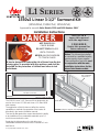
1550v2 Linear 3-1/2” Surround Kit
Installation Instructions
Approved for use with Valor Models 1500 and 1600 Heaters ONLY
The 1550v2 Linear 3-1/2” Surround Kit is designed to be
used on the Linear L1 1500 and Linear L1 2-sided 1600
Valor heaters.
The application of this kit does not affect the venting
capabilities or method of preparation of the heater as
described in the heater installation manual.
This trim fi ts fl at against the cement board with the ability
to tuck additional non-combustible materials up to 1/2
inch thickness behind the trim.
Replacing the side panels on the trim allow non-
combustible material thickness to be increased to 1 inch.
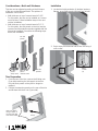
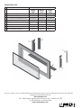
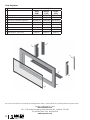
Overview (Fireplace engines sold separately)
Trim size
Non-combustible
cement board
Barrier screen
LH Trim panel
RH Trim panel
LH Side door
RH Side
door
Trim
Plinth
21-1/4” (540 mm)
46-3/16” (1173 mm)
Thickness 1-3/8” (35 mm)
HOT GLASS WILL
CAUSE BURNS.
DO NOT TOUCH GLASS
UNTIL COOLED.
NEVER ALLOW CHILDREN
TO TOUCH GLASS.
DANGER
!
A barrier designed to reduce the risk of burns from the hot
viewing glass is provided with this appliance and shall be
installed for the protection of children and other at-risk
individuals.
Notes: This kit must be installed
or serviced by a qualifi ed installer,
service agency or gas supplier.
These instructions are to be used
in conjunction with the main
installation instructions for the
above listed heater models.
INSTALLER
Leave this manual
with the appliance.
CONSUMER
Retain this manual for
future reference.

2
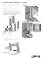
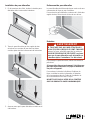
Installation
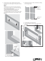
1. Locate trim inside perimeter of ‘window’ aperture
fl anges, press fi rmly against fi nished face of wall.
2. Select a pre punched hole and secure trim using 4
no 8 screws.
Note: The metal
fl ange is wider at
the top of the trim
than at the bottom
Top
Bottom
fi xing
screws
(4)
LH side
panels
RH side
pannels
0 - 1/2”,
panels
‘deep’ notch
1/2” - 1”,
panels
‘shallow’ notch
Considerations—fi nish wall thickness
This trim can be adjusted according to the thickness
of the non-combustible wall fi nish. Two options of
installation can be used:
• Wall thickness on top of cement board of 0-1/2”.
For this option, the trim can be installed as it comes
out of the box. Follow installation steps in the next
section Installation.
• Wall thickness on top of cement board of 1/2”-1”.
For this option, the side panels on the trim must be
removed and the extension panels supplied with this
kit must be installed. Proceed to the following steps
before the installation.
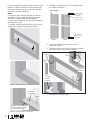
Trim Preparation
1. From the rear of the trim, remove the 6 fi xing nuts
(3 per side) retaining the side panels to the trim.
Recycle these panels as they will no longer be
required.
2. Position the extension panels on the rear of the trim
and fi x them with the 6 nuts (3 per side).

3
3. Position plinth in space between glass and trim,
locate ends onto end support. Ensure plinth is level
with trim.
Notes :
- The opening in the plinth should be oriented as
shown below to allow air to enter while obstructing
any view through the opening.
- Each end of the plinth has a rounded notch
opening to insert the tab of the side doors.
- The bottom edge of the trim is more or less visible
depending of the thickness of the wall fi nish under
the trim.
TOP of door:
this space is
wider
TOP of door:
tab at the rear
Left door
BOTTOM of door:
this space is
narrower
Rear view
Front view
4. Identify left hand door and its orientation according
to the images below.
5. Locate hinge pin into upper hole.
6. Lower door hinge pin into the notch at the end of
the plinth.
7. Repeat for right hand door.
Trim directly on the fi nished cement board
Flange below plinth is
visible when the trim is on
thicker wall fi nish
Trim on 1” thick wall fi nish
Plinth
Opening in
the plinth
Insert tab
here
hinge pin
hinge
pin
hinge
pin
Insert hinge
pin here
Insert hinge
pin here

4
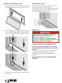
Installation of the barrier screen
1. Hold the screen on the sides and locate the top into
the channel inside the top section of the surround.
2. Grab the fi nger tabs on the bottom of the frame and
lower the screen straight down locating the bottom
hooks into slots hidden just behind surround plate.
3. Verify that the screen is properly hooked to the trim
and secure.
WARNING
DO NOT TOUCH THE BARRIER SCREEN OR
DO NOT TOUCH THE BARRIER SCREEN OR
FIREPLACE WHILE THEY ARE HOT!
FIREPLACE WHILE THEY ARE HOT!
Let the
Let the
fi replace cool fi rst before cleaning it.
fi replace cool fi rst before cleaning it.
FOR SAFETY PURPOSE, ensure the barrier
FOR SAFETY PURPOSE, ensure the barrier
screen is re-installed on the fi replace front after
screen is re-installed on the fi replace front after
maintenance if it has been removed.
maintenance if it has been removed.
WARNING
!
Removing the screen
The barrier screen will need to be removed to access
the fi replace controls or for maintenance.
To remove the screen, hold both fi nger tabs and lift and
tilt the bottom towards you, lower screen to clear the
surround and away from the fi replace.
Maintenance
To clean the fi replace trim, use mild soap and water.
To clean the barrier screen, dust with a soft brush.
If the barrier becomes damaged, the barrier shall
be replaced with the manufacturer’s barrier for this
appliance.
To clean the window and ceramics inside the fi rebox,
consult the Owner’s Information section of the
Installation and Owner’s Manual supplied with the
fi replace.
DO NOT CLEAN THE GLASS WINDOW WITH
AMMONIA!
Finger tab
Front tab

5
Repair Parts List
Description Part Numbers
Black
(LSB)
Bronze
(LSZ)
Nickel
(LSP)
1 LH door assembly 4002957AZ 4002957AZ 4002957AZ
2 RH door assembly 4002959AZ 4002959AZ 4002959AZ
3 LH side panel (extended version) 4003090AZ 4003090AZ 4003090AZ
4 RH side panel (extended version 4003091AZ 4003091AZ 4003091AZ
5 Plinth 4002929AZ 4002929AZ 4002929AZ
6 Trim frame 4005362 4005362BR 4005362P
7 Barrier screen 4004215 4004215 4004215
#8 x 3/8 black screws (4) 100A757 100A757 100A757
1
2
3
4
5
6
7
Designed and Manufactured by / for
Miles Industries Ltd.
190 – 2255 Dollarton Highway, North Vancouver, B.C., CANADA V7H 3B1
Tel. 604-984-3496 Fax 604-984-0246
www.valorfi replaces.com
Because our policy is one of constant development and improvement, details may vary slightly from those given in this publication.

6
Bordure Linear 3-1/2” 1550v2
Directives d’installation
Homologuée pour utilisation avec les foyers Valor 1500 et 1600 SEULEMENT
SÉRIE L1
© Miles Industries Ltd., 2015.Tous droits réservés.
LE PREMIER
FOYER À GAZ RADIANT
MC
®
VITRE CHAUDE - RISQUE
DE BRÛLURES.
NE TOUCHEZ PAS UNE
VITRE NON REFROIDIE.
NE LAISSEZ JAMAIS UN
ENFANT TOUCHER LA VITRE.
L’écran pare-étincelles fourni avec ce foyer réduit le risque
de brûlure en cas de contact accidentel avec la vitre chaude
et doit être installé pour la protection des enfants et des
personnes à risques.
DANGER
!
Notes : Ce kit doit être installé ou
réparé par un installateur quali-
fi é, une agence de service cer-
tifi ée ou un fournisseur de gaz.
Ces directives doivent être
utilisées conjointement avec
les directives d’installation du
foyer Valor indiqué ci-dessus.
INSTALLATEUR
Laissez cette notice
avec l’appareil.
CONSOMMATEUR
Conservez cette notice pour
consultation ultérieure.
(1550LFBv2, 1550LFPv2, 1550LFZv2)
La Bordure Linear 3-1/2” 1550v2 est conçue pour installer sur
les foyers Valor Linear L1 1500 et L1 à 2 côtés 1600.
L’installation de ce kit n’affecte pas l’évacuation ou méthode
de préparation du foyer 1500 tel que décrit dans le guide
d’installation du foyer.
Cette bordure peut être installée directement sur le panneau
de béton incombustible ou sur un matériau de fi nition
incombustible jusqu’à 1/2 pouce (13 mm) d’épaisseur
couvrant le panneau de béton. L’épaisseur peut-être
augmentée à 1 pouce (26 mm) en remplaçant les panneaux
des côtés de la bordure (inclus).
Concept (Foyers vendus séparément)
Dimensions de la bordure
Panneau de béton
incombustible
Pare-étincelles
Panneau gauche
Panneau droit
Porte gauche
Porte
droite
Bordure
Plinthe
21-1/4” (540 mm)
46-3/16” (1173 mm)
Épaisseur 1-3/8” (35 mm)

7
Note : le rebord de
métal au haut de la
bordure et plus large
que celui du bas
Haut
Bas
Installation
1. Placez la bordure dans le périmètre de l’ouverture
du foyer et poussez-la fermement contre la surface
du mur fi ni.
2. Sélectionnez un trou de fi xation et fi xez la bordure
au foyer à l’aide de 4 vis n
o
8.
Vis de
fi xation (4)
Panneaux
gauches
Panneaux
droits
0 - 1/2” (13 mm),
panneaux à découpe
plus profonde
1/2” - 1” (13-26mm),
panneaux à découpe
plus étroite
Considérations—épaisseur de la fi nition du mur
Cette bordure est ajustable selon l’épaisseur du mur in-
combustible fi ni. Deux options d’installation sont offertes :
• Épaisseur du mur par-dessus le panneau de béton
de 0 à 1/2 pouce (0-13 mm). Pour cette option, la
bordure peut être installée sans qu’il soit nécessaire
de la modifi er. Passez directement à la section
Installation.
• Épaisseur du mur par-dessus le panneau de béton
de 1/2 pouce à 1 pouce (13-26 mm). Pour cette
option, les panneaux de côtés de la bordure doivent
être remplacés par les panneaux d’extension fournis
avec le kit. Suivez les étapes ci-dessous.
Préparation de la bordure
1. De l’arrière de la bordure, enlevez les 6 écrous (3
de chaque côté) retenant les deux panneaux des
côtés. Recyclez ces panneaux car ils ne sont plus
nécessaires.
2. Placez les panneaux d’extension sur la bordure
tel qu’indiqué et fi xez-les avec les 6 écrous (3 de
chaque côté).

8
3. Placez la plinthe dans l’espace entre la fenêtre et la
bordure. La plinthe repose sur le rebord au bas de
la bordure; assurez-vous que le bord de la plinthe
est égal au bord de la bordure.
Notes :
- L’ouverture dans la plinthe doit être orientée tel
qu’indiqué ci-dessous afi n de permettre l’entrée
d’air tout en cachant l’intérieur de l’appareil.
- L’espace arrondi dans le coin permet l’installation
des portes des côtés.
- Le rebord au bas de la bordure est plus ou moins
visible selon l’épaisseur de la fi nition du mur.
HAUT de porte :
cet espace est
plus large
HAUT de porte :
onglet à l’arrière
Porte gauche
BAS de porte :
cet espace est
plus étroit
Arrière
Avant
4. Identifi ez la porte gauche et son orientation selon
les images ci-dessous.
5. Insérez la cheville dans le trou du haut de
l’ouverture du foyer.
6. Poussez la porte vers le haut et insérez la cheville
du bas dans le trou au bout de la plinthe.
7. Répétez avec la porte droite.
Bordure sur panneau de béton fi ni
Rebord de métal de la bordure
est visible quand la bordure
est sur un fi ni plus épais
Bordure sur fi nition de 1 po d’épaisseur
Plinthe
Ouverture
de la plinthe
Insérez la
cheville ici
cheville
cheville
cheville
Insérez la
cheville ici
Insérez la
cheville ici

9
Installation du pare-étincelles
1. En le tenant par les côtés, insérez le haut du pare-
étincelles dans la rainure de la bordure.
2. Tenez le pare-étincelles par les onglets du bas
et insérez les crochets du bas dans les fentes
cachées juste derrière la face avant de la bordure.
3. Assurez-vous que le pare-étincelles est bien ancré
à la bordure.
Enlèvement du pare-étincelles
Le pare-étincelles doit être enlevé pour avoir accès aux
commandes du foyer ou pour l’entretien.
Pour enlever le pare-étincelles, soulevez-le à l’aide des
onglets du bas, décrochez-le et tirez-le vers le bas.
Entretien
Pour nettoyer le pare-étincelles, utilisez une brosse à
poils doux.
Si le pare-étincelles est endommagé, il doit être rem-
placé par le pare-étincelles conçu par le manufactu-
rier pour cet appareil.
Pour nettoyer la vitre de la fenêtre et l’intérieur du
foyer, consultez la section Information à l’intention
du consommateur dans le Guide de l’installation et
du consommateur fourni avec le foyer.
NE NETTOYEZ PAS LA VITRE DE LA FENÊTRE
AVEC UN PRODUIT À BASE D’AMMONIAQUE!
Crochet
Onglet
AVERTISSEMENT
NE TOUCHEZ PAS AU
NE TOUCHEZ PAS AU
PARE-ÉTINCELLES
PARE-ÉTINCELLES
OU AU FOYER LORSQU’ILS SONT CHAUDS!
OU AU FOYER LORSQU’ILS SONT CHAUDS!
Laissez le foyer refroidir avant de le nettoyer.
Laissez le foyer refroidir avant de le nettoyer.
POUR DES RAISONS DE SÉCURITÉ, assurez-
POUR DES RAISONS DE SÉCURITÉ, assurez-
vous que le pare-étincelles soit réinstallé sur
vous que le pare-étincelles soit réinstallé sur
la bordure après l’entretien s’il a été enlevé.
la bordure après l’entretien s’il a été enlevé.
AVERTISSEMENT
!

10
Description Numéros de pièces
Noire
(LSB)
Bronze
(LSZ)
Nickel
(LSP)
1 Porte gauche 4002957AZ 4002957AZ 4002957AZ
2 Porte droite 4002959AZ 4002959AZ 4002959AZ
3 Panneau d’extension gauche 4003090AZ 4003090AZ 4003090AZ
4 Panneau d’extension droit 4003091AZ 4003091AZ 4003091AZ
5 Plinthe 4002929AZ 4002929AZ 4002929AZ
6 Bordure 4005362 4005362BR 4005362P
7 Pare-étincelles 4004215 4004215 4004215
Vis noires n
o
8 x 3/8 (4) 100A757 100A757 100A757
Liste de pièces
1
2
3
4
5
6
7
Conçue et fabriquée par / pour
Miles Industries Ltd.
190 – 2255 Dollarton Highway, North Vancouver, BC, CANADA V7H 3B1
Tél. 604-984-3496 Téléc. 604-984-0246
www.foyervalor.com
Parce que nous favorisons une politique de développement continu, certains détails de la présente publication peuvent varier.
-
 1
1
-
 2
2
-
 3
3
-
 4
4
-
 5
5
-
 6
6
-
 7
7
-
 8
8
-
 9
9
-
 10
10


Miles Industries 1550LFBv2 Le manuel du propriétaire
- Catégorie
- Cheminées
- Taper
- Le manuel du propriétaire
- Ce manuel convient également à
dans d''autres langues
Autres documents
-
Valor 1750LF v2 Le manuel du propriétaire
-
-
-
-
-
-
-
-
-