Panasonic Projection Television PT 50DL54 Manuel utilisateur
- Catégorie
- Équipement musical supplémentaire
- Taper
- Manuel utilisateur
Ce manuel convient également à

HDTV DLP™ Projection Monitor
Operating Instructions
Monitor de proyección de HDTV DLP™
Instrucciones de Operación
Téléprojecteur haute définition DLP™
Manuel d’utilisation
TQB2AA0509 40514
PRINTED IN USA
IMPRESO EN EE.UU
IMPRIMÉ AUX ÉTATS-UNIS

ENGLISH
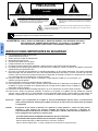
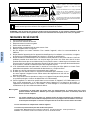
The exclamation point within a triangle
is intended to tell the user that
important operating and servicing
instructions are in the papers with the
appliance.
The lightning flash with arrow head
within a triangle is intended to tell the
user that parts inside the product
constitute a risk of electric shock to
persons.
RISK OF ELECTRIC SHOCK
DO NOT OPEN
WARNING
WARNING: TO REDUCE THE RISK OF FIRE OR ELECTRIC SHOCK, DO NOT EXPOSE THIS
APPARATUS TO RAIN OR MOISTURE. DO NOT PLACE ANY OBJECTS FILLED WITH
LIQUIDS, SUCH AS VASES, ON THIS APPARATUS.
The Class II insulation symbol (square within a square) indicates that this product has been evaluated
and tested to comply with Class II insulation requirements.
IMPORTANT SAFETY INSTRUCTIONS
1. Read these instructions.
2. Keep these instructions.
3. Heed all warnings.
4. Follow all instructions.
5. Do not use this apparatus near water.
6. Clean only with dry cloth.
7. Do not block any ventilation openings. Install in accordance with the manufacturer’s instructions.
8. Do not install near any heat sources such as radiators, heat registers, stoves, or other apparatus (including
amplifiers) that produce heat.
9. Do not defeat the safety purpose of the polarized or grounding type plug. A polarized plug has two blades with
one wider than the other. A grounding type plug has two blades and a third grounding prong. The wide blade
or the third prong are provided for your safety. If the provided plug does not fit into your outlet, consult an elec-
trician for replacement of the obsolete outlet.
10. Protect the power cord from being walked on or pinched particularly at plugs, convenience
receptacles, and the point where they exit from the apparatus.
11. Only use attachments/accessories specified by the manufacturer.
12. Use only with the cart, stand, tripod, bracket or table specified by the manufacturer, or sold
with the apparatus. When a cart is used, use caution when moving the cart/apparatus combi-
nation to avoid injury from tip-over.
13. Unplug this apparatus during lightning storms or when unused for long periods of time.
14. Refer all servicing to qualified service personnel. Servicing is required when the apparatus has been dam-
aged in any way, such as power-supply cord or plug is damaged, liquid has been spilled or objects have fallen
into the apparatus, the apparatus has been exposed to rain or moisture, does not operate normally, or has
been dropped.
WARNING: TO REDUCE THE RISK OF ELECTRIC SHOCK DO NOT REMOVE
COVER OR BACK. NO USER-SERVICEABLE PARTS INSIDE. REFER SERVICING
TO QUALIFIED SERVICE PERSONNEL.
Read these instructions completely before operating television.
Contents are subject to change without notice or obligation.
Copyright 2004 by Matsushita Electric Corporation of America. All rights reserved.
Unauthorized copying and distribution is a violation of law.
The pictorial representation of a hot
surface within a triangle is intended to
tell the user that parts inside the
product are a risk of burns to persons.
WARNING: Because the temperature of the lamp unit remains hot for a time after the TV is turned off, touching it may
cause burns. Please allow the lamp to cool (for at least 1 hour) before handling or replacing the lamp unit.
CAUTION: Slots and openings in the cabinet and the back or bottom are provided for ventilation to ensure
reliable operation of the projection TV and protect it from overheating. These openings must not be
blocked or covered. There should be at least 4 inches between the cabinet and any wall.

IMPORTANT INFORMATION
1 z
ENGLISH
Important Information
FCC CAUTION: ANY CHANGES OR MODIFICATIONS TO THIS PTV RECEIVER NOT EXPRESSLY
APPROVED BY MATSUSHITA ELECTRIC CORPORATION OF AMERICA COULD CAUSE
HARMFUL INTERFERENCE, WHICH WOULD VOID THE USER’S AUTHORITY TO
OPERATE THIS EQUIPMENT.
FOR PRODUCT RECYCLING
THIS PRODUCT UTILIZES A HIGH PRESSURE MERCURY DISCHARGE LAMP THAT
CONTAINS MERCURY AND OTHER COMPONENTS THAT CONTAIN LEAD.
DISPOSAL OF THESE MATERIALS MAY BE REGULATED IN YOUR COMMUNITY
DUE TO ENVIRONMENTAL CONSIDERATIONS. FOR DISPOSAL OR RECYCLING
INFORMATION PLEASE CONTACT YOUR LOCAL AUTHORITIES, OR THE
ELECTRONICS INDUSTRIES ALLIANCE: <HTTP://WWW.EIAE.ORG.>
ENVIRONMENTAL NOTICE:
Manufactured under license from BBE Sound, Inc.
Licensed by BBE Sound, Inc. under USP4638258, 5510752 and 5736897.
BBE and BBE symbol are registered trademarks of BBE Sound, Inc.
BBE ViVA HD3D (High Definition 3D) Sound provides musically accurate natural 3D
image with Hi-Fi sound. The clarity of the sound is improved by BBE while the width,
depth and height of sound image are expanded by BBE’s proprietary 3D sound process.
BBE ViVA HD3D Sound is compatible with all TV programs including news, music,
dramas, movies, sports and electronic games.
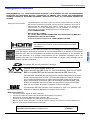
HDMI, the HDMI logo and High Definition Multimedia Interface are
trademarks or registered trademarks of HDMI Licensing LLC.
Trademarks
• DLP™ is a registered trademark of Texas Instruments.
• VGA is a trademark of International Business Machines Corporation.
• Macintosh is a registered trademark of Apple Computer, USA.
• S-VGA is a registered trademark of the Video Electronics Standards Association.
• Even if no special notation has been made of company or product trademarks, these trademarks have been fully
respected.
: SD Logo is a trademark.
BBE High Definition Sound restores clarity and presence for better speech
intelligibility and music realism.
High Definition Sound
For assistance, please call: 1-888-843-9788
or send e-mail to: [email protected]
or visit us at www.panasonic.com
(U.S.A.)
For assistance, please call: 787-750-4300
or visit us at www.panasonic.com
(Puerto Rico)
For assistance, please call: 905-624-5505
or visit us at www.panasonic.ca
(Canada)
FOR LAMP RECYCLING
Hg - LAMP CONTAINS MERCURY, MANAGE IN ACCORD WITH DISPOSAL LAWS.
SEE: WWW.LAMPRECYCLE.ORG OR 1-888-843-9788
The Energy Star label, a symbol for energy efficiency, was created by the U.S. Environmental
Protection Agency (EPA) and the U.S. Department of Energy (DOE) to help customers identify
products that can save them money and protect the environment by saving energy. Energy
Star compliant products generally consume less energy than similar standard products.

2 z
IMPORTANT INFORMATION
ENGLISH
FCC Declaration of Conformity
Responsible Party:
Matsushita Electric Corporation of America
One Panasonic Way, Secaucus, NJ 07094
Contact Source:
Panasonic Consumer Electronics Company
1-800-211-PANA (7262)
E-mail: http://www.panasonic.com/contactinfo
FCC Information
This equipment has been tested and found to comply with
the limit for a Class B Digital Device in accordance with the
specifications in Part 15 of the FCC Rules. The limits are
designed to provide reasonable protection against radio
and television interference in a residential installation. This
equipment generates, uses and can radiate radio
frequency energy and, if not installed and used in
accordance with the instructions, may cause harmful
interference to radio communications. However, there is no
guarantee that interference will not occur in a particular
installation.
If this equipment does cause interference to radio or
television reception (which you can determine by turning
the equipment off and on), try to correct the interference by
one or more of the following measures.
• Reorient or relocate the receiving antenna.
• Increase the separation between the equipment and the
receiver.
• Connect the equipment into an outlet on a circuit
different from that which the receiver is connected.
• Consult the dealer or an experienced radio/TV
technician for help.
Industry Canada Information
This Class B digital apparatus complies with Canadian
ICES-003.
Important Information when using the
Projection TV
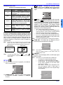
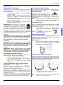
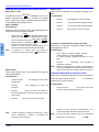
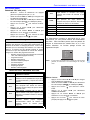
Reflection of external light
The DLP™ Projection Television should be installed so that
external light shining on the screen is minimized. If sunlight
or any bright light shines directly onto the screen, some
part of the screen may appear white, whether the
Projection Television is on or off. This is not a defect.
Cooling Fan Information
This Projection Television has a fan for cooling the built-in
lamp. After turning the set off, the fan will continue cooling
the lamp for about one minute.
Note: During the lamp cooling process you may hear sounds from the
fan. This is not a defect, the sound will stop after one minute.
If the set is turned back on before the fan stops or the lamp
is not cool enough, it may take a while to display a normal
picture. This is not a defect.
Screen may appear white from
reflection of external light.

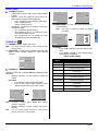
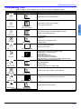
TABLE OF CONTENTS
3 z
ENGLISH
Table of Contents
Important Information ..................................... 1
FCC Declaration of Conformity................................... 2
FCC Information ......................................................... 2
Reflection of External Light......................................... 2
Cooling Fan Information............................................. 2
Customer Record........................................................ 4
Care and Cleaning...................................................... 4
Specifications.............................................................. 4
Feature Chart.............................................................. 4
Installation........................................................ 5
Television Location..................................................... 5
Optional Cable Connections....................................... 5
AC Power Supply Cord............................................... 5
Cable / Antenna Connection....................................... 5
Safety Precautions...................................................... 5
Affixing Projection Television to a Wall .................. 5
Viewing Position ......................................................... 5
Remote Control Battery Installation............................ 6
Replacing the lamp unit .................................. 6
Lamp Unit Replacement Period.................................. 6
Important Points to Keep in Mind................................ 6
Cautions for Lamp Unit Replacement......................... 6
Procedures to Turn Power Off.................................... 6
Power On/Off.................................................... 7
Connecting the Plug to the Wall ................................. 7
Turning the Power On and Off.................................... 7
Power Indicator Chart................................................. 7
Initial Set Up Menu........................................... 7
Front , Rear and Right Side View of the
Projection Television.................................... 8
Optional Equipment Connections.................. 9
RGB Input Connection................................................ 9
Analog RGB Signals that can be Input....................... 9
VCR........................................................................... 10
Cable Box.................................................................. 10
VCR and Cable Box................................................... 10
Amplifier Connection................................................. 11
Digital TV - Set-Top Box (DTV-STB) or DVD Players 11
Program Out Connection........................................... 11
HDMI (High Definition Multimedia Interface) Input
Connection............................................................. 12
Special Features........................................................ 13
ASPECT Button.......................................................... 13
BBE Button................................................................. 13
SAP Button................................................................. 13
Split Screen Operation............................................... 13
Split Screen Operation with Cable Box...................... 13
Split Screen Operational Buttons............................... 14
Split CTRL Button................................................... 14
TV/Video Button...................................................... 14
Search Button......................................................... 14
Freeze Button......................................................... 14
Main Picture Freeze Feature.................................. 14
Direct Video Input Selection....................................... 14
Remote Control Operation ............................15
Programming the Remote.......................................... 16
Programming Without a Code.................................... 16
Component Codes..................................................... 16
Operating Components with Remote Control............. 19
Basic Menu Navigation............................................... 21
Icon Menus Operation................................................ 22
Picture..................................................................... 22
Audio....................................................................... 22
Channels................................................................. 23
Timer....................................................................... 24
Lock......................................................................... 24
Set Up ..................................................................... 27
Photo Viewer Operation ............................... 29
Troubleshooting Chart ................................. 31
Index............................................................... 33
Note: The warranty and service center information is located in the back of this manual.

4 z
CONGRATULATIONS
ENGLISH
Congratulations
Your new Projection Television features state-of-the-art
technology for high quality picture and sound with complete
audio/video connections for your home theater system.
Your Projection Television is designed to give you many
years of enjoyment. It was thoroughly tested and tuned at
the factory for best performance.
Customer Record
The model and serial number of this product are located on
the back of the Projection Television. You should note the
model and serial number in the space provided and retain as a
permanent record of your purchase. This will aid in
identification in the event of theft or loss. Product registration
for U.S. customers is available at: www.prodreg.com/
panasonic.
Model
Number
Serial
Number
Care and Cleaning
Screen (Turn Projection Television Off)
To ensure continued excellent performance by this product,
periodic cleaning is recommended.
• Dust will accumulate on the picture screen. Please wipe
with a soft cloth from time to time.
Warning: Do not spray any type of cleaning fluid directly on the
screen.
Cabinet and Remote Control
• For cabinets and remote control, use a soft cloth
dampened with water or a mild detergent solution. Avoid
excessive moisture and wipe dry.
• Do not use benzene, thinner or other petroleum based
products.
• For cabinets, do not bring into contact with insecticide or
other volatile substances.
• Do not allow the unit to come into contact for extended
periods with rubber or vinyl products.
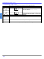
Specifications
Specifications are subject to change without notice or
obligation.
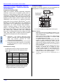
Feature Chart
Power Source
PT-60DL54 (2.4A)
PT-50DL54 (2.4A)
PT-50DL54X (2.4A)
120 V AC, 60Hz
127 V AC, 60Hz
Channel Capability - 181 VHF-12; UHF-56; Cable-113
Video Input Jacks 1Vp-p, 75 Ohm, Phono Jack Type
Audio Input Jacks 500mV RMS 47K Ohm
Video out jack 1Vp-p, 75 Ohm, Phono Jack Type
Audio Output Jacks 0-2.0V RMS 4.7K Ohm
HDMI Input jack Type A
RGB Inputs D-Sub 15pin
Components Input (Y / P
B
/ P
R
)
75 Ohm, Phono Jack Type
S-Video Input Jacks S-Video (Y-C) Connector
Projection Lamp
100 W HID (High Intensity Discharge)
Lamp (recommended replacement
period approximately 10,000 hours)
MODELS
PT-50DL54
PT-50DL54X
PT-60DL54
FEATURES
MENU
LANGUAGE
ENG/SPAN/FR
• • •
2 TUNER SPLIT
SCREEN
• • •
CLOSED
CAPTIONING
• • •
V-CHIP
CAPABILITY
• • •
DIGITAL SCAN
RATE
720p 720p
720p
NTSC
LINE-DOUBLER
480p 480p 480p
RESOLUTION
1280 X 720 1280 X 720
1280 X 720
RGB
RESOLUTION
VGA (640 X 480)
SVGA (800 X 600)
XGA (1024 X 768)
VGA (640 X 480)
SVGA (800 X 600)
XGA (1024 X 768)
VGA (640 X 480)
SVGA (800 X 600)
XGA (1024 X 768)
VIDEO NORM
• • •
AUDIO NORM
• • •
STEREO
• • •
AI SOUND
• • •
BASS/TREBLE/
BALANCE/
• • •
SURROUND
SOUND
• • •
BBE/VIVA SOUND
• • •
A/V IN
(REAR/SIDE)
3
(2/1)
3
(2/1)
3
(2/1)
AUDIO OUT
• • •
RGB INPUT
2 2 2
HDMI/HDCP
INPUT
• • •
S-VHS INPUT
(REAR/SIDE)
3
(2/1)
3
(2/1)
3
(2/1)
COMPONENT
INPUT
3 3 3

INSTALLATION
5 z
ENGLISH
Installation
Television Location
This unit can be used as part of an entertainment center.
Consult your dealer for available options.
• Avoid excessive sunlight or bright lights, including
reflections.
• Keep away from excessive heat or moisture. Inadequate
ventilation may cause internal component failure.
• Fluorescent lighting may reduce remote control
transmitting range.
• Keep away from magnetic equipment, including motors,
fans and external speakers.
WARNING: Use this Projection Television receiver
only with the cart, stand, tripod, bracket, or table
specified by the manufacturer, or sold with the
apparatus. When a cart is used, use caution when
moving the cart/apparatus combination to avoid injury
from tip-over. In order to avoid injury to children, never place your
Projection Television receiver on a piece of furniture that is
capable of being tilted by a child leaning on it, pulling on it,
standing on it, or climbing on it. A falling Projection Television can
cause serious injury or even death.
PT-50DL54:
CAUTION: This Projection receiver for use only with
PANASONIC TY-50DL54K stand. Use with other carts
(or stands) is capable of resulting in instability causing
possible injury.
PT-50DL54X:
CAUTION: This Projection receiver for use only with
PANASONIC TY-50DL54K stand. Use with other carts
(or stands) is capable of resulting in instability causing
possible injury.
PT-60DL54:
CAUTION: This Projection receiver for use only with
PANASONIC TY-60DL54K stand. Use with other carts
(or stands) is capable of resulting in instability causing
possible injury.
Optional Cable Connections
Shielded audio and video cables should be used between
components. For best results:
• Use 75-ohm coaxial shielded cables.
• Use appropriate input and output connectors that match
your component connectors.
• Avoid long cables to minimize interference.
AC Power Supply Cord
CAUTION: TO PREVENT ELECTRIC SHOCK,
MATCH WIDE BLADE OF PLUG TO WIDE SLOT
OF AC OUTLET AND FULLY INSERT. DO NOT
USE A PLUG WITH A RECEPTACLE OR OTHER
OUTLET UNLESS THE BLADE CAN BE FULLY INSERTED TO
PREVENT BLADE EXPOSURE.
PROTECT POWER CORDS FROM BEING WALKED ON, ROLLED
OVER, CRIMPED, BENT, OR PINCHED, PARTICULARLY AT PLUGS,
CONVENIENCE RECEPTACLES, AND THE POINT WHERE THEY EXIT
FROM THE APPARATUS.
Cable / Antenna Connection
For proper reception, either a cable or antenna connection
is required.
Cable Connection
Connect the cable supplied by your local
cablecompany. Tighten with fingers only.
Use of any tool (e.g. pliers) for tightening
may result in tuner damage.
Note: A cable converter box may be
required for proper reception.
Check with your local cable
company for compatibility requirements.
Antenna Connection
For proper reception of VHF/UHF channels, an external antenna
is required. For best reception an outdoor antenna is
recommended.
• Connect home antenna to ANT
connection on back of television.
Note: Cable Mode is preset at the
factory.
Safety Precautions
Please take safety precautions to
prevent the unit from falling over. The unit may fall over
during earthquakes, or if someone stands on or shakes the
projection TV.
Procedure
• Use a strong rope or a chain (not included) to fasten the
projection TV firmly to a strong support such as a wall or
pillar.
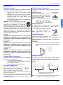
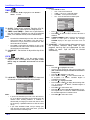
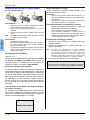
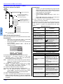
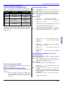
Viewing Position
To optimize your viewing comfort, please follow the viewing
guidelines shown in the diagrams below. If viewing for an
extended period of time, sit as far back from the screen as
possible.
Note: If you view the Projection Television at a short distance
for a long time, your eyes may become fatigued.
Polarized plug
75 Ohm VHF/UHF
on back of PTV
Incoming Cable from
Cable Company
Incoming Cable from
Home Antenna
Viewing distance for 50” models is at least
6 feet and for 60” is at least 7 feet.
70
o
70
o
30
o
30
o

6 z
INSTALLATION
ENGLISH
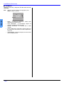
Remote Control Battery Installation
Requires two AA batteries (supplied).
Procedure
1. Remove battery cover by pushing in on the catch while
lifting the cover up.
2. Install batteries by matching (+) and (-) polarity signs in
the compartment.
3. Re-insert the cover and press down the cover until it
snaps shut.
Note: Incorrect installation can cause battery leakage and
corrosion that will damage the Remote Control.
Precautions
• Replace batteries in pairs.
• Do not mix battery types (zinc carbon with alkaline).
• Do not recharge, heat, short-circuit, disassemble, or
burn batteries.
Replacing the lamp unit
(For USA and Canada only)
(USA only)
The lamp unit is sold separately Lamp unit Part No. :
TY-LA2004. To purchase a replacement, call the
Panasonic accessory department, toll free at:
1-800-332-5368.
(Canada only)
For product operation and information assistance, please
contact your Dealer or our Customer Care Centre at:
(905) 624-5505.
Lamp unit replacement period
The lamp unit for the projection TV should be replaced after
approximately 10,000 hours of use in the normal usage
mode. Due to the characteristics and use conditions of
individual lamps, the lamp may cease to light before the
stated lamp life. Influences of frequent lighting, continuous
light use for over 24 hours, the number of times lit, the
length of time between lightings, etc. may shorten lamp life.
Because of this, having a replacement lamp on hand is
recommended.
A warning will display after 10,000 hours of use. When the
power is turned on after 10,000 hours of continued use,
REPLACE LAMP will be displayed for approximately 1 min.
A warning message to urge the replacement of the lamp
will be displayed in red at the center of the screen.
Important Points to keep in mind
When replacing the lamp unit, pay attention to the following
points.
Warning:
• The lamp unit is hot during operation and touching it
immediately after use may cause burns.
• Please allow the lamp to cool (for at least 1 hour)
before handling or replacing the lamp unit.
Cautions for Lamp Unit Replacement:
• Handle the old lamp unit carefully. If mishandled, it may
explode.
• Wear gloves when replacing the lamp unit.
• If replacing the lamp unit becomes necessary during the
operation of the TV, follow the procedure below to turn
off the power and wait until the lamp unit cools
completely.
Procedures to turn Power Off
1. Press the POWER button to turn off the power.
2. Wait for about
one minute until the cooling fan stops.
Note: The lamp cooling fan will continue to operate for about
one minute after turning off the power. Do not unplug the
power cord from the outlet until the fan has stopped.
Avoid interrupting the power line such as by using circuit
breakers or switchable power strips.
3. Unplug the power cord from the outlet.
+
-
+
-
+
+
-
+
-
1
2 3
REPLACE LAMP
For USA and Canada only.
Refer to the instructions enclosed with the lamp unit
(Part No. TY-LA2004) when replacing the lamp.

POWER ON/OFF
7 z
ENGLISH
POWER ON/OFF
Connecting the Plug to the Wall Outlet
The projection TV must first be plugged into an AC outlet.
The projection TV will then be in standby mode.
Turning the Power ON and OFF
Always be sure to follow the procedure below to turn the
Projection Television power ON and OFF.
The lamp cooling fan will continue to operate for
approximately one minute after the power is turned off by
the remote control.
After the cooling fan has stopped, the power indicator will
not illuminate (Stand-by mode). If you wish to turn the
power ON while the cooling fan is operating, press the
power button. The power indicator on the Projection
Television will then flash in green, and the projection
Projection Television will turn ON as soon as the cooling
fan stops. Always use the remote control or power button
on the Projection Television to turn the power OFF.
Caution: Do not turn off by external power strip or by
pulling plug. Do not open any circuit breakers
while the cooling fan is still operating.
Procedure for turning ON
• Press the Power button to turn the projection TV on, from
Stand-by mode.
Note: The Power Indicator will blink green for
approximately 10 seconds, and then become
green.
Procedure for turning OFF
• Press the Power button to turn the projection TV to
Stand-by mode.
Notes:
• The Power Indicator will become orange for
approximately 10 seconds.
• The Power Indicator will blink orange for approximately 60
seconds.
• The Power Indicator light will go out.
Note: The Projection Television will consume a small amount
of power as long as the power cord is connected to a
power outlet.
Power Indicator Chart
Initial Set Up Menu
For your convenience, the Initial Set Up menu will be
displayed on screen when the set is turned on for the first
time. If needed, follow the menus and procedures for
setting up the features.
IDIOMA/LANGUE
To change menu language to ENGLISH, SPANISH or
FRENCH.
Procedure
• Press VOL X to select English, Spanish or French.
MODE
To select TV (antenna) or CABLE mode depending on the
signal source.
Procedure
• Press VOL X to select TV or CABLE.
AUTO PROGRAM
To automatically program all channels received through the
RF input.
Procedure
• Press VOL X to start Auto Programming.
LED ACTION
Not illuminated Stand–by
Green Power – ON
Green blink
Power – ON
(approximately 10 seconds after)
Orange
Power – OFF (Blinking mode)
(approximately 10 seconds after)
Orange blink
Power – OFF (Cooling mode)
(approximately 40 seconds after)
INITIAL SET UP
IDIOMA/LANGUE
MODE
AUTO PROGRAM
ENGLISH
CABLE
PRESS MENU TO EXIT
FIRST PLEASE
CONNECT THE ANTENNA
INITIAL SET UP
IDIOMA/LANGUE
MODE
AUTO PROGRAM
ENGLISH
CABLE
PRESS MENU TO EXIT
FIRST PLEASE
CONNECT THE ANTENNA
INITIAL SET UP
IDIOMA/LANGUE
MODE
AUTO PROGRAM
ENGLISH
CABLE
PRESS MENU TO EXIT
FIRST PLEASE
CONNECT THE ANTENNA

8 z
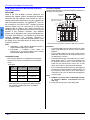
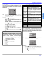
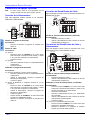
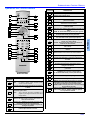
FRONT, REAR AND RIGHT SIDE VIEW OF THE PROJECTION TELEVISION
ENGLISH
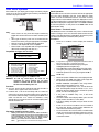
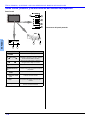
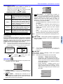
Front, Rear and Right side View of the Projection Television
Front Panel
Right Side Panel
Rear Panel Jacks
Feature Description
POWER
Toggles power OFF/ON
WVOL and VOLX
Decrease or increase volume, navigate
left/right in menu, adjust selected feature
in menu.
TCH and CHS
Tune to lower or higher channels,
navigate up/down in menus.
TV/VIDEO
Change input source
ON/OFF Indicator
The ON/OFF indicator LED (green) will
be lit when Projection Television is on.
DOOR
Pull up here to access SD and PC slots.
SD and PC Slots
Use to insert and remove cards for Photo
Viewer feature.
Temp
This indicator lights up when there is an
abnormal temperature in the unit.
Lamp
This indicator lights up when there is a
malfunction with the lamp unit.
1
POWER
VOL
CH
TV/VIDEO
2
3
4
7 6
5
Open
Temp
Lamp
98
1
2
3
4
5

OPTIONAL EQUIPMENT CONNECTIONS
9 z
ENGLISH
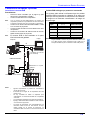
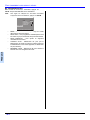
Optional Equipment Connections
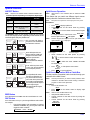
RGB Input Connection
Procedure
• Press the TV/VIDEO button (refer to page 14) to select
RGB 1 or RGB 2 input.
• Connect a RGB cable to Computer or Laptop RGB
output.
Note: If no RGB signal is displayed after connecting laptop,
please refer to laptop manual for procedure on how to
switch the output signal.
• Connect the other end of the RGB cable to RGB IN 1 or
side RGB IN 2 on Projection Television.
• Connect the audio cable to Computer or Laptop AUDIO
OUT.
• Connect the other end of the audio cable to AUDIO IN on
Projection Television.
Note: RGB 2 input is located on lower right side of cabinet.
Notes:
• Some PC models cannot be connected to the Projection
Television.
• The PC display size will be 4:2:2 format.
• There is no need to use an adapter for computers with PC
/ AT compatible D-SUB 15P terminal.
• The computer shown is for illustrative purposes only.
• Additional equipment and cables shown are not supplied
with this Projection Television.
• The picture will become dark if a RGB signal with a
vertical scanning frequency of 62 Hz is input. To obtain
the optimum picture quality with the Projection Television,
a vertical scanning frequency of 60 Hz is recommended.
Analog RGB signals that can be input
The table below lists the different types of analog RGB
signals that can be input. If a signal which differs greatly
from any of the types listed below is input, the picture
image may not be displayed correctly, or a black
background may be displayed.
Note: The number of dots for this Projection Television is 800 × 600
for NORMAL display. Number of dots other than 800 × 600 in
the above data, will be converted to 800 × 600 (with the
exception of MAC 16, which will be displayed in 832 × 624
dots).
T T
Y
P
B
P
R
L
R
Y
P
B
P
R
L
R
Y
P
B
P
R
L
R
VIDEO
L
R
AUDIO
L
R
AUDIO
VIDEO
S-VIDEO
IN 1 IN 2 OUT IN 1 IN 2 IN 3
COMPONENT VIDEO INPUT
R-AUDIO IN-L
HDMI
AV IN
RGB 1 IN
AUDIO IN
ANT
Tower box
T
S-VIDEO
VIDEO
AUDIO
L
R
INPUT3
RGB2 IN AUDIO IN
Laptop
Computer
Terminals on back of
Projection Television
Terminals on right side of TV
or
Cables not Included
Conversion adapter
(if necessary)
Display
mode name
No. of dots
(H x V)
Vertical scanning
frequency (Hz)
VGA70 640 X 400 70.1
VGA60 640 X 480 59.9
SVGA60 800 X 600 60.3
XGA60 1024 X 768 60.0

10 z
OPTIONAL EQUIPMENT CONNECTIONS
ENGLISH
VCR Connection
Note: The remote control must be programmed with supplied
codes to operate the optional equipment.
Follow this diagram when connecting your television to a
VCR only.
Viewing a television program
Procedure
• Tune the television to the program you want to view.
Viewing a video
Procedure
Option A
• Press the TV/VIDEO button on the remote control to
select the video input (VIDEO 1, VIDEO 2, etc.)
connected to your VCR.
• Begin the video.
Option B
• Tune the television to Channel 3 or 4, depending on your
VCR.
• Begin the video.
Recording a television program
Procedure
Option A (Recording and viewing the same program)
• Tune the television to Channel 3 or 4, depending on your
VCR.
• Using the VCR, tune to the television program you want
to record.
• Begin recording.
Option B (Recording one program while viewing another
program)
• Press the TV/VIDEO button on the remote control to
select the video input (VIDEO 1, VIDEO 2, etc.)
connected to your VCR.
• Using the VCR, tune to the television program you want
to record.
• Begin recording.
• Press the TV/VIDEO button on the remote control to
switch back to TV mode.
• Tune the television to the program you want to view.
Cable Box Connection
Follow this diagram when connecting your television to a
cable box only.
Viewing a premium (scrambled) cable channel
Procedure
• Tune the television to Channel 3 or 4 depending on cable
box.
• Using the cable box, tune to the premium cable channel
you want to view.
VCR and Cable Box Connection
Follow this diagram when connecting your television to
both a VCR and a cable box.
Viewing a premium (scrambled) cable channel
Procedure
• Tune the television to Channel 3 or 4 depending on cable
box.
• Using the cable box, tune to the premium cable channel
you want to view.
Recording a premium (scrambled) cable channel
Procedure
• Press the TV/VIDEO button on the remote control to
select the video input (VIDEO 1, VIDEO 2, etc.)
connected to your VCR.
• Turn the VCR ON.
• Tune the VCR to Channel 3 or 4, depending on the
switch setting on the back of VCR.
• Using your cable box, tune to the premium cable channel
you want to record.
• Begin recording.
To view a different channel while recording:
• Press the TV/VIDEO button on the remote control to
select TV mode.
• Tune the television to a program (except another
premium cable channel).
ANT IN ANT OUT
VIDEO OUT
AUDIO OUT
L
R
PLAY
STOP
R
E
W
FF
VCR
Y
P
B
P
R
L
R
Y
P
B
P
R
L
R
Y
P
B
P
R
L
R
VIDEO
L
R
AUDIO
L
R
AUDIO
VIDEO
S-VIDEO
IN 1 IN 2 OUT IN 1 IN 2 IN 3
COMPONENT VIDEO INPUT
R-AUDIO IN-L
HDMI
AV IN
RGB 1 IN
AUDIO IN
ANT
Incoming
Cable
TERMINALS ON BACK OF TELEVISION
CABLES NOT INCLUDED
ANT IN ANT OUT
15
CABLE BOX
Incoming
Cable
CABLES NOT INCLUDED
TERMINALS ON BACK OF TELEVISION
Y
P
B
P
R
L
R
Y
P
B
P
R
L
R
Y
P
B
P
R
L
R
VIDEO
L
R
AUDIO
L
R
AUDIO
VIDEO
S-VIDEO
IN 1 IN 2 OUT IN 1 IN 2 IN 3

OPTIONAL EQUIPMENT CONNECTIONS
11 z
ENGLISH
Amplifier Connection
To listen through a separate stereo system, connect an
external audio amplifier to OUT L/R AUDIO outputs on
back of television.
Note: AUDIO AMP terminals cannot be connected directly to
external speakers.
Audio Adjustments
• Select SPEAKERS ON located in the onscreen AUDIO
menu.
• Set amplifier volume to minimum.
• Adjust television volume to desired level.
• Adjust amplifier volume to match the television.
• Select SPEAKERS OFF & VARIABLE AUDIO OUT from
AUDIO menu.
• Volume, mute, bass, treble and balance are now
controlled through the television.
Note: Select SPEAKERS OFF & FIXED AUDIO OUT to control
audio functions through the external amplifier.
Digital TV - Set-Top Box (DTV-STB) or DVD
Connection
This television is capable of displaying 1080i, 720p and 480p
DTV signals when connected to a DTV tuner set-top-box
(STB). In order to view DTV programming, the STB must be
connected to the component video inputs (
Y, P
B
, P
R
) of the
television. A DTV signal must be available in your area. Select
the output of the STB to either 1080i, 720p or 480p.
This television also utilizes a progressive scan doubler, which
de-interlaces the NTSC signal and progressively scans the
image.
Use this diagram to connect the DTV-STB or DVD player to
the back of your projection television.
Note: There are three sets of three video jacks, Y, P
B
, and P
R
.
Separate component color inputs provide luminance and
color separation. Use the L (left) and R (right) audio
inputs.
Program Out Connection
To use the television audio and video with optional equipment,
connect the Video Out and AUDIO L/R connections on the back of
the television.
Note: If the main picture signal is component video input,
HDMI, JPEG or RGB no Program Out signal will be
available.
Procedure
• Connect optional equipment to VIDEO OUT and AUDIO
L/R terminals.
• VIDEO OUT terminal display is the same as on-screen
display.
• See optional equipment manual for further instructions
for recording and monitoring.

12 z
OPTIONAL EQUIPMENT CONNECTIONS
ENGLISH
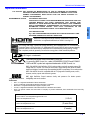
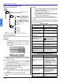
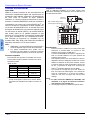
HDMI (High Definition Multimedia Interface)
Input Connection
About HDMI
HDMI is the first all-digital consumer electronics A/V
interface that supports several uncompressed standards,
enhanced and high definition video formats as well as
existing multi-channel audio format. One jack supports both
video and audio information. The HDMI/HDCP
1
input can
be connected to an EIA/CEA 861
2
compliant consumer
electronic device, such as a set top box or DVD player
equipped with an HDMI or DVI output connection. By
inputting a HDCP high definition picture source to the HDMI
terminal of this Projection Television, high definition
pictures can be displayed on the screen in their digital form.
The HDMI input terminal is not intended to be used with
personal computers. This Projection Television is
compatible with 1080i, 720p, 480p and 480i formats. Select
the output of the connecting device to match that of the
Projection Television.
Notes:
1. HDMI/HDCP = High Definition Multimedia Interface /
High-Bandwidth Digital Copy Protection.
2. EIA/CEA-861 = Compliance covers profiles for
transmission of uncompressed digital video including
high bandwidth digital content protection.
Compatible formats
Connection diagram
Follow the diagram below to connect the Projection Television to a
set top box or a DVD player.
Procedure
• Connect the HDMI output from the set top box or a DVD
player to the HDMI input on the back of the Projection
Television.
• Press TV/VIDEO button on the remote control to select
HDMI input. The interface on the Projection Television is
an HDMI Type A connector.
• If the external device has a DVI output only, use a DVI to
HDMI adaptor cable*
3
to connect to the HDMI jack on
the Projection Television. Also, connect the Audio Out
signal from the external device (set top box or DVD
player) to the Audio In*
4
jacks below the HDMI input.
• If you cannot display the picture because your Digital Set
Top Box does not have a Digital Out terminal setting, use
the Component Video Input (or the S-Video Input or
Video Input). In this case, the picture will be displayed as
an analog signal.
Notes:
*3. HDMI-DVI conversion cable (TY-SCH03DH) available
on Panasonic Website: www.panasonic.com (for
USA only).
*4. Please refer to page 22 for Audio setting detail.
This Projection Television is compatible with the following
formats. Please set the connecting device to the following
format.
Video signal
Audio signal
When digital audio is included in the HDMI connection,
the compatible sampling frequencies are 48 KHz /
44.1KHz / 32 KHz.
Format No. of pixels
Vertical scanning
frequency (Hz)
1080i 1920 x 1080i 59.94 / 60
720p 1280 x 720p 59.94 / 60
480p
720 x 480p
640 x 480p
59.94 / 60
59.94 / 60
480i 720 x 480i 59.94 / 60
Incoming
Cable
EXTERNAL DIGITAL
COMPONENT
AUDIO OUT
RL
HDMI
OUT
Note: Use anolog audio when no
digital audio is available.
CABLES NOT INCLUDED
TERMINALS ON BACK OF TELEVISION
Y
P
B
PR
L
R
Y
PB
PR
L
R
Y
PB
PR
L
R
VIDEO
L
R
AUDIO
L
R
AUDIO
VIDEO
S-VIDEO
IN 1 IN 2 OUT IN 1 IN 2 IN 3
COMPONENT VIDEO INPUT
R-AUDIO IN-L
HDMI
AV IN
RGB 1 IN
AUDIO IN
ANT
* The connector on the Projection Television is HDMI Type A connector.

SPECIAL FEATURES
13 z
ENGLISH
Special Features
ASPECT Button
Note: Aspect is not available while in RGB and HDMI mode.
The ASPECT button on the remote control lets you choose
one of four display modes, depending on the formats of the
received signal and your preferences.
BBE Button
Press this button to turn BBE VIVA 3D sound feature On or Off.
SAP Button
Press this button to let you cycle through different audio modes.
For example:
• If receiving STEREO, SAP and MONO or receiving
STEREO and MONO only, pressing SAP button will
toggle the audio as follows:
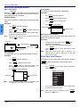
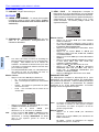
Split-Screen Operation
Note: Split-Screen is not available while in RGB and HDMI
mode.
This feature lets you watch two different signal sources
side by side with or without an external video source.
Note: Main picture and Split frame cannot display the same picture.
Procedure
• Press to display Split frame.
• Choose channels for the SPLIT frame by pressing
, to use the remote control numeric keypad
to change channel in Split frame. Press ,
then the right indicator ( ) will appear.
Note: Numeric keypad can only be used for split frame while
right indicator ( ) is displayed.
• Select channels for the Main picture by pressing
or use the remote control numeric keypad.
• Press to switch the SPLIT FRAME and MAIN
PICTURE source.
• Press to view picture source status.
• Press to cancel Split frame.
Split-Screen Operation With a Cable Box
To view premium (scrambled) cable channels through your
cable box in the Main Picture:
Note: Use this procedure if you want to watch premium cable
channels in the Main Picture while viewing a television
program or video in the Split frame.
Procedure
• Tune TV to channel 3 or 4.
• Press on the remote control to display Split
frame.
Note: Audio is from the Main Picture only.
• Verify that the cable box is ON.
• Choose channels for the Main Picture by tuning the
cable box.
• Choose channels for the SPLIT frame by pressing
.
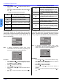
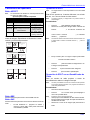
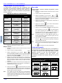
Customer Options depending on Component Input Signal
INPUT
SIGNAL
DISPLAY ON SCREEN
ASPECT BUTTON
OPTIONS
1080i
720p
16:9 only No options
480p (16:9) Default to 16:9
4:3, Full or Zoom (see
below)
480p (4:3)
Default to FULL mode.
Note: Will stretch picture
horizontally.
4:3, Full or Zoom (see
below)
480i Default to JUST mode
4:3, Full, Just or
Zoom (see below)
Input Signal
4
3
Image on
16:9 Screen Size
4:3
480i or 480p
ASPECT
The 4:3 mode will display a
4:3 picture at its standard 4:3
size with black side bars.
480i or 480p
Input Signal
Image on
16:9 Screen Size
ZOOM
16
9
ASPECT
Zoom will expand the 4:3
picture uniformly (width and
height) to full screen width
and then reposition the
picture vertically.
(Recommended for letterbox
pictures.)
480i or 480p
Input Signal
Image on
16:9 Screen Size
FULL
16
9
ASPECT
FULL will show picture at full
screen size. (Recommended
for anamorphic pictures.)
480i
JUST
16
9
Image on
16:9 Screen Size
Input Signal
ASPECT
JUST(justified) will stretch
the right and left edges of a
4:3 picture to fill the screen,
The center of the picture will
be normal (not stretched)The
size of the picture will depend
on the original signal.
(Recommended for regular
TV viewing.)
STEREO J SAP J MONO
SPLIT
SPLIT CH
DVD/VCR CH
SPLIT CTRL.
Change Main Picture channel
with numeric keypad.
Change Split Frame channel with
numeric keypad.
or
CH
CH
SWAP
R
E
C
A
L
L
SPLIT
SPLIT
SPLIT CH
DVD/VCR CH

14 z
SPECIAL FEATURES
ENGLISH
Split-Screen Operational Buttons
SPLIT CTRL Button
Pressing will enable you to use numeric keys
for changing split channel and to use TV/VIDEO button to
select desired input for Split frame.
TV/VIDEO Button
Press when Split frame is displayed to select desired input
mode.
Procedure
• Press to display Split frame.
• Press then to display video input
menu.
• Press corresponding number key on the remote control
to select the input of your choice.
Note: Split frame input mode can only be changed while right
indicator ( )is displayed.
Search Button
This feature lets you scan through all available channels.
Procedure
• Press to display split frame.
• Press to display search frames.
• Press again to stop search feature. Split
frame channel will be the last active search frame.
• Press to cancel split frame.
Note: When main picture is Photo Viewer™, Component, RGB
or HDMI signal, search feature is not available.
Freeze Button
This feature is used to stop action in Split frame.
Procedure
• Press to display split frame.
• Press to stop split frame action.
• Press again to continue action.
• Press to cancel frame.
Main Picture Freeze Feature
This feature is used to stop action of the Main Picture and
display it on a Split freeze frame.
Procedure
• To stop action for Main picture, press while
Split frame is not displayed.
• Main Picture freeze will be displayed in Split frame.
• Press again to cancel Main Picture freeze
frame.
Note: While Main Picture freeze frame is displayed, only
FREEZE button is active for Split frame. All other Split
buttons have no effect.
Direct Video Input Selection
This feature lets you select video inputs directly using the
and the numeric keys on the remote control.
Procedure
• Press on the remote control to display the
Input selection menu.
• Press corresponding number key on the remote control
to select the input of your choice.
Note: Video input can also be selected by pressing ,
then the CH STbuttons.
SPLIT CTRL.
SPLIT
SPLIT CTRL.
TV/VIDEO
Main Picture
TV
Split Frame
COMPONENT1/2/3
VIDEO 1/2/3
SPLIT
SEARCH
SEARCH
SPLIT
2
3
4
Search Frames
Main Picture
SPLIT
FREEZE
FREEZE
SPLIT
Main Picture
Split freeze frame
FREEZE
FREEZE
TV/VIDEO
TV/VIDEO
1 TV
2 COMPONENT1
3 COMPONENT2
4 COMPONENT3
5 HDMI
6 VIDEO1
7 VIDEO2
8 VIDEO3
9 RGB1
0 RGB2
TV/VIDEO

REMOTE CONTROL OPERATION
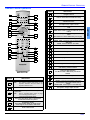
15 z
ENGLISH
Remote Control Operation
10
1
2
4
3
5
7
6
8
9
11
12
13
14
15
16
17
18
19
20
21
22
23
24
25
26
28
27
EUR7627Z20
BUTTON
NUMBER
DESCRIPTION
Press to turn ON and OFF.
Note: The ON/OFF indicator LED (green) on the
Projection Television will be lit when the
Projection Television is on.
Press to select TV, VCR or other device to operate.
Press to select TV or input modes for main picture
or split frame.
Note: Refer to TV/VIDEO Button section on page
14 for selecting split frame input.
Press to access Photo Viewer.
Also press while Photo Viewer is displayed to
access Photo Viewer set up menu.
Press to select picture shape to match
programming format.
Also used for Photo Viewer to change aspect
of the image on-screen while in slide mode.
Press to mute sound.
1
2
3
4
5
6
BUTTON
NUMBER
DESCRIPTION
Press to adjust Projection Television sound and
navigate in menus.
Press to choose menu and sub-menu entry.
Press to display Main Menu or return one step
backward in menus.
Press numeric keypad to select any channel or press to
enter alphanumeric input in menus.
Press to switch to previously viewed channel or input
mode.
Press to swap Main picture with Split frame.
REW - While remote is in VCR or DVD mode, press to
rewind.
Press to display Split frame, press again to delete Split
frame.
While remote is in VCR or DVD mode, press to play.
While remote is in VCR or DVD mode, press to pause.
FREEZE - While in TV mode, press to stop action in the
Split frame.
TV/VCR - Press to switch to TV or VCR.
Press to access audio modes (Stereo, SAP or Mono).
Press to illuminate remote buttons.
These buttons are not operational for this model.
Press to turn BBE VIVA 3D OFF or ON.
Press to display or delete Channel banner.
Press to exit menus.
Press to change channels and navigate in menus.
Press after entering major channel numbers to
enter minor (-) channel numbers.
Press to use numeric keypad and TV/VIDEO
buttons for Split operation.
FF - While in VCR or DVD mode, press to fast
forward.
While remote is in VCR mode, press to record.
While remote is in VCR or DVD mode, press to stop.
SEARCH - Press to scan available channels in
search frames. Press again to delete search
frames.
OPEN/CLOSE - Press to open or close DVD tray.
Press to change channels for Split frame or VCR.
Also press to change chapter for DVD.
7
8
9
10
11
12
13
14
15
16
17
18
19
20
21
22
23
24
25
26
27
28

16 z
REMOTE CONTROL OPERATION
ENGLISH
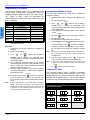
Programming The Remote
The Universal Remote Control can be programmed to
operate many manufacturers’ components, using the
component function buttons for VCR, DVD, AUX, RCVR,
DTV, CABLE or DBS. Follow the procedures for
programming your Remote Control with or without a code
for the component.
Note: Determine the manufacturer of the component and look
in the table for the code.
Procedure
1. Confirm that the external component is plugged and
operating.
2. Turn the component off.
3. Press and together, for at least 5
seconds. After 5 seconds, the illuminated mode
(component) buttons will begin to flash. Release the OK
and POWER buttons.
4. Press appropriate component button on the Remote
Control VCR, DVD (CD), DTV, RCVR, DBS/CBL or AUX
(PVR or VCR2). The component button will illuminate
steadily and all others will go out.
5. Enter the 3-digit component code using the Remote
Control numeric keypad (0 ~ 9 buttons). The component
button will blink twice.
6. Press the Remote Control to test the component.
If the procedure was successful, the component will
turnon and the component key will blink twice and then
go out.
Note: If the component does not operate with the Remote
Control, repeat steps 3 through 6 using another code.
(Some brands have multiple codes.) If an incorrect code
is entered, or if the procedure takes longer than 30
seconds, the programming will fail.
Programming Without A Code
This procedure searches all codes and is called the
“sequence method.”
1. Confirm that the external component is plugged in and
on.
2. Turn the component off.
3. Press and together, for at least 5
seconds. After 5 seconds, the illuminated mode
(component) buttons will begin to flash. Release the OK
and POWER buttons.
4. Press appropriate component button on the Remote
Control.
5. Press the button to place the remote control into
the step and set mode.
6. Point the remote control towards the component.
7. Press VOL X (the mode key will blink three times), then
press the Remote Control to test the component.
Continue this process until the proper code is found. If
the procedure was successful, the component will turn
on.
Note: Each time you press the VOL X button, make sure that
the component key blinks twice before pressing the
POWER button.
8. Once the device responds, press to store the
code. The mode (component) button will blink twice.
Note: It may take many attempts before the correct code
is found. If you miss a code, press W VOL, then press
the button to test the component.
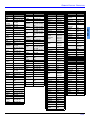
Component Codes
The Universal Remote Control is capable of operating
many component brands after entering a code. Some
components may not operate because the codes are not
available due to limited memory. The Universal Remote
Control does not control all features found in each model.
Device Operates Default
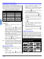
TV
TV (Panasonic Only) Panasonic Code
VCR
VCR (Preset) Panasonic Code
DVD
DVD and CD (Preset) DVD Panasonic Code
DBS/
CABLE
DBS & CBL (Preset) Panasonic DBS Code
RCVR
Audio Receiver (Preset) Panasonic RCVR Code
DTV
DTV (Panasonic Only) Panasonic DTV Code
AUX
Personal Video Recorders,
Cassette and VCR2
Panasonic Personal
Video Recorder Code
OK
POWE
R
POWE
R
Write the code numbers from tables in this space.
This will serve as a reference if you need to program
your Remote Control.
VCR DVD DVD (CD)
DBS RECEIVER CABLE
AUX (PVR) AUX (VCR2)
OK
POWE
R
POWER
POWE
R
OK
POWER

REMOTE CONTROL OPERATION
17 z
ENGLISH
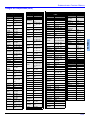
Codes For VCR
Brand Code
Admiral
335
Aiwa
332
Akai
314, 315, 316, 329
Audio
Dynamic
311, 339
Bell & Howell
305, 313
Broksonic
320, 326
Canon
323, 325
CCE
343
Citizen 306
Craig
305, 306, 329
Curtis
Mathes
324, 345
Daewoo
301, 324, 343
DBX
310, 311, 339
Dimensia
345
Emerson
303, 319, 320, 325,
326, 343
Fisher
305, 307, 308, 309,
313
Funai
320, 326, 334
GE
324, 333, 345
Goldstar
306
Gradiente
334
Hitachi
300, 323, 345
Instant
Replay
323, 324
Jensen
339
JVC
310, 311, 334, 339
Kenwood
306, 310, 311, 339
LXI
300, 305, 306, 307,
308, 309
Magnavox
323, 324, 331
Marantz
310, 311, 339
Marta
306
Memorex
309, 324
MGA
338, 340, 341, 347,
348
Minolta
300, 345
Mitsubishi
338, 340, 341, 347,
348
Multitech
304, 347
NEC
310, 311, 334, 339
Olympic
323, 324
Optimus
306, 321, 328, 335
Orion
320, 326
Panasonic
321, 322, 323, 324
Penney
300, 305, 310, 311,
324, 339, 345
Pentax
300, 311, 345
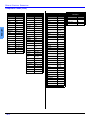
Codes For VCR (Cont.)
Brand Code
Philco
320, 323, 324, 326,
331, 343
Philips
323, 324, 331
Pioneer
323
Proscan
300, 301, 302, 323,
324, 331, 333, 345,
346
Quasar
321, 322, 323, 324
Radio Shack
305, 309, 324, 333,
336, 340
RCA
300, 301, 302, 323,
324, 331, 333, 345,
346
Realistic
305, 309, 324, 336,
340
Samsung
302, 304, 333
Sansui
320, 326, 339, 352
Sanyo
305, 309, 313
Scott
301, 302, 304, 309,
320, 326, 338, 340,
347, 348
Sears
300, 305, 306, 307,
308
Sharp
335, 336
Shintom
317
Signature
2000
335
Singer
337
Sony
328, 329, 330
Sylvania
323, 324, 331
Tashiro
306
Tatung
310, 311, 339
Teac
310, 311, 339
Technics
321, 322, 323, 324
Teknika
324
Toshiba
301, 346
Vector
Research
311
Wards
306, 309, 335, 336,
344
Yamaha
305, 310, 311, 339
Zenith
306,344
Codes For Cable Box
Brand Code
ABC 224
Archer 225, 232
Cableview 205, 232
Citizen 205, 222
Curtis 212, 213
Diamond 224, 225, 232
Eagle 229
Eastern 234
GCbrand 205, 232
Gemini 222
General
Instrument/
Jerrold
211, 219,
220, 221,
222, 223,
224, 225,
226, 227
Hamlin
212, 218,
240, 241,
242, 245
Hitachi 203, 224
Macom 203, 204, 205
Magnavox
233
Memorex 230
Movietime 205, 232
Oak 202, 237, 239
Panasonic 209, 210, 214
Philips
206, 207,
228, 229, 230
Pioneer 201, 216
Pulsar 205, 232
Puser 232
RCA 215
Realistic 232
Regal
212, 218,
240, 241,
242, 245,
Regency 234
Rembrandt 205, 232, 237
Samsung 205
Scientific Atlanta 211, 212, 213
Slmark 201, 205
Sprucer 205, 210
Stargate 205, 232
Teleview 201, 205
Texscan 244
Tocom 235
Toshiba 204
Unika 225, 232
Universal 122, 132
Videoway 106
Viewstar 129, 130
Zenith 100, 117
Zenith/.Drake
Satellite
100
Codes For DBS
Brand Code
Dish Network
(Echostar)
105, 115, 116
Echostar 105
Express VU 105, 115
G. E. 106
G.I. (General
Instrument)
108
Gradiente 114
Hitachi 103, 111,
112
HNS (Hughes) 103
Magnavox 101, 102
Panasonic 104
Philips 101, 102
Primestar 108
Proscan
106, 109, 110,
113
RCA 106, 109,
110, 113
Sony 107
Star Choice
103, 108
Toshiba 100
Uniden 101, 102
Zenith 127
Codes For DVD
Brand Code
Denon 100
Ferguson 101
JVC 109
Mitsubishi 105
Nordmende 101
Panasonic 100
Philips 103
Pioneer 102
RCA 101
Saba 101
Samsung 110
Sharp 108
Sony 104
Technics 100
Thomson 101
Toshiba 103
Yamaha 100
Zenith 107

18 z
REMOTE CONTROL OPERATION
ENGLISH
Component Codes (Cont.)
Codes For Cassette Decks
Brand Code
Aiwa
223, 224, 225
Denon 231
Fisher 203
Jensen 214
JVC 229, 230
Kenwood 200, 207
Marantz 202
Nakamichi 205
Onkyo 208, 209, 213
Panasonic 216, 218
Philips 222
Pioneer 204
RCA 226, 227, 228
Sansui 205, 210
Sharp 231
Sony 219, 220
Teac 210, 211, 215
Technics 216, 218
Yamaha 201, 202
Codes For Receivers
Brand Code
Admiral 120
Aiwa 125, 126
Denon 134, 135, 136
Fisher 104
Garrard 113
Harman
Kardon
115, 123
Jensen 129
JVC 132, 133
Kenwood 100, 108
Magnavox 127
Marantz 124
Mclntosh 116
Nakamichi 106
Onkyo 109, 114
Optimus
103, 127, 130,
131
Panasonic 118, 119, 121
Philips 123
Pioneer 105, 107
Quasar 118, 119, 121
RCA
103, 105, 127,
130, 131
Sansui 103, 111, 139
Sharp 134, 137
Sony 122
Soundesign 138
Teac 111, 112, 113
Technics 118, 119, 121
Victor 132, 133
Yamaha 101, 102
Codes For CD Player
Brand Code
Admiral 226
Aiwa 233, 235
Carver 229
Denon 242
Emerson 239
Fisher 205
Harman/Kardon
219, 220,
221, 223
Hitachi 207
Jensen 234
JVC 240, 241, 245
Kardon 223
Kenwood
200, 201, 211,
245
LXI/Sears 236
Magnavox 229, 232
Marantz 229
McIntosh 221
Nakamichi 210
Onkyo 214, 215
Optimus
208, 218,
220, 222
Panasonic 224, 225, 227
Philips 229, 230
Pioneer 208
Quasar 224, 225, 227
RCA
231, 237,
238, 247
Sansui 210, 246
Sanyo 205
Scott 210, 246
Sharp 242, 243
Sherwood 220
Sony 228
Soundesign 244
Teac 212, 216, 218
Technics 224, 225, 227
Victor 240, 241, 245
Yamaha 202, 203, 204
Codes For Personal Video
Recorders
Brand Code
Panasonic Replay
TV
100
Philips Tivo 102
Sony Tivo 101
La page est en cours de chargement...
La page est en cours de chargement...
La page est en cours de chargement...
La page est en cours de chargement...
La page est en cours de chargement...
La page est en cours de chargement...
La page est en cours de chargement...
La page est en cours de chargement...
La page est en cours de chargement...
La page est en cours de chargement...
La page est en cours de chargement...
La page est en cours de chargement...
La page est en cours de chargement...
La page est en cours de chargement...
La page est en cours de chargement...
La page est en cours de chargement...
La page est en cours de chargement...
La page est en cours de chargement...
La page est en cours de chargement...
La page est en cours de chargement...
La page est en cours de chargement...
La page est en cours de chargement...
La page est en cours de chargement...
La page est en cours de chargement...
La page est en cours de chargement...
La page est en cours de chargement...
La page est en cours de chargement...
La page est en cours de chargement...
La page est en cours de chargement...
La page est en cours de chargement...
La page est en cours de chargement...
La page est en cours de chargement...
La page est en cours de chargement...
La page est en cours de chargement...
La page est en cours de chargement...
La page est en cours de chargement...
La page est en cours de chargement...
La page est en cours de chargement...
La page est en cours de chargement...
La page est en cours de chargement...
La page est en cours de chargement...
La page est en cours de chargement...
La page est en cours de chargement...
La page est en cours de chargement...
La page est en cours de chargement...
La page est en cours de chargement...
La page est en cours de chargement...
La page est en cours de chargement...
La page est en cours de chargement...
La page est en cours de chargement...
La page est en cours de chargement...
La page est en cours de chargement...
La page est en cours de chargement...
La page est en cours de chargement...
La page est en cours de chargement...
La page est en cours de chargement...
La page est en cours de chargement...
La page est en cours de chargement...
La page est en cours de chargement...
La page est en cours de chargement...
La page est en cours de chargement...
La page est en cours de chargement...
La page est en cours de chargement...
La page est en cours de chargement...
La page est en cours de chargement...
La page est en cours de chargement...
La page est en cours de chargement...
La page est en cours de chargement...
La page est en cours de chargement...
La page est en cours de chargement...
La page est en cours de chargement...
La page est en cours de chargement...
La page est en cours de chargement...
La page est en cours de chargement...
La page est en cours de chargement...
La page est en cours de chargement...
La page est en cours de chargement...
La page est en cours de chargement...
La page est en cours de chargement...
La page est en cours de chargement...
La page est en cours de chargement...
La page est en cours de chargement...
La page est en cours de chargement...
La page est en cours de chargement...
La page est en cours de chargement...
La page est en cours de chargement...
La page est en cours de chargement...
La page est en cours de chargement...
La page est en cours de chargement...
La page est en cours de chargement...
La page est en cours de chargement...
La page est en cours de chargement...
-
 1
1
-
 2
2
-
 3
3
-
 4
4
-
 5
5
-
 6
6
-
 7
7
-
 8
8
-
 9
9
-
 10
10
-
 11
11
-
 12
12
-
 13
13
-
 14
14
-
 15
15
-
 16
16
-
 17
17
-
 18
18
-
 19
19
-
 20
20
-
 21
21
-
 22
22
-
 23
23
-
 24
24
-
 25
25
-
 26
26
-
 27
27
-
 28
28
-
 29
29
-
 30
30
-
 31
31
-
 32
32
-
 33
33
-
 34
34
-
 35
35
-
 36
36
-
 37
37
-
 38
38
-
 39
39
-
 40
40
-
 41
41
-
 42
42
-
 43
43
-
 44
44
-
 45
45
-
 46
46
-
 47
47
-
 48
48
-
 49
49
-
 50
50
-
 51
51
-
 52
52
-
 53
53
-
 54
54
-
 55
55
-
 56
56
-
 57
57
-
 58
58
-
 59
59
-
 60
60
-
 61
61
-
 62
62
-
 63
63
-
 64
64
-
 65
65
-
 66
66
-
 67
67
-
 68
68
-
 69
69
-
 70
70
-
 71
71
-
 72
72
-
 73
73
-
 74
74
-
 75
75
-
 76
76
-
 77
77
-
 78
78
-
 79
79
-
 80
80
-
 81
81
-
 82
82
-
 83
83
-
 84
84
-
 85
85
-
 86
86
-
 87
87
-
 88
88
-
 89
89
-
 90
90
-
 91
91
-
 92
92
-
 93
93
-
 94
94
-
 95
95
-
 96
96
-
 97
97
-
 98
98
-
 99
99
-
 100
100
-
 101
101
-
 102
102
-
 103
103
-
 104
104
-
 105
105
-
 106
106
-
 107
107
-
 108
108
-
 109
109
-
 110
110
-
 111
111
-
 112
112


Panasonic Projection Television PT 50DL54 Manuel utilisateur
- Catégorie
- Équipement musical supplémentaire
- Taper
- Manuel utilisateur
- Ce manuel convient également à
dans d''autres langues
Documents connexes
-
Panasonic PT43LC14K Mode d'emploi
-
-
-
-
-
-
-
-
-
Autres documents
-
Philips 27G7 Mode d'emploi
-
Toshiba Projection Television 44HM85 Manuel utilisateur
-
Memorex MDF0712-C Manuel utilisateur
-
-
Yamaha DPX-1000 Manuel utilisateur
-
Yamaha Projector DPX-1200 Manuel utilisateur
-
-
Sanyo RMT-U340 Le manuel du propriétaire
-
HP PL4272N Guide d'installation
-
JVC JX-66 Manuel utilisateur