Simplicity 040434-00 Manuel utilisateur
- Catégorie
- Groupes électrogènes
- Taper
- Manuel utilisateur

Installation &
Operator’s Manual
Manuel d'installation
et d'utilisation
Manual de Instalación
y del Operario
Questions? Help is just a moment away!
Vous avez des questions? Vous n'avez pas
besoin d'aller loin pour trouver de l'aide!
¿Preguntas? ¡La ayuda está muy cerca!
Call: Home Generator Helpline
Appelez: Ligne Directe de GÉNÉRATRICE
LRÉSIDENTIELLE
Llame: Línea Directa de Generador de Hogar
1-800-743-4115 M-F 8-5 CT
BRIGGSandSTRATTON.com
Models 071014 & 071017 Part No. 198417GS Rev. - (08/15/06)
30A NEMA 1 / NEMA 3R
Switching Neutral
Manual Transfer Switch

TABLE OF CONTENTS
2
TABLE OF CONTENTS
TABLE OF CONTENTS . . . . . . . . . . . . . . . . . . . . . . . 2
IMPORTANT SAFETY INSTRUCTIONS . . . . . . . . . . 3
INTRODUCTION . . . . . . . . . . . . . . . . . . . . . . . . . . . . 4
For the Home Owner. . . . . . . . . . . . . . . . . . . . . . 4
For the Installing Dealer/Contractor. . . . . . . . . . . 4
Owner Orientation . . . . . . . . . . . . . . . . . . . . . . . . 5
Installer Responsibilities . . . . . . . . . . . . . . . . . . . 5
Equipment Description . . . . . . . . . . . . . . . . . . . . 5
Generator Compatibility . . . . . . . . . . . . . . . . . . . . 5
INSTALLATION. . . . . . . . . . . . . . . . . . . . . . . . . . . . . . 6
Unpacking . . . . . . . . . . . . . . . . . . . . . . . . . . . . . . 6
Delivery Inspection . . . . . . . . . . . . . . . . . . . . 6
Mounting Guidelines . . . . . . . . . . . . . . . . . . . . . . 7
ESSENTIAL CIRCUIT ISOLATION . . . . . . . . . . . . . . 8
Power Wiring Interconnections . . . . . . . . . . . . 9-10
Inlet Box. . . . . . . . . . . . . . . . . . . . . . . . . . . . . 11-12
Connecting Cord Set . . . . . . . . . . . . . . . . . . 12
SYSTEM OPERATION . . . . . . . . . . . . . . . . . . . . . . . 13
Load Management. . . . . . . . . . . . . . . . . . . . . . . 13
SPECIFICATIONS . . . . . . . . . . . . . . . . . . . . . . . . . . 14
Model 071014 . . . . . . . . . . . . . . . . . . . . . . . 14
Model 071017 . . . . . . . . . . . . . . . . . . . . . . . 14
When Calling The Factory . . . . . . . . . . . . . . . . . 14
TROUBLESHOOTING . . . . . . . . . . . . . . . . . . . . . . . 15
SERVICE PARTS . . . . . . . . . . . . . . . . . . . . . . . . . . . 16
WARRANTY . . . . . . . . . . . . . . . . . . . . . . . . . . . . . . . 17
Copyright © 2006 Briggs & Stratton Power Products
Group, LLC. All rights reserved. No part of this
material may be reproduced or transmitted in any form
by any means without the express written permission
of Briggs & Stratton Power Products Group, LLC.
is a registered trademark of Briggs & Stratton
Corporation, Milwaukee, WI, U.S.A.

IMPORTANT SAFETY INSTRUCTIONS
3
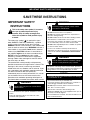
IMPORTANT SAFETY
INSTRUCTIONS
This is the safety alert symbol. It is used to
alert you to potential personal injury
hazards. Obey all safety messages that
follow this symbol to avoid possible injury
or death.
The safety alert symbol ( ) is used with a signal
word (DANGER, CAUTION, WARNING), a pictorial
and/or a safety message to alert you to hazards.
DANGER indicates a hazard which, if not avoided, will
result in death or serious injury. WARNING indicates a
hazard which, if not avoided, could result in death or
serious injury. CAUTION indicates a hazard which, if
not avoided, might result in minor or moderate injury.
NOTICE, when used without the alert symbol,
indicates a situation that could result in equipment
damage. Follow safety messages to avoid or reduce
the risk of injury or death.
The manufacturer cannot possibly anticipate every
possible circumstance that might involve a hazard. The
warnings in this manual, and the tags and decals
affixed to the unit are, therefore, not all-inclusive. If you
use a procedure, work method or operating technique
that the manufacturer does not specifically
recommend, you must satisfy yourself that it is safe for
you and others. You must also make sure that the
procedure, work method or operating technique that
you choose does not render the transfer switch unsafe.
SAVE THESE INSTRUCTIONS
• DO NOT touch bare wires or receptacles.
• DO NOT use transfer switch with worn, frayed, bare or
otherwise damaged wiring.
• DO NOT handle electrical cords while standing in water,
while barefoot, or while hands or feet are wet.
• If you must work around a unit while it is operating, stand
on an insulated dry surface to reduce shock hazard.
• DO NOT allow unqualified persons or children to operate
or service transfer switch.
• In case of an accident caused by electrical shock,
immediately shut down the source of electrical power and
contact local authorities. Avoid direct contact with the
victim.
Failure to properly ground transfer switch
can result in electrocution.
WARNING
• Use transfer switch only for intended uses.
• If you have questions about intended use, ask dealer or
contact Briggs and Stratton Power Products.
• DO NOT expose transfer switch to excessive moisture,
dust, dirt, or corrosive vapors.
• Remain alert at all times while working on this
equipment. NEVER work on the equipment when you are
physically or mentally fatigued.
• If connected devices overheat, turn them off and turn off
their circuit breaker/fuse.
Improper treatment of transfer switch can damage
it and shorten its life.
NOTICE
• Despite the safe design of the transfer switch, operating
this equipment imprudently, neglecting its maintenance or
being careless can cause possible injury or death.
Transfer Switch contains hazardous voltage
that can cause personal injury or death.
WARNING
• Licensed electrician must perform installation of transfer
switch.
• Follow all applicable federal, state and local codes,
standards and regulations.
Contact with live parts can cause electric
shock or burn.
WARNING

INTRODUCTION
4
INTRODUCTION
Thank you for your purchase of this Briggs & Stratton
Switching Neutral Manual Transfer Switch. This transfer
switch is designed for use with generators equipped
with or without Ground Fault Circuit Interrupters (GFCI).
The switch disconnects the appropriate neutral circuit to
allow the GFCI to function properly.
This transfer switch is for use with optional home
standby systems which provide an alternate source of
electric power and to serve loads such as a gas
furnace, refrigeration and communication systems that,
when stopped during any power outage, could cause
discomfort, or the like. This product DOES NOT qualify
for emergency standby as defined by NFPA 70 (NEC).
Briggs and Stratton Power Products (BSPP) has made
every effort to provide for a safe, streamlined and cost-
effective installation. Each installation is unique, it is
impossible to know of and advise of all conceivable
procedures and methods by which installation might
be achieved. We do not know all possible hazards
and/or the results of each method or procedure. For
these reasons,
Only licensed electricians
should install transfer switches.
Installations must strictly comply with all
applicable federal, state and local codes,
standards and regulations.
Your BSPP Transfer Switch is supplied with this
combined “Installation and Operator’s Manual”. This is
an important document and should be retained by the
owner after the installation has been completed.
Every effort has been expended to make sure that the
information in this manual is both accurate and
current. However, the manufacturer reserves the right
to change, alter or otherwise improve the system at
any time without prior notice.
For the Home Owner
To help you make informed choices and communicate
effectively with your installation contractor(s),
Read and understand the
Owner Orientation Section of this manual
BEFORE
contracting or starting
your transfer switch installation.
To arrange for proper installation, contact the store at
which you purchased your BSPP Transfer Switch, your
dealer, or your utility power provider.
The Transfer Switch Warranty is V
OID
unless the system is installed by a
licensed electrical professional.
For the Installing Dealer/Contractor
• Check federal, state and local codes for questions
on installation.
• If you need more information about the transfer
switch, call 1-800-743-4115, between 8:00 AM and
5:00 PM CT.

INTRODUCTION
5
Owner Orientation
The provided illustrations deplict typical circumstances
and are meant to familiarize you with the installation
options available with your transfer switch.
Local codes, appearance, and distances are factors
that must be considered when negotiating with an
installation professional. As the distance from the
existing electrical service increases, compensation in
wiring materials must be allowed for. This is necessary
to comply with local codes and overcome electrical
voltage drops.
The factors mentioned above will have a direct effect
on the overall price of your transfer switch
installation.
NOTE: Your installer must check local codes AND
obtain permits before installing the system.
Read and follow the instructions given in this manual.
Installer Responsibilities
• Read and observe the safety rules.
• Read and follow the instructions given in this
manual.
• Check federal, state and local codes, standards and
regulations.
• Ensure generator is not overloaded with selected
loads.
Equipment Description
This transfer switch is intended to operate electrical
loads found in normal residential installations. The load
is connected either to utility power (normal) or home
standby power (generator).
The manual transfer switch is equipped with two main
circuit breakers (“GENERATOR SUPPLY” and
“UTILITY SUPPLY”) and a mechanical interlock. The
“GENERATOR SUPPLY” circuit breaker connects
power from the generator to the load devices wired to
the manual transfer switch. The “UTILITY SUPPLY”
circuit breaker connects utility power from the
distribution panel to the loads wired to the manual
transfer switch. Each of these circuit breakers have an
isolated neutral that MUST be connected inside the
transfer switch.
The mechanical interlock allows the circuit breakers for
either the generator power “GENERATOR SUPPLY” or
the utility power “UTILITY SUPPLY” to be turned on to
provide power to the selected house loads. This
switching neutral manual transfer switch will not allow
utility line power and generator power to be connected
to a load device at the same time.
If utility line power is restored while generator power is
being used, there will be no effect on the generator or
transfer switch components. When utility power is
restored, follow the instructions in the section “System
Operation”.
Generator Compatibility
Only use a generator that is factory-equipped with a
NEMA L14-20R or NEMA L14-30R receptacle, shown
in Figures 9 and 10.
• NEVER connect transfer switch to any receptacle other
than those recommended as damage to connected
appliances may occur.
NOTICE

INSTALLATION
6
INSTALLATION
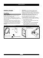
Unpacking
Delivery Inspection
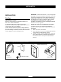
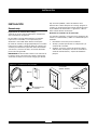
Remove the Transfer Switch components shown in
Figure 1 from the shipping carton.
The transfer switch is supplied ready for installation.
Inspect the switch and its attached components for any
shipping damage.
The inlet box is supplied ready to be wired. Inspect it,
the connection cord set, and the connecting plugs for
any damage. The installer will select and connect the
appropriate connection cord plug to match generator
receptacle.
IMPORTANT: If loss or damage is noted at time of
delivery, have the person(s) making delivery note all
damage on the freight bill and affix his signature under the
consignor's memo of loss or damage. If loss or damage is
noted after delivery, contact the carrier for claim
procedures. Freight damaged parts are not warranted.
Items Not Shipped with Transfer Switch:
The following items, required for system installation,
are not included and must be provided by the installer:
1. Tools required for installation
2. Anchors and screws to mount the transfer switch
components and conduit.
3. Conduit, fittings, wire nuts, and insulated copper
wire for connecting the transfer switch to the
outside inlet box and main distribution panel.
Inlet Box
Connecting Cord Set
Transfer Switch
(Model 071014 shown)
Manual
Connecting Plugs
Figure 1 — Transfer Switch Components

Mounting Guidelines
The Model 071014 Switching Neutral Manual Transfer
Switch is enclosed in a NEMA Type 1 enclosure
suitable for indoor use ONLY.
The Model 071017 Manual Transfer Switch is enclosed
in a NEMA Type 3R enclosure suitable for
indoor/outdoor use.
Guidelines for mounting the Switching Neutral Manual
Transfer Switch include:
• Model 071017 Switching Neutral Manual Transfer
Switch must be installed with minimum NEMA 3R
hardware for conduit connections.
• Install switch on a firm, sturdy supporting structure.
• Ensure enclosure is level and plumb. This can be
done by placing washers between switch enclosure
and mounting surface.
• NEVER install switch where any corrosive substance
might drip onto enclosure.
• Protect switch at all times against excessive moisture,
dust, dirt, lint, construction grit and corrosive vapors.
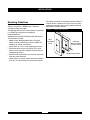
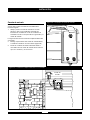
The typical installation of the Switching Neutral Manual
Transfer Switch is depicted in Figure 2. Discuss layout
suggestions/changes with the owner before beginning
the system installation process.
INSTALLATION
7
Switching
Neutral Manual
Transfer Switch
Main
Distribution
Panel
Figure 2 — Typical Switch Mounting
Model 071014 shown

ESSENTIAL CIRCUIT
ISOLATION
Essential electrical loads are loads that will be powered
by the Home Generator System. Essential loads are
grouped together and wired into the transfer switch.
TO THE INSTALLER: Consult with Home
Generator System owner(s) to discuss their
selection of essential circuits, described in
generator operator’s manual.
DO NOT overload generator as described in generator
operator’s manual.
The Switching Neutral Manual Transfer Switch is
connected to the branch circuit side in the main
distribution panel.
All wiring must conform to federal, state and local
codes.
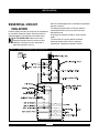
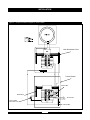
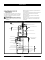
The illustration in Figure 3 depicts the Home
Generator System while utility is supplying
120/240 Volt, single-phase electrical service.
Figure 3 — Typical System Diagram with Essential Circuits
INSTALLATION
8

INSTALLATION
9
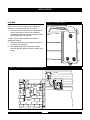
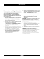
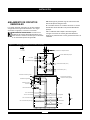
Power Wiring Interconnections
All wiring must be the proper size, properly supported
and protected by conduit. Ensure all power is
disconnected during installation.
Complete connections between the inlet box, main
distribution panel and the transfer switch per Figure 4
on the next page.
1. Connect utility feeder from two pole 50 Amp
branch circuit breaker in main distribution panel, to
transfer switch 50 Amp breaker marked “Utility
Supply”.
2. Connect main distribution panel neutral to transfer
switch 50 Amp breaker neutral marked “Utility
Supply”. DO NOT connect to neutral or ground bus
in transfer switch.
3. Connect main distribution panel equipment ground
to equipment ground bus in transfer switch.
4. Connect generator feeder from receptacle in inlet
box to transfer switch 30 Amp breaker marked
“Generator Supply”.
5. Connect generator neutral from receptacle in inlet
box to transfer switch 30 Amp breaker neutral
marked “Generator Supply” DO NOT connect to
neutral or ground bus in transfer switch.
6. Connect generator equipment ground from
receptacle in inlet box to transfer switch ground
bus.
IMPORTANT: Connecting the transfer switch neutral
bus to ground will trip the generator GFCI. DO NOT
connect the transfer switch neutral bus to ground.
7. Connect all branch circuit breakers to appropriate
essential circuits, including line and neutral circuit
conductors.
8. Tighten all wire connections and fasteners to
proper torque.
NOTE: Utility and Generator branch circuit breakers in
transfer switch are specially designed to disconnect
appropriate neutral circuits during operation. This
feature allows the use of Ground Fault Circuit
Interrupter devices on generators when installed
correctly.

INSTALLATION
10
Figure 4 — A Typical Installation Diagram for Transfer Switch
Neutral Bus
Neutral Bus
To Inlet Box
Ground Bus
Typical 120V
Essential Load
Main Distribution Panel
Transfer Switch

INSTALLATION
11
Inlet Box
Installation must strictly comply with all applicable
federal, state and local codes when installing the
generator inlet box provided with this system.
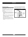
1. Locate and mount inlet box on an outside wall as
close as possible to transfer switch. However,
consider household air intake ducting when when
locating generator and inlet box.
A typical transfer switch complete installation is
depicted in Figure 5.
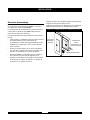
2. Remove inlet box inner panel. Mount inlet box on
an outside wall (Figure 6).
3. Run appropriately sized conduit from transfer
switch to inlet box. Anchor all boxes, conduit, and
fittings.
Figure 6 — Inlet Box Installation
Figure 5 — A Typical Completed Transfer Switch Installation
Inlet Box
Transfer
Switch
Main
Distribution
Panel

INSTALLATION
12
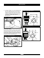
4. As shown in Figure 7, cut, strip, and connect each
wire to the appropriate terminal on the locking
receptacle on the inlet box inner panel. Use the
schematic affixed to the inside of the inlet box to
make proper wire connections. When all
connections have been made, reinstall the inlet
box inner panel.
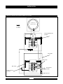
Connecting Cord Set
From the two 120/240 Volt connection plugs supplied
with the transfer switch, select the one that mates to
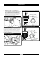
the generator. Referring to the image in Figure 8 and
the schematic in Figure 9 or Figure 10 that applies to
the connector being used, properly attach the plug to
the pigtail end of the connecting cord set.
Figure 9 — 20A Cord Set Connector
4-Wire Cord Set
240V
120V
120V
W (Neutral)
X (Hot)
Y (Hot)
NEMA L14-20
Ground (Green)
Figure 10 — 30A Cord Set Connector
4-Wire Cord Set
240V
120V
120V
W (Neutral)
X (Hot)
Y (Hot)
NEMA L14-30
Ground (Green)
Figure 8 — Receptacle Connection
Figure 7 — Inlet Box Connections

OPERATION
13
SYSTEM OPERATION
Load Management
The number of circuits that can be operated
simultaneously during a utility failure will depend on the
wattage capacity of your generator. Most optional
standby system generators do not have the
capacity to handle loads on all transfer switch
circuits at the same time.
Review the load management plan developed with the
installer. It may be necessary to selectively turn on and
off certain loads while using generator power so that
necessary appliances can be operated.
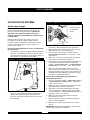
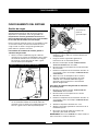
To transfer from utility power to generator power:
1. Align female socket of connecting cord set with
inlet box receptacle’s mating male prongs, as
shown in Figure 11. Push cord set connector in and
twist clockwise to lock.
2. Align male prongs on other end of cord set with
mating female terminals of generator’s 240V
receptacle, as shown in Figure 12. Push in
connector and twist clockwise to lock.
3. Ensure generator is outdoors as described in
generator operator’s manual.
4. Start generator following instructions given in the
generator operator’s manual.
5. Turn OFF breaker labeled “UTILITY SUPPLY” in
transfer switch.
6. Turn OFF all branch circuit breakers in transfer switch.
7. Slide mechanical interlock in transfer switch and turn
“GENERATOR SUPPLY” breaker to ON position.
8. Turn ON branch circuit breakers one at a time
following your load management plan developed
with installer. DO NOT overload generator as
described in generator operator’s manual.
To transfer from generator power back to utility
power:
1. Turn OFF breaker labeled “GENERATOR
SUPPLY” in transfer switch.
2. Turn OFF all branch circuit breakers in transfer switch.
3. Slide mechanical interlock in transfer switch and
turn “UTILITY SUPPLY” breaker to ON position.
4. Turn ON branch circuit breakers one at a time.
5. Shut off generator following instructions given in
generator operator’s manual.
6. Disconnect connecting cord set from generator
and inlet box.
IMPORTANT: ALWAYS unplug cord when not in use
and store INDOORS.
Figure 11 — Inlet Box Connection
Figure 12 — Align Connectors at Generator
Typical Generator
Panel Shown

14
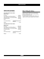
SPECIFICATIONS
SPECIFICATIONS
UL® 1008 Listed Transfer Switch
Model 071014
Enclosure . . . . . . . . . . . . . . . . . . . . . . . . . . . .NEMA 1
Utility Supply Circuit Breaker Rating . . . . . . .50 Amps
Generator Supply Circuit Breaker Rating . . .30 Amps
Rated AC Voltage . . . . . . . . . . . . . . . . . . . . .250 Volts
Poles . . . . . . . . . . . . . . . . . . . . . . . . . . . . . . . . . . . . .2
Fault Current Rating . . . . . .10,000 RMS Symmetrical
Amperes
Weight . . . . . . . . . . . . . . . . . . . . . . . . . . . . . . . .27 lbs.
UL® 1008 Listed Transfer Switch
Model 071017
Enclosure . . . . . . . . . . . . . . . . . . . . . . . . . . .NEMA 3R
Utility Supply Circuit Breaker Rating . . . . . . .50 Amps
Generator Supply Circuit Breaker Rating . . .30 Amps
Rated AC Voltage . . . . . . . . . . . . . . . . . . . . .250 Volts
Poles . . . . . . . . . . . . . . . . . . . . . . . . . . . . . . . . . . . . .2
Fault Current Rating . . . . . .10,000 RMS Symmetrical
Amperes
Weight . . . . . . . . . . . . . . . . . . . . . . . . . . . . . . . .34 lbs.
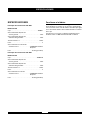
When Calling the Factory
Before contacting Briggs and Stratton Power Products
regarding service or repair of this transfer switch,
obtain the Model Number from the unit data decal
located on or inside the case.
To contact Briggs and Stratton Power Products call
1-800-743-4115, between 8:00 AM and 5:00 PM CT.

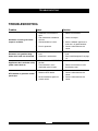
TROUBLESHOOTING
15
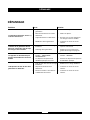
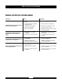
Problem Cause Solution
Generator is running, but no AC
output is available.
1. Generator circuit breaker is
open.
2. Poor connection or defective
cord set.
3. Connected device is bad.
4. Fault in generator.
1. Reset circuit breaker.
2. Check and repair.
3. Select a different appliance or
load that is in good condition.
4. Contact authorized service
center.
Generator runs good but bogs
down when loads are connected.
1. Short circuit in a connected
load.
2. Generator is overloaded.
1. Disconnect shorted electrical
load.
2. See “Load Management” on page
13.
Appliances don’t work after utility
power comes back on.
1. Transfer switch in GENERATOR
position.
2. Circuit breaker in main
distribution panel is open.
1. Set switch to UTILITY position.
2. Reset circuit breaker in main
distribution panel.
GFCI breaker in generator control
panel trips.
1. Ground fault in connected load.
2. Defective GFCI device.
3. Neutral bonded to ground in
transfer switch.
1. Remove load with fault.
2. Contact authorized service
center.
3. Contact authorized service
center.
TROUBLESHOOTING

SERVICE PARTS
16
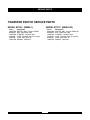
TRANSFER SWITCH SERVICE PARTS
MODEL 071014 (NEMA 1)
Part # Description
198414GS SWITCH, MNL, Transfer, NEMA 1
B3298GS BOX, Connection, 30A
198415GS CORDSET, 125/250V, 30A
43438GS PLUG, 125/250V, 30A, 4P Locking
43483GS PLUG, 250V, 20A, 4P
198417GS MANUAL, Operator’s
MODEL 071017 (NEMA 3R)
Part # Description
201031GS SWITCH, MNL, Transfer, NEMA 3R
B3298GS BOX, Connection, 30A
198415GS CORDSET, 125/250V, 30A
43438GS PLUG, 125/250V, 30A, 4P Locking
43483GS PLUG, 250V, 20A, 4P
198417GS MANUAL, Operator’s

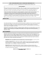
BRIGGS & STRATTON POWER PRODUCTS GROUP, LLC TRANSFER SWITCH OWNER WARRANTY POLICY
LIMITED WARRANTY
Briggs & Stratton Power Products Group, LLC will repair or replace, free of charge, any part(s) of the equipment that is defective
in material or workmanship or both. Transportation charges on product submitted for repair or replacement under this warranty
must be borne by purchaser. This warranty is effective for the time periods and subject to the conditions stated below. For
warranty service, find the nearest Authorized Service Dealer in our dealer locator map at BRIGGSandSTRATTON.com.
THERE IS NO OTHER EXPRESS WARRANTY. IMPLIED WARRANTIES, INCLUDING THOSE OF MERCHANTABILITY AND
FITNESS FOR A PARTICULAR PURPOSE, ARE LIMITED TO ONE YEAR FROM PURCHASE, OR TO THE EXTENT
PERMITTED BY LAW ANY AND ALL IMPLIED WARRANTIES ARE EXCLUDED. LIABILITY FOR INCIDENTAL OR
CONSEQUENTIAL DAMAGES ARE EXCLUDED TO THE EXTENT EXCLUSION IS PERMITTED BY LAW. Some states or
countries do not allow limitations on how long an implied warranty lasts, and some states or countries do not allow the exclusion
or limitation of incidental or consequential damages, so the above limitation and exclusion may not apply to you. This warranty
gives you specific legal rights and you may also have other rights which vary from state to state or country to country.
3 years
None
Consumer Use
Commercial Use
The warranty period begins on the date of purchase by the first retail consumer or commercial end user, and continues for the period
of time stated in the table above. “Consumer use" means personal residential household use by a retail consumer. “Commercial use"
means all other uses, including use for commercial, income producing or rental purposes. Once equipment has experienced
commercial use, it shall thereafter be considered as commercial use for purposes of this warranty. Equipment used for prime power
in place of utility are not applicable to this warranty.
NO WARRANTY REGISTRATION IS NECESSARY TO OBTAIN WARRANTY ON BRIGGS & STRATTON PRODUCTS. SAVE YOUR
PROOF OF PURCHASE RECEIPT. IF YOU DO NOT PROVIDE PROOF OF THE INITIAL PURCHASE DATE AT THE TIME
WARRANTY SERVICE IS REQUESTED, THE MANUFACTURING DATE OF THE PRODUCT WILL BE USED TO DETERMINE THE
WARRANTY PERIOD.
ABOUT YOUR WARRANTY
We welcome warranty repair and apologize to you for being inconvenienced. Any Authorized Service Dealer may perform warranty
repairs. Most warranty repairs are handled routinely, but sometimes requests for warranty service may not be appropriate. For
example, warranty service would not apply if equipment damage occurred because of misuse, lack of routine maintenance, shipping,
handling, warehousing or improper installation. Similarly, the warranty is void if the manufacturing date or the serial number on the
equipment has been removed or the equipment has been altered or modified. During the warranty period, the Authorized Service
Dealer, at its option, will repair or replace any part that, upon examination, is found to be defective under normal use and service.
This warranty will not cover the following repairs and equipment:
• Normal Wear: Outdoor Power Equipment, like all mechanical devices, needs periodic parts and service to perform well. This
warranty does not cover repair when normal use has exhausted the life of a part or the equipment.
• Installation and Maintenance: This warranty does not apply to equipment or parts that have been subjected to improper or
unauthorized installation or alteration and modification, misuse, negligence, accident, overloading, improper maintenance,
repair or storage so as, in our judgment, to adversely affect its performance and reliability. This warranty also does not cover
normal maintenance such as adjustments, cleaning and fuse replacement.
• Other Exclusions: This warranty excludes wear items or damage or malfunctions resulting from accidents, abuse,
modifications, alterations, or improper servicing. Accessory parts are excluded from the product warranty. This warranty
excludes failures due to acts of God and other force majeure events beyond the manufacturers control. Also excluded is used,
reconditioned, and demonstration equipment.
BRIGGS & STRATTON POWER PRODUCTS GROUP, LLC
JEFFERSON, WI, USA
Effective November 1, 2005 replaces all undated Warranties and all Warranties dated before November 1, 2005
198180E, Rev. B, 7/14/2006
WARRANTY PERIOD

TABLE DES MATIÈRES
18
TABLE DES MATIÈRES
TABLE DES MATIÈRES. . . . . . . . . . . . . . . . . . . . . . . . . . . 18
DIRECTIVES DE SÉCURITÉ IMPORTANTES . . . . . . . . . 19
INTRODUCTION . . . . . . . . . . . . . . . . . . . . . . . . . . . . . . . . 20
Pour le propriétaire résidentiel . . . . . . . . . . . . . . . . . . 20
Au détaillant/à l’entrepreneur procédant à l’installation20
Orientation du propriétaire . . . . . . . . . . . . . . . . . . . . . 21
Responsabilités de l’installateur . . . . . . . . . . . . . . . . . 21
Description de l’équipement . . . . . . . . . . . . . . . . . . . . 21
Génératrices compatibles. . . . . . . . . . . . . . . . . . . . . . 21
INSTALLATION . . . . . . . . . . . . . . . . . . . . . . . . . . . . . . . . . 22
Déballage . . . . . . . . . . . . . . . . . . . . . . . . . . . . . . . . . . 22
Vérification de la livraison . . . . . . . . . . . . . . . . . . 22
Directives d’assemblage. . . . . . . . . . . . . . . . . . . . . . . 23
ISOLATION DES CIRCUITS ESSENTIELS . . . . . . . . . . . 24
Interconnexions du câblage d’alimentation. . . . . . . . . . 25-26
Boîte d’entrée. . . . . . . . . . . . . . . . . . . . . . . . . . . . . 27-28
Cordons de raccordement. . . . . . . . . . . . . . . . . . 28
UTILISATION DU SYSTÈME . . . . . . . . . . . . . . . . . . . . . . . 29
Gestion des charges. . . . . . . . . . . . . . . . . . . . . . . . . . 29
SPÉCIFICATIONS. . . . . . . . . . . . . . . . . . . . . . . . . . . . . . . 30
Modèle 071014 . . . . . . . . . . . . . . . . . . . . . . . . . . 30
Modèle 071017 . . . . . . . . . . . . . . . . . . . . . . . . . . 30
Si vous téléphonez au manufacturier . . . . . . . . . . . . . 30
DÉPANNAGE. . . . . . . . . . . . . . . . . . . . . . . . . . . . . . . . . . . 31
REMARQUES . . . . . . . . . . . . . . . . . . . . . . . . . . . . . . . . . . 32
GARANTIE. . . . . . . . . . . . . . . . . . . . . . . . . . . . . . . . . . . . . 33

DIRECTIVES DE SÉCURITÉ IMPORTANTES
19
DIRECTIVES DE SÉCURITÉ
IMPORTANTES
Voici le symbole utilisé pour les avertissements
de sécurité. Il est utilisé pour vous avertir des
dangers possibles de blessure. Respectez tous
les messages de sécurité qui suivent ce symbole
pour éviter des blessures ou des décès.
Le symbole d’avertissement de sécurité ( ) est utilisé avec
un mot signal (DANGER, MISE EN GARDE,
AVERTISSEMENT), une image et/ou un message de
sécurité vous avertissant des risques. Le mot DANGER
indique un danger qui, s’il n’est pas évité, causera la mort ou
des blessures graves. Le mot AVERTISSEMENT indique un
risque qui, s’il n’est pas évité, pourrait causer la mort ou des
blessures graves. Le terme MISE EN GARDE indique un
risque qui, s’il n’est pas évité, pourrait causer des blessures
mineures ou modérées. Le terme REMARQUE, utilisé sans
pictogramme de sécurité, indique une situation qui pourrait
causer des dommages à l’équipement. Suivez les directives
des messages de sécurité pour éviter ou réduire les risques
de blessures ou de décès.
Le fabricant ne peut anticiper toutes les circonstances
potentielles pouvant comporter un danger. Par conséquent,
les avertissements contenus dans le présent manuel, ainsi
que les plaques et les décalques apposés sur l’unité
n’englobent pas toutes les possibilités. Si vous utilisez une
procédure, une méthode de travail ou une technique
d’opération non spécifiquement recommandée par le
fabricant, vous devez vous assurer qu’elle ne compromet
pas votre sécurité ni celle des autres. Vous devez également
vous assurer que la procédure, la méthode de travail ou la
technique d’opération que vous choisissez ne rende pas le
commutateur de transfert dangereux.
CONSERVEZ CES DIRECTIVES
• NE PAS toucher aux fils dénudés ou aux prises.
• NE PAS utiliser le commutateur de transfert si le câblage est
usé, effiloché, dénudé ou autrement endommagé.
• NE PAS manipuler les fils électriques les pieds dans l’eau ou les
pieds nus ou lorsque les mains ou les pieds sont mouillés.
• Si vous devez travailler autour d’une unité alors qu’elle est en
marche, placez-vous sur une surface sèche isolée afin de
réduire les risques de choc électrique.
• NE PAS laisser les personnes non qualifiées ou les enfants
opérer ou entretenir le commutateur de transfert.
• En cas d’accident causé par un choc électrique, procédez
immédiatement à la mise hors tension de l’alimentation
électrique et communiquez avec les autorités locales. Évitez
tout contact direct avec la victime.
Si le commutateur n’est pas mis à la terre
comme il se doit, il y a risque d’électrocution.
AVERTISSEMENT
• Utilisez le commutateur de transfert seulement pour les
utilisations pour lesquelles il est conçu.
• Si vous avez des questions à propos de l’utilisation prévue de
cet appareil, consultez votre détaillant ou communiquez avec
Briggs and Stratton Power Products.
• Ne pas exposer le commutateur de transfert à l’humidité
excessive, à la poussière, aux saletés ou aux vapeurs
corrosives.
• Demeurez alerte en tout temps lorsque vous travaillez sur cet
équipement. Ne travaillez jamais sur l’équipement si vous êtes
fatigué physiquement ou mentalement.
• Si les appareils branchés surchauffent, éteignez-les et mettez
leur disjoncteur ou fusible hors tension.
Le traitement inadéquat du commutateur de transfert
peut l’endommager et réduire sa durée de vie utile.
REMARQUE
• En dépit de la conception sécuritaire du commutateur, le fait
d’opérer l’équipement de façon imprudente, de ne pas
l’entretenir ou d’être négligent peut causer des blessures et la
mort.
Le commutateur de transfert contient une tension
dangereuse qui peut causer des blessures
personnelles ou la mort.
AVERTISSEMENT
• Un électricien autorisé doit effectuer l’installation du
commutateur de transfert.
• Conformez-vous aux normes, réglementations et aux codes
fédéraux, provinciaux et locaux applicables.
Tout contact avec les pièces sous tension peut
causer un choc électrique ou des brûlures.
AVERTISSEMENT

INTRODUCTION
20
INTRODUCTION
Nous vous remercions d’avoir acheté le commutateur
neutre de transfert manuel de Briggs & Stratton. Ce
commutateur est conçu pour être utilisé avec des
génératrices avec ou sans disjoncteurs de fuite de terre
(GFCI). Le commutateur débranche le circuit neutre
approproié de sorte que le disjoncteur de fuite de terre puisse
fonctionner correctement.
Ce commutateur est conçu pour être utilisé avec une
génératrice résidentielle auxiliaire fournissant une source
d’électricité de rechange et pouvant alimenter une fournaise
au gaz, les systèmes de réfrigération et les systèmes de
communication qui, lorsqu’ils sont arrêtés durant une panne
d’électricité, peuvent causer de l’inconfort ou d’autres
désagréments. Ce produit ne se qualifie PAS comme
génératrice d’urgence tel que défini par la NFPA 70 (NEC).
La société Briggs & Stratton Power Products a tout fait pour
fournir un produit dont l’installation soit sécuritaire, facile et
économique. Comme chaque installation est unique, il est
impossible de connaître et de recommander une marche à
suivre présentant toutes les méthodes et consignes
d’installation possibles. Briggs et Stratton ignore également
les dangers et/ou les résultats potentiels de chaque méthode
ou procédure. C’est pourquoi
Seulement un électricien autorisé devrait installer ce
commutateur. Toute installation doit être conforme à
tous les codes, normes et à la réglementation
applicables (fédéraux, provinciaux et locaux).
Votre commutateur de transfert BSPP est livré avec le
présent « Guide d’installation et d’utilisation ». Ce guide est
un document important; conservez-le après avoir complété
l’installation.
Tout a été fait pour s’assurer que les renseignements
contenus dans le présent guide soient exacts et à jour.
Toutefois, le fabriquant se réserve le droit de changer, de
modifier ou encore d’améliorer le système en tout temps, et
ce, sans préavis.
Pour le propriétaire résidentiel
Afin de vous aider à faire des choix avisés et à communiquer
efficacement avec l’entrepreneur qui procédera à
l’installation,
Veuillez lire avec soin la section « Conseils au
propriétaire » dans le présent guide avant de contracter
un entrepreneur ou de commencer l’installation de votre
commutateur de transfert.
Pour assurer une installation adéquate, veuillez contacter le
magasin qui vous a vendu votre commutateur de transfert
Briggs & Stratton, votre détaillant ou votre fournisseur de
services d’électricité.
Si l’installation du commutateur n’est pas effectuée
par un professionnel en électricité certifié,
sa garantie sera ANNULÉE.
Au détaillant/à l’entrepreneur procédant à
l’installation
• Vérifiez les codes fédéraux, provinciaux et locaux si vous
avez des questions concernant l’installation.
• Pour de plus amples renseignements sur le commutateur
de transfert, téléphonez au1-800-743-4115, de 8h à
17h heure du Centre.
La page est en cours de chargement...
La page est en cours de chargement...
La page est en cours de chargement...
La page est en cours de chargement...
La page est en cours de chargement...
La page est en cours de chargement...
La page est en cours de chargement...
La page est en cours de chargement...
La page est en cours de chargement...
La page est en cours de chargement...
La page est en cours de chargement...
La page est en cours de chargement...
La page est en cours de chargement...
La page est en cours de chargement...
La page est en cours de chargement...
La page est en cours de chargement...
La page est en cours de chargement...
La page est en cours de chargement...
La page est en cours de chargement...
La page est en cours de chargement...
La page est en cours de chargement...
La page est en cours de chargement...
La page est en cours de chargement...
La page est en cours de chargement...
La page est en cours de chargement...
La page est en cours de chargement...
La page est en cours de chargement...
La page est en cours de chargement...
-
 1
1
-
 2
2
-
 3
3
-
 4
4
-
 5
5
-
 6
6
-
 7
7
-
 8
8
-
 9
9
-
 10
10
-
 11
11
-
 12
12
-
 13
13
-
 14
14
-
 15
15
-
 16
16
-
 17
17
-
 18
18
-
 19
19
-
 20
20
-
 21
21
-
 22
22
-
 23
23
-
 24
24
-
 25
25
-
 26
26
-
 27
27
-
 28
28
-
 29
29
-
 30
30
-
 31
31
-
 32
32
-
 33
33
-
 34
34
-
 35
35
-
 36
36
-
 37
37
-
 38
38
-
 39
39
-
 40
40
-
 41
41
-
 42
42
-
 43
43
-
 44
44
-
 45
45
-
 46
46
-
 47
47
-
 48
48


Simplicity 040434-00 Manuel utilisateur
- Catégorie
- Groupes électrogènes
- Taper
- Manuel utilisateur
dans d''autres langues
- English: Simplicity 040434-00 User manual
- español: Simplicity 040434-00 Manual de usuario