Peerless SC551GL Manuel utilisateur
- Catégorie
- Chariots multimédia
- Taper
- Manuel utilisateur


2 of 35 ISSUED: 02-25-11 SHEET #: 009-9050-4 06-16-14
NOTE: Read entire instruction sheet before you start installation and assembly.
Table of Contents
Parts List............................................................................................................................................................................ 3, 4
Attaching Glass Base .............................................................................................................................................................5
Attaching Glass Shelf .............................................................................................................................................................6
Installing Universal Adapter Plate to Display ..........................................................................................................................8
Mounting Flat Panel Display ................................................................................................................................................ 10
Tools Needed for Assembly
• level
• phillips screwdriver
• Do not begin to install your Peerless product until you have read and understood the instructions and warnings
contained in this Installation Sheet. If you have any questions regarding any of the instructions or warnings, for US
customers please call Peerless customer care at 1-800-865-2112, for all international customers, please contact
your local distributor.
• This product should only be installed by someone of good mechanical aptitude, and fully understands
these instructions.
• Never exceed the maximum load capacity on page one.
• Always use an assistant or mechanical lifting equipment to safely lift and position equipment.
• Tighten screws fi rmly, but do not overtighten. Overtightening can damage the items, greatly reducing their holding
power.
• The cart is not affi xed or secured to the fl oor, and may therefore tip over and/or fall if display and/or stand is shaken
or hit. Always monitor children and do not let children play alone around stand as they could get hurt by a falling
display. Not recommended for use in areas with heavy traffi c.
• Do not stand on tempered glass
• This product is intended for indoor use only. Use of this product outdoors could lead to product failure and personal
injury.
WARNING

3 of 35 ISSUED: 02-25-11 SHEET #: 009-9050-4 06-16-14
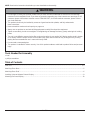
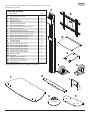
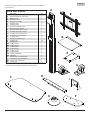
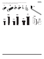
Before you begin, make sure all parts shown are included with your product.
Description Qty.
Acolumn assembly 1
Buniversal adapter plate 1
Cglass base 1
Dglass shelf 1
Eshelf bracket 1
Ffront caster 2
Grear caster 2
Hrear caster support plate 1
Icolumn cover 1
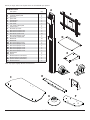
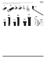
Kflat head cap screw 4
LM6 x 15mm socket screw 4
MM8 x 30mm socket screw 2
NM6 x 8mm socket screw 16
OM5 x 12mm phillips screw 2
Pfront caster support plate 2
QM6 washer 20
RM8 washer 2
AA M5 x 15mm philips screw 4
BB M5 x 35mm phillips screw 4
CC M6 x 15mm phillips screw 4
DD M6 x 35mm phillips screw 4
EE M8 x 15mm phillips screw 4
FF M8 x 35mm phillips screw 4
GG Multiwasher 4
HH spacer 4
II M4 allen wrench (not shown) 1
JJ M5 allen wrench (not shown) 1
K
K
spanner wrench (not shown) 1
LL M3 allen wrench 1
Parts List
C
D
E
AB
HI
K
Parts may appear slightly different than illustrated. FG
P

4 of 35 ISSUED: 02-25-11 SHEET #: 009-9050-4 06-16-14
RLL
OQ
N
LM
Before you begin, make sure all parts shown are included with your product.
Parts may appear slightly different than illustrated.
AA
BB GG
HH
CC
DD
EE
FF

5 of 35 ISSUED: 02-25-11 SHEET #: 009-9050-4 06-16-14
A
M
R
C
H
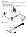
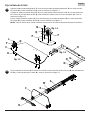
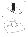
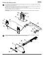
Attach column assembly (A) to glass base (C) with two M8 x 30mm screws (M), two M8 washers (R) and rear
caster support bar (H).
2
Attach front casters (F) to front caster plates (P) with four M6 x 8mm screws (N) and four M6 washers (Q) as
shown in fi gure 1.1.
Attach front casters (F) to front of glass base (C) with two M6 x 15mm screws (L), two M6 washers (Q), and two
fl at head cap screws (K) as shown in fi gure 1.2.
Attach rear casters (G) to caster plate (H) with four M6 x 8mm screws (N) and four M6 washers (Q) as shown in
fi gure 1.3.
NOTE: Lock brakes on casters, for no sudden movements during installation.
1
L
H
G
Q
Q
P
N
N
F
F
Q
C
K
fi g. 1.3
fi g. 1.2
Attaching Glass Base
fi g. 1.1

6 of 35 ISSUED: 02-25-11 SHEET #: 009-9050-4 06-16-14
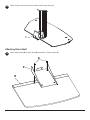
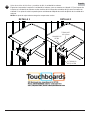
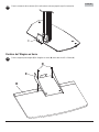
Attach column cover (I) onto rear of column until it snaps into place.
Attach shelf bracket (E) to glass shelf (D) with two M5 x 12mm screws (O).
3
4
Attaching Glass Shelf
I
O
E
D

7 of 35 ISSUED: 02-25-11 SHEET #: 009-9050-4 06-16-14
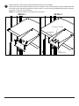
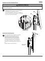
DETAIL 1 DETAIL 2
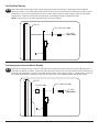
Remove two M4 x 8mm screws and two M4 washers from column assembly.
Hook shelf bracket onto column assembly as shown in detail 1. Secure shelf bracket to column assembly with two
M4 x 8mm screws and two M4 washers as shown in detail 2. Glass shelf may be adjusted vertically by loosening
set screws on front of column assembly.
NOTE: Do not adjust shelf while components are on the shelf.
5
M4 WASHER
SET SCREW
M4 x 8mm SCREW

8 of 35 ISSUED: 02-25-11 SHEET #: 009-9050-4 06-16-14
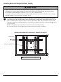
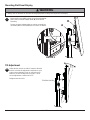
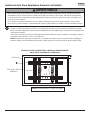
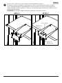
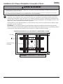
To prevent scratching the display, set a cloth on a fl at, level surface that will support the weight of the display.
Place display face side down and refer to display manufacturer's instructions for removing obstructions from the
back of the display. Adjust display brackets of universal adapter plate (B) to align with display mounting holes.
Select the screws from the baffl ed fastener pack that best fi t your display and secure to display following step 6-1
or 6-2 on page 9.
NOTE: Top and bottom mounting holes must be used for attaching display brackets.
Verify that all holes are properly aligned, then tighten screws using a phillips screwdriver.
6
Installing Universal Adapter Plate to Display
CENTER DISPLAY BRACKETS VERTICALLY ON BACK OF DISPLAY
DISPLAY
DISPLAY BRACKETS
NOTE: "X" dimensions should be equal.
X
X
• Tighten screws so display brackets are fi rmly attached to display. Do not tighten with excessive force.
Overtightening can cause stress damage to screws, greatly reducing their holding power and possibly causing
screw heads to become detached. Tighten to 40 in. • lb (4.5 N.M.) maximum torque.
• If screws don't get three complete turns in the display inserts or if screws bottom out and bracket is still not tightly
secured, damage may occur to display or product may fail.
WARNING
B

9 of 35 ISSUED: 02-25-11 SHEET #: 009-9050-4 06-16-14
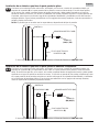
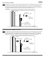
Begin with the shortest length screw, hand thread screw through multi-washer and display brackets (B) into
display as shown. Screw must make at least three full turns into the mounting hole and fi t snug into place. Do not
overtighten. If screw cannot make three full turns into the display, select a longer length screw from the baffl ed
fastener pack. Repeat for remaining mounting holes, level display brackets and tighten screws.
NOTE: Spacers may not be used, depending upon the type of display.
Begin with the longest length screw, hand thread screw through multi-washer, display brackets (B) and spacer in
that order into display as shown. Screw must make at least three full turns into the mounting hole and fi t snug into
place. Do not overtighten. If screw cannot make three full turns into the display, select a shorter length screw from
the baffl ed fastener pack. Repeat for remaining mounting holes, level display brackets and tighten screws.
For Flat Back Display
For Bump-out or Recessed Back Display
6-1
6-2
DISPLAY
DISPLAY
MULTI-WASHER (GG)
MULTI-WASHER (GG)
SCREW
SCREW
(AA,CC,EE)
(BB,DD,FF)
B
B
SPACER (HH)

10 of 35 ISSUED: 02-25-11 SHEET #: 009-9050-4 06-16-14
Mounting Flat Panel Display
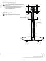
Tilt Adjustment
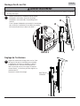
Remove M8 nut and M8 washer from universal adapter
plate. Hook universal adapter plate (B) onto column
assembly.
Secure universal adapter plate to column assembly by
reinstalling M8 nut and M8 washer as shown in detail 3.
7B
A
Adjust tension knobs on sides of mount to desired
tension to enable tilt adjustment and balance your
screen size and weight. Push or pull from top or
bottom of screen to adjust tilt as shown. The tilt
can be adjusted to a maximum of 15°.
Retighten tension knob.
8
• Always use an assistant or mechanical lifting equipment to safely lift and position the display.
WARNING
DETAIL 3
M8 NUT M8 WASHER
TENSION KNOB

11 of 35 ISSUED: 02-25-11 SHEET #: 009-9050-4 06-16-14
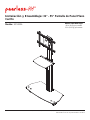
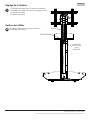
Vertical Height Adjustment
Cable Management
Inner column should adjust up and down without using
knobs or tools.
If more or less tension is required, tighten or loosen
knob on rear of mount, adjust column to desired
position, and retighten knob.
9
Cables may be routed through inner channel of
column.
10
INNER CHANNEL
CABLE
HEIGHT
ADJUSTMENT
KNOB
© 2011, Peerless Industries, Inc. All rights reserved.
All other brand and product names are trademarks or registered trademarks of their respective owners.

2300 White Oak Circle • Aurora, Il 60502 • (800) 865-2112 • Fax: (800) 359-6500 • www.peerlessmounts.com
PUBLICADO: 02-25-11 HOJA #: 009-9050-4 06-16-14
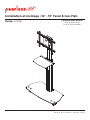
Instalación y Ensamblaje: 32" - 55" Pantalla de Panel Plano
Carrito
Modelo: SC551GL Máxima capacidad carga:
66 lb (30 kg) por pantalla
25 lb (11.3 kg) por estante

PUBLICADO: 02-25-11 HOJA #: 009-9050-4 06-16-14
13 de 35
NOTA: Lea toda la hoja de instrucciones antes de iniciar la instalación y el montaje.
Tabla de contenido
Lista de piezas................................................................................................................................................................ 14,15
Fijar la base de cristal.......................................................................................................................................................... 16
Fijar la repisa de cristal........................................................................................................................................................ 17
Instalación de la placa adaptadora universal a la pantalla .................................................................................................. 19
Instalación de la pantalla plana ........................................................................................................................................... 21
Herramientas necesarias para el ensamblaje
• nivel
• destornillador phillips
• No comience a instalar su producto de Peerless hasta haber leído y entendido las instrucciones y las advertencias
contenidas en la Hoja de Instalación. Si tiene alguna pregunta acerca de cualquiera de las instrucciones o las
advertencias, por favor, llame a Servicio al Cliente de Peerless al 1-800-865-2112 si está en EE. UU. Si es un
cliente internacional, por favor, comuníquese con su distribuidor local.
• Este producto sólo debe ser instalado por una persona que tenga una buena aptitud mecánica, que tenga
experiencia en construcción básica de edifi cios y que entienda estas instrucciones en su totalidad.
• Nunca sobrepase la capacidad máxima de soportar carga. Vea la página 12.
• Siempre cuente con la ayuda de un asistente o utilice un equipo mecánico de izar para levantar y colocar el equipo
con más seguridad.
• Apriete los tornillos con fi rmeza, pero no en exceso. Apretarlos en exceso puede dañar los artículos y puede
disminuir signifi cativamente su fuerza de fi jación.
• El carrito no está anclado ni fi jado al suelo y, por lo tanto, podría volcarse o caerse si la pantalla o el estante
reciben una sacudida o un golpe. Vigile siempre a los niños y no los deje jugar solos cerca del estante, ya que
podrían lastimarse si se cae la pantalla. No se recomienda para uso en áreas de mucho tránsito.
• Este producto está diseñado para uso en interiores solamente. Utilizar este producto en exteriores podría causar
fallas del producto y lesiones a individuos.
ADVERTENCIA
Español

PUBLICADO: 02-25-11 HOJA #: 009-9050-4 06-16-14
14 de 35
Español
Antes de comenzar, coteje la lista de piezas para asegurarse de que se han
incluido todas las piezas.
D
E
B
Las piezas pueden verse un poco distintas a la ilustración.
Descripción Cant.
AUnidad de la columna 1
BPlaca adaptadora universal 1
CBase de cristal 1
DRepisa de cristal 1
ESoporte para repisas 1
FRueda pivotante delantera 2
GRueda pivotante trasera 2
Hplaca de apoyo para ruedas pivotantes 1
ICubierta de la columna 1
Lista de Piezas
KBarra de apoyo de la columna 4
Ltornillos de cabeza hueca de M6 x 15mm 4
Mtornillos de cabeza hueca de M8 x 30mm 2
Ntornillos de cabeza hueca de M6 x 8mm 16
Otornillos phillips de M5 x 12mm 2
Pplaca rueda pivotante delantera 2
Qarandelas de M6 20
Rarandelas de M8 2
AA tornillos phillips de M5 x 15mm 4
BB tornillos phillips de M5 x 35mm 4
CC tornillos phillips de M6 x 15mm 4
DD tornillos phillips de M6 x 35mm 4
EE tornillos phillips de M8 x 15mm 4
FF tornillos phillips de M8 x 35mm 4
GG arandela múltiple 4
HH espaciador 4
II Llave M4 (no se muestra) 1
JJ Llave M5 (no se muestra) 1
K
K
Llave inglesa (no se muestra) 1
LL Llave allen M3 1
C
A
HI
K
FG
P

PUBLICADO: 02-25-11 HOJA #: 009-9050-4 06-16-14
15 de 35
Español
Antes de comenzar, coteje la lista de piezas para asegurarse de que se han incluido todas las piezas.
Las piezas pueden verse un poco distintas a la ilustración.
AA
BB GG
HH
CC
DD
EE
FF
RLL
OQ
N
LM

PUBLICADO: 02-25-11 HOJA #: 009-9050-4 06-16-14
16 de 35
Español
Fije la unidad de la columna (A) en la base de cristal (C) con dos tornillos de M8 x 30 mm (M), dos arandelas de
M8 (R) y la barra de apoyo de la base (H), como se muestra en la fi gura 2.1.
2
A
M
R
C
H
Adjuntar ruedas pivotantes delanteras (F) a las placas de ruedas pivotantes delanteras (P) con cuatro tornillos
M6 x 8mm (N) y cuatro arandelas M6 (Q), como se muestra en la fi gura 1.1
Coloque las ruedas pivotantes delanteras (F) en la parte delantera de la base de cristal (C) con dos tornillos de
M6 x 15mm (L), dos arandelas de M6 (Q) y dos tornillos de cabeza plana con hueco hexagonal (K), como se
muestra en la fi gura 1.2.
Fije las ruedas pivotantes traseras (G) en la placa de apoyo para ruedas pivotantes (H) con cuatro tornillos de
M6 x 8mm (N) y cuatro arandelas de M6 (Q), como se muestra en la fi gura 1.3.
NOTA: Trabe los frenos de las ruedas pivotantes para evitar los movimientos repentinos durante la instalación.
1
Fijar la Base de Cristal
L
H
G
Q
Q
P
N
N
F
F
Q
C
Kfi g. 1.3
fi g. 1.2
fi g. 1.1

PUBLICADO: 02-25-11 HOJA #: 009-9050-4 06-16-14
17 de 35
Español
Presione la cubierta de la columna (I) sobre la parte trasera de la columna hasta que entre en su lugar.
Fije el soporte de la repisa (E) en la repisa de cristal (D) con dos tornillos de M5 x 12mm (O).
3
4
Fijar la Repisa de Cristal
I
O
E
D

PUBLICADO: 02-25-11 HOJA #: 009-9050-4 06-16-14
18 de 35
Español
EL TORNILLO
DE FIJACIÓN
DETALLE 1 DETALLE 2
5Quite dos tornillos de M4 x 8mm y arandelas de M4, de unidad de la columna.
Enganche el soporte de la repisa en la unidad de la columna, como se muestra en el detalle 1. Fije el soporte de
la repisa en la unidad de la columna con dos tornillos de M4 x 8mm dos arandelas de M4, como se muestra en
el detalle 2. La repisa de cristal se puede ajustar verticalmente afl ojando las tornillo de fi jación de la unidad de la
columna.
NOTA: No ajuste la repisa mientras tenga los componentes encima.
ARANDELAS
DE M4
TORNILLOS
M4 x 8mm

PUBLICADO: 02-25-11 HOJA #: 009-9050-4 06-16-14
19 de 35
Español
Para no rayar la pantalla, coloque un trapo sobre una superfi cie plana y nivelada que sostenga el peso de la
pantalla. Coloque la pantalla boca abajo. Si la pantalla tiene perillas en la parte trasera, quíteselas para poder
fi jar los soportes adaptadores. Ajuste los placa adaptadora universal (B) para que se alineen con los agujeros de
montaje de la pantalla
Seleccione los tornillos de sujeción del paquete de desconcertado que mejor se adapten a la pantalla y seguro a
la pantalla siguiente paso 6-1 o 6-2 en la página 20.
NOTA: Asegúrese de que fi ja los soportes con los mangos hacia fuera, como se muestra abajo. Verifi que que
todos los agujeros estén debidamente alineados y luego apriete los tornillos usando un destornillador phillips.
6
Instalación de la Placa Adaptadora Universal a la Pantalla
CENTRALICE LOS SOPORTES DE LA PANTALLA VERTICALMENTE
EN LA PARTE TRASERA DE LA PANTALLA
PANTALLA
SOPORTES DE LA
PANTALLA
NOTA: Las dimensiones "X" deben ser iguales.
X
X
B
• Apriete los tornillos de tal modo que los soportes adaptadores queden fi rmemente sujetos. No apriete aplicando
demasiada fuerza. El apriete excesivo puede causar daño por esfuerzo a los tornillos, reduciendo enormemente
su fuerza de fi jación y causando el posible desprendimiento de sus cabezas. Apriete los tornillos a 40 pulg-lb (4.5
N•m) de par torsor máximo.
• Si los tornillos no pueden atornillarse con tres vueltas completas en los insertos de la pantalla, o si los tornillos
topan fondo y la placa todavía no está fi rmemente sujeta, se podría dañar la pantalla o causar la falla del producto.
ADVERTENCIA

PUBLICADO: 02-25-11 HOJA #: 009-9050-4 06-16-14
20 de 35
Español
Comience con uno de los tornillos más cortos, enrósquelo, con la mano, a través de la arandela múltiple y el
soportes de la pantalla (B) a la parte posterior de la pantalla, como se muestra abajo. El tornillo tiene que dar,
por lo menos, tres vueltas completas dentro del agujero de montaje y debe quedar ajustado en su lugar. No
apriete los tornillos en exceso. Si el tornillo no puede dar tres vueltas completas al entrar en la parte posterior de
la pantalla, seleccione un tornillo más largo de los sujetadores identifi cados y clasifi cados en las divisiones del
empaque plástico. Siga el mismo procedimiento con los agujeros de montaje restantes, nivele los soportes de la
pantalla y apriete los tornillos.
NOTA: Es posible que no necesite usar los espaciadores, dependiendo del tipo de pantalla.
Comience con uno de los tornillos más largos, enrósquelo, con la mano, a través de la arandela múltiple, los
soportes de la pantalla (B) y el espaciador, en ese orden, a la parte posterior de la pantalla, como se muestra
abajo. El tornillo tiene que dar, por lo menos, tres vueltas completas dentro del agujero de montaje y debe quedar
ajustado en su lugar. No apriete los tornillos en exceso. Si el tornillo no puede dar tres vueltas completas al entrar
en la parte posterior de la pantalla, seleccione un tornillo más largo de los sujetadores identifi cados y clasifi cados
en las divisiones del empaque plástico. Siga el mismo procedimiento con los agujeros de montaje restantes,
nivele los soportes de la pantalla y apriete los tornillos.
Instalación de un televisor que tiene la parte posterior plana
Instalación de un televisor que tiene la parte posterior abultada o empotrada
6-1
6-2
PANTALLA
PANTALLA
ARANDELA MÚLTIPLE (GG)
ARANDELA MÚLTIPLE (GG)
TORNILLO
(AA,CC,EE)
PLACA ADAPTADORA
UNIVERSAL (B)
ESPACIADOR (HH)
PLACA ADAPTADORA
UNIVERSAL (B)
Si tiene alguna pregunta, por favor, llame a Servicio al Cliente de Peerless al 1-800-865-2112.
Si tiene alguna pregunta, por favor, llame a Servicio al Cliente de Peerless al 1-800-865-2112.
TORNILLO
(BB,DD,FF)
La page est en cours de chargement...
La page est en cours de chargement...
La page est en cours de chargement...
La page est en cours de chargement...
La page est en cours de chargement...
La page est en cours de chargement...
La page est en cours de chargement...
La page est en cours de chargement...
La page est en cours de chargement...
La page est en cours de chargement...
La page est en cours de chargement...
La page est en cours de chargement...
La page est en cours de chargement...
La page est en cours de chargement...
La page est en cours de chargement...
-
 1
1
-
 2
2
-
 3
3
-
 4
4
-
 5
5
-
 6
6
-
 7
7
-
 8
8
-
 9
9
-
 10
10
-
 11
11
-
 12
12
-
 13
13
-
 14
14
-
 15
15
-
 16
16
-
 17
17
-
 18
18
-
 19
19
-
 20
20
-
 21
21
-
 22
22
-
 23
23
-
 24
24
-
 25
25
-
 26
26
-
 27
27
-
 28
28
-
 29
29
-
 30
30
-
 31
31
-
 32
32
-
 33
33
-
 34
34
-
 35
35


Peerless SC551GL Manuel utilisateur
- Catégorie
- Chariots multimédia
- Taper
- Manuel utilisateur
dans d''autres langues
- español: Peerless SC551GL Manual de usuario
Documents connexes
-
Peerless PLAV60-UNL Manuel utilisateur
-
-
-
-
Peerless Industries PRG-UNV Manuel utilisateur
-
-
-
-