Evolution S355MCS Manuel utilisateur
- Catégorie
- Outils électroportatifs
- Taper
- Manuel utilisateur

Date Published:12/05/2022
Original Instructions
Instrucciones Originales
Instructions Originales
MCS

2
www.evolutionpowertools.com
IMPORTANT
Please read these operating and safety
instructions carefully and completely.
For your own safety, if you are uncertain about
any aspect of using this equipment please access
the relevant technical helpline, the number of
which can be found on the Evolution Power Tools
website.
We operate several helplines throughout our
worldwide organization, but technical help is also
available from your supplier.
WEB
www.evolutionpowertools.com
EMAIL
UK:
customer[email protected]
US: evolutioninfo@evolutionpowertools.com
GUARANTEE
Congratulations on your purchase of an Evolution
Power Tools Machine. Please complete your
product registration ‘online’ as explained on the
leaflet included with this machine. This will enable
you to validate your machine’s guarantee period
via Evolution’s website by entering your details
and thus ensure prompt service if ever needed.
We sincerely thank you for selecting a product
from Evolution Power Tools.
Evolution Power Tools reserves the right to make
improvements and modications to the product
design without prior notice.
Please refer to the guarantee registration leaet
and/or the packaging for details of the terms and
conditions of the warranty.

3
www.evolutionpowertools.com
EN
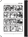
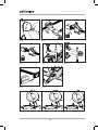
Fig. 1
Fig. 5
Fig. 8
Fig. 12
Fig. 2
Fig. 6
Fig. 10
Fig. 3
Fig. 7
Fig. 11
Fig. 4
Fig. 9

4
www.evolutionpowertools.com
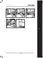
Fig. 16 Fig. 17
Fig. 15
Fig. 18
Fig. 19 Fig. 20
Fig. 21a Fig. 21b Fig. 21c
Fig. 13 Fig. 14

5
www.evolutionpowertools.com
EN
Fig. 22 Fig. 23 Fig. 24
Fig. 25 Fig. 26
12

6
www.evolutionpowertools.com
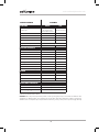
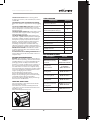
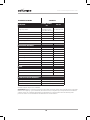
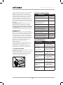
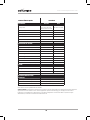
SPECIFICATIONS S355MCS
MACHINE UK/EU USA
Product code
UK 220-240V:102-0001,
UK 110V:102-0002,
EU 220-240V:102-0003
UK 120V:102-0004
Motor (UK/EU) 220V-240V ~ 50Hz 2200W -
Motor (UK) 110V ~ 50Hz 1600W -
Motor (USA) 120V ~ 60Hz - 15A
Speed (No Load) 1550 min-1 1450 min-1
Weight (With Blade) 35kg
Power Cord 3 m 10 feet
CUTTING CAPACITY
Mild Steel Plate (Max. Thickness) 12 mm 1/2 ”
Stainless Steel Plate (Max. Thickness)
5 mm ◊13/64 ” ◊
Square Tube at 90˚ 120 x 120mm 4-3/4” x 4-3/4”
Square Tube at 45˚ 100 x 100mm 3-29/32” x 3-29/32”
Rectangle Tube at 90° 100 x 165mm 3-29/32” x 6-7/16”
Rectangle Tube at 45° 100 x 110mm 3-29/32” x 4-3/8”
Round Tube at 90° Ø 120mm Ø 4-11/16”
Round Tube at 45° Ø 110mm Ø 4-5/16”
Minimum Cut Off Piece Length 8 mm 5/16 ”
BLADE
Diameter 355mm 14”
Bore 25.4mm 1”
Kerf 2.4 mm .094”
Mild Steel Blade No. Teeth 66
NOISE EMISSION DATA*
Sound Pressure Level LPA 110V: 94,9 dB(A) / 220-240V: 94,8 dB(A)
Sound Power Level LWA 110V: 107,9 dB(A) / 220-240V: 107,8 dB(A)
Uncertainty, KpA & KWA 3dB(A)
◊ Stainless Steel blade must be fitted.
WARNING: Due to the power input of this product on start up, voltage drops may occur and this can influence other
equipment (e.g. dimming lights). So for technical reasons we advise, if the mains-impedance is Zmax< 0.069Ω, these
disturbances are not expected. If you require further clarification, you may contact your local power supply authority.

7
www.evolutionpowertools.com
EN
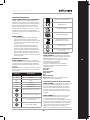
POLARIZED PLUG
WARNING (USA ONLY): To reduce the risk of
electric shock, this equipment has a polarized plug
(one blade is wider than the other). This plug will
fit in a polarized outlet only one way. If the plug
does not fit fully in the outlet, reverse the plug. If
it still does not fit, contact a qualified electrician to
install the proper outlet. Do not change the plug
in any way.
WARNING:
• that the vibration emissions during actual use
of the power tool can differ from the declared
values depending on the ways in which the
tool is used especially what kind of workpiece
is processed; and
• of the need to identify safety measures to
protect the operator that are based on an
estimation of exposure in the actual conditions
of use (taking account of all parts of the
operating cycle such as the times when the
tool is switched off and when it is running idle
in addition to the trigger time).
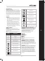
LABELS & SYMBOLS
WARNING: Do not operate this machine
if warning and/or instruction labels are missing
or damaged. Contact Evolution Power Tools for
replacement labels.
Note: All or some of the following symbols may
appear in the manual or on the product.
Symbol Description
VVolts
AAmperes
Hz Hertz
min-1 Speed
~Alternating Current
noNo Load Speed
Wear Safety Goggles
Wear Ear Protection
Wear Dust Protection
Read Instructions
Double Insulation Protection
CE Certification
UKCA Certification
TUV SUD Certification
Waste electrical and
electronic equipment
Warning
Do not touch - keep hands away
INTENDED USE OF THIS POWER TOOL
WARNING: This product has been designed to
be used with special Evolution blades. Only use
accessories designed for use in this machine
and/or those recommended specifically
by Evolution Power Tools Ltd.
When fitted with an appropriate blade
this machine can be used to cut:
Mild Steel
Thin Steel
Stainless Steel
Aluminium
Wood
Masonry
Note: Cutting galvanised steel may reduce
blade life.
PROHIBITED USE OF THIS POWER TOOL
WARNING: This product is a hand operated
mitreing chop saw and must only be used as
such. It must not be modified in any way, or
used to power any other equipment or drive any
other accessories other than those mentioned in
this Instruction manual.
WARNING: This machine is not intended for use
by persons (including children) with reduced
physical, sensory or mental capabilities, or lack
of experience and knowledge, unless they
have been given supervision or instruction
concerning the safe use of the machine by a
person responsible for their safety and who is
competent in its safe use. Children should be
supervised to ensure that they do not have
access to, and are not allowed to play with, this
machine.

8
www.evolutionpowertools.com
ELECTRICAL SAFETY
This machine is tted with the correct moulded
plug and mains lead for the designated market. If
the supply cord of this power tool is damaged, it
must be replaced by a specially prepared supply
cord available through the service organization
OUTDOOR USE
WARNING: For your protection if this tool is to be
used outdoors it should not be exposed to rain,
or used in damp locations. Do not place the tool
on damp surfaces. Use a clean, dry workbench
if available. For added protection use a residual
current device (R.C.D.) that will interrupt the
supply if the leakage current to earth exceeds
30mA for 30ms. Always check the operation of the
residual current device (R.C.D.) before using the
machine.
If an extension cable is required it must be a
suitable type for use outdoors and so labelled.
The manufacturers instructions should be
followed when using an extension cable.
GENERAL POWER TOOL
SAFETYWARNINGS
These General Power Tool Safety Instructions are
as specified in EN 62841-1: 2015 &
EN IEC 62841-3-9:2020/A11:2020
WARNING: Read all safety warnings,
instructions, illustrations and specifications
provided with this power tool. Failure to follow all
instructions listed below may result in
electric shock, fire and/or serious injury.
Save all warnings and instructions for future
reference. The term “power tool” in the warnings
refers to your mains-operated (corded) power tool
or battery-operated (cordless) power tool.
1) General Power Tool
Safety Warnings [Work area safety]
a) Keep work area clean and well lit.
Cluttered or dark areas invite accidents.
b) Do not operate power tools in explosive
atmospheres, such as in the presence of
flammable liquids, gasses or dust. Power
tools create sparks which may ignite the
dust or fumes.
c) Keep children and bystanders away while
operating power tool. Distractions can cause you
to lose control.
2) General Power Tool Safety Warnings
[Electrical Safety]
a) Power tool plugs must match the outlet.
Never modify the plug in any way. Do not use any
adapter plugs with earthed (grounded) power
tools. Unmodified plugs and matching outlets will
reduce the risk of electric shock.
b) Avoid body contact with earthed or
grounded surfaces, such as pipes, radiators,
ranges and refrigerators. There is an increased
risk of electric shock if your body
is earthed or grounded.
c) Do not expose power tools to rain or wet
conditions. Water entering a power tool will
increase the risk of electric shock.
d) Do not abuse the cord. Never use the cord
for carrying, pulling or unplugging the power
tool. Keep cord away from heat, oil, sharp edges
or moving parts. Damaged or entangled cords
increase the risk of electric shock.
e) When operating a power tool outdoors, use
an extension cord suitable for outdoor use. Use
of a cord suitable for outdoor use reduces the risk
of electric shock.
f) If operating a power tool in a damp location
is unavoidable, use a residual current device
(RCD) protected supply.
Use of an RCD reduces the risk of
electric shock.
3) General Power Tool Safety Warnings
[Personal Safety].
a) Stay alert, watch what you are doing and use
common sense when operating a power tool. Do
not use a power tool while you are tired or under the
influence of drugs, alcohol or medication. A moment of
inattention while operating power tools may result in
serious personal injury.
b) Use personal protective equipment. Always
wear eye protection. Protective equipment such
as dust masks, non-skid safety shoes, hard hat or
hearing protection used
for appropriate conditions will reduce
personal injuries.
c) Prevent unintentional starting. Ensure the
switch is in the off-position before connecting to
power source and or battery pack, picking up or
carrying the tool. Carrying power tools with your
finger on the switch or energising the power tools
that have the switch on
invites accidents.
d) Remove any adjusting key or wrench before
turning the power tool on. A wrench or key left
attached to a rotating part of
a power tool may result in personal injury.
e) Do not overreach. Keep proper footing and
balance at all times. This enables better control
of the power tool in unexpected situations.
f) Dress properly. Do not wear loose clothing
or jewellery. Keep your hair, clothing and gloves
away from moving parts. Loose clothes, jewellery
or long hair can be caught in
moving parts.
g) If devices are provided for the connection
of dust extraction and collection facilities,
ensure that these are connected and properly
used. Use of dust collection
can reduce dust-related hazards.
h) Do not let familiarity gained from frequent
use of tools allow you to become
complacent and ignore tool safety principles.
A careless action can cause severe injury within a
fraction of a second.
4) General Power Tool Safety Warnings [Power
tool use and care].
a) Do not force the power tool. Use the correct
power tool for your application. The correct power
tool will do the job better and safer at a rate for

9
www.evolutionpowertools.com
EN
which it was designed.
b) Do not use the power tool if the switch
does not turn it on or off. Any power tool
that cannot be controlled with the switch
is dangerous and must be repaired.
c) Disconnect the plug from the power source
and/or remove the battery pack, if
detachable, from the power tool before making
any adjustments, changing
accessories, or storing power tools. Such
preventive safety measures reduce the
risk of starting the power tool accidentally.
d) Store idle power tools out of the reach of
children and do not allow persons unfamiliar
with the power tool or these Instructions
to operate the power tool. Power tools are
dangerous in the hands of untrained users.
e) Maintain power tools and accessories. Check
for misalignment or binding of
moving parts, breakage of parts and any other
condition that may affect the power tool’s
operation. If damaged, have the power tool
repaired before use. Many accidents are caused by
poorly maintained power tools.
f) Keep cutting tools sharp and clean.
Properly maintained cutting tools with
sharp cutting edges are less likely to bind
and are easier to control.
g) Use the power tool, accessories and tool
bits etc. in accordance with these instructions,
taking into account the working conditions and
the work to be performed. Use of the power tool
for operations different fromthose intended
could result in a hazardous situation.
h) Keep handles and grasping surfaces dry,
clean and free from oil and grease. Slippery
handles and grasping surfaces do not allow for
safe handling and control of the
tool in unexpected situations.
5) General Power Tool Safety Warnings
[Service]
a) Have your power tool serviced by a qualified
repair person using only identical replacement
parts. This will ensure that the safety of the power
tool is maintained.
HEALTH ADVICE
WARNING: When using this machine,
dust particles may be produced. In some
instances, depending on the materials you
are working with, this dust can be particularly
harmful. If you suspect that paint on the surface
of material you wish to cut contains lead, seek
professional advice. Lead based paints should only
be removed by a professional and you should not
attempt to remove it yourself.
Once the dust has been deposited on surfaces,
hand to mouth contact can result in the ingestion
of lead. Exposure to even low levels of lead can
cause irreversible brain and nervous system
damage. The young and unborn children are
particularly vulnerable.
You are advised to consider the risks associated
with the materials you are working with and to
reduce the risk of exposure.
As some materials can produce dust that may be
hazardous to your health, we recommend the use
of an approved face mask with replaceable filters
when using this machine.
You should always:
• Work in a well-ventilated area.
• Work with approved safety equipment, such
as dust masks that are specially designed to
filter microscopic particles.
WARNING: The operation of any power tool can
result in foreign objects being thrown towards
your eyes, which could result in severe eye
damage. Before beginning power tool operation,
always wear safety goggles or safety glasses with
side shield or a full face shield where necessary.
Safety instructions for mitre saws
a) Mitre saws are intended to cut wood or
wood-like products, they cannot be used with
abrasive cut-off wheels for cutting ferrous
material such as bars, rods, studs, etc. Abrasive
dust causes moving parts such as the lower guard
to jam. Sparks from abrasive cutting will burn the
lower guard, the kerf insert and other plastic parts.
b) Use clamps to support the workpiece
whenever possible. If supporting the
workpiece by hand, you must always keep
your hand at least 100 mm from either side
of the saw blade. Do not use this saw to
cut pieces that are too small to be securely
clamped or held by hand. If your hand is
placed too close to the saw blade, there is an
increased risk of injury from blade contact. c) The
workpiece must be stationary and clamped or
held against both the fence and the table. Do
not feed the workpiece into the blade or cut
“freehand” in any way. Unrestrained or moving
workpieces could be thrown at high speeds,
causing injury.
d) Push the saw through the workpiece. Do
not pull the saw through the workpiece. To
make a cut, raise the saw head and pull it out
over the workpiece without cutting, start the
motor, press the saw head down and push the
saw through the workpiece. Cutting on the pull
stroke is likely to cause the saw blade to climb
on top of the workpiece and violently throw the
blade assembly towards the operator.
e) Never cross your hand over the intended
line of cutting either in front or behind the
saw blade. Supporting the workpiece “cross
handed” i.e. holding the workpiece to the right of
the saw blade with your left hand or vice versa is
very dangerous.
f) Do not reach behind the fence with either
hand closer than 100 mm from either side of
the saw blade, to remove wood scraps, or for
any other reason while the blade is spinning.
The proximity of the spinning saw blade to
your hand may not be obvious and you may be
seriously injured.
g) Inspect your workpiece before cutting. If
the workpiece is bowed or warped, clamp it
with the outside bowed face toward the fence.

10
www.evolutionpowertools.com
Always make certain that there is no gap
between the workpiece, fence and table along
the line of the cut. Bent or warped workpieces
can twist or shift and may cause binding on the
spinning saw blade while cutting. There should be
no nails or foreign objects in the workpiece.
h) Do not use the saw until the table is clear
of all tools, wood scraps, etc., except for the
workpiece. Small debris or loose pieces of wood
or other objects that contact the revolving blade
can be thrown with high speed.
i) Cut only one workpiece at a time. Stacked
multiple workpieces cannot be adequately
clamped or braced and may bind on the blade or
shift during cutting.
j) Ensure the mitre saw is mounted or placed
on a level, firm work surface before use. A
level and firm work surface reduces the risk of the
mitre saw becoming unstable.
k) Plan your work. Every time you change the
bevel or mitre angle setting, make sure the
adjustable fence is set correctly to support
the workpiece and will not interfere
with the blade or the guarding system.
Without turning the tool “ON” and with no
workpiece on the table, move the saw blade
through a complete simulated cut to assure there
will be no interference or danger of cutting the
fence.
l) Provide adequate support such as table
extensions, saw horses, etc. for a workpiece
that is wider or longer than the table top.
Workpieces longer or wider than the mitre
saw table can tip if not securely supported. If
the cut-off piece or workpiece tips, it can lift the
lower guard or be thrown by the spinning blade.
m) Do not use another person as a substitute
for a table extension or as additional support.
Unstable support for the workpiece can cause the
blade to bind or the workpiece to shift during the
cutting operation pulling you and the helper into
the spinning blade.
n) The cut-off piece must not be jammed or
pressed by any means against the spinning
saw blade. If confined, i.e. using length stops, the
cut-off piece could get wedged against the blade
and thrown violently.
o) Always use a clamp or a fixture designed to
properly support round material such as rods
or tubing. Rods have a tendency to roll while
being cut, causing the blade to “bite” and pull the
work with your hand into the blade.
p) Let the blade reach full speed before
contacting the workpiece. This will reduce the
risk of the workpiece being thrown.
q) If the workpiece or blade becomes jammed,
turn the mitre saw off. Wait for all moving
parts to stop and disconnect the plug from
the power source and/or remove the battery
pack. Then work to free the jammed material.
Continued sawing with a jammed workpiece
could cause loss of control or damage to the mitre
saw.
r) After finishing the cut, release the switch,
hold the saw head down and wait for the
blade to stop before removing the cut-off
piece. Reaching with your hand near the coasting
blade is dangerous.
s) Hold the handle firmly when making an
incomplete cut or when releasing the switch
before the saw head is completely in the
down position. The braking action of the saw
may cause the saw head to be suddenly pulled
downward, causing a risk of injury.
WARNING: If any parts are missing, do not
operate your machine until the missing parts are
replaced. Failure to follow this rule could result in
serious personal injury.
ADDITIONAL WARNINGS
1. Keep guards in place and in working order.
2. Remove adjusting keys and wrenches. Form
habit of checking to see that keys and adjusting
wrenches are removed from tool before turning
it on.
3. Keep work area clean. Cluttered areas and
benches invite accidents.
4. Don’t use in dangerous environment. Don’t
use power tools in damp or wet
locations, or expose them to rain. Keep
work area well lit.
5. Keep children away. All visitors should be kept
safe distance from work area.
6. Make workshop child proof with padlocks,
master switches, or by removing starter keys.
7. Don’t force the tool. It will do the job better
and safer at the rate for which it was designed.
8. Use the right tool. Don’t force the tool or
attachment to do a job for which it was
not designed.
9. Use proper extension cord. Make sure your
extension cord is in good condition. When using
an extension cord, be sure to use one heavy
enough to carry the current your product will
draw. An undersized cord will cause a drop in line
voltage resulting in loss of power and overheating.
The table on the next page shows the correct size
to use depending on cord length and nameplate
ampere rating. If in doubt, use the next heavier
gauge. The smaller the gauge number, the heavier
the cord.
10. Wear proper apparel do not wear loose
clothing, gloves, neckties, rings, bracelets, or
other jewellery which may get caught in moving
parts. Nonslip footwear is recommended. Wear
protective hair covering to contain long hair.
11. Always use safety glasses. Also use face or
dust mask if cutting operation is dusty. Everyday
eyeglasses only have impact resistant lenses, they
are not safety glasses.
12. Secure work. Use clamps or a vise to hold
work when practical. It’s safer than using your
hand and it frees both hands to operate tool.
13. Don’t overreach. Keep proper footing and
balance at all times.
14. Maintain tools with care. Keep tools
sharp and clean for best and safest performance.
Follow instructions for lubricating and changing
accessories.

11
www.evolutionpowertools.com
EN
15. Disconnect tools before servicing; when
changing accessories, such as blades, bits, cutters,
and the like.
16. Reduce the risk of unintentional stating.
Make sure switch is in off position before plugging
in.
17. Use recommended accessories. Consult the
owner’s manual for recommended accessories.
The use of improper accessories may cause risk of
injury to persons.
18. Never stand on the tool serious injury could
occur if the tool is tipped or if the cutting tool is
unintentionally contacted.
19. Check damaged parts. Before further use
of the tool, a guard or other part that is damaged
should be carefully checked to determine that it
will operate properly and perform its intended
function - check for alignment of moving parts,
binding of moving parts, breakage of parts,
mounting, and any other conditions that may
affect its operation. A guard or other part that is
damaged should be properly repaired or replaced.
20. Direction of feed. Feed work into a blade
or cutter against the direction of rotation of the
blade or cutter only.
21. Never leave tool running unattended. Turn
power off. Don’t leave the tool until it comes to a
complete stop.
GETTING STARTED UNPACKING
Caution: This packaging contains sharp objects.
Take care when unpacking. Remove the machine,
together with the accessories supplied from the
packaging. Check carefully to ensure that the
machine is in good condition and account for all
the accessories listed in this manual. Also make
sure that all the accessories are complete. If any
parts are found to be missing, the machine and its
accessories should be returned together in their
original packaging to the retailer.
Do not throw the packaging away;
keep it safe throughout the guarantee period.
Dispose of the packaging in an environmentally
responsible manner. Recycle if possible.
Do not let children play with empty plastic bags
due to the risk of suffocation.
SERIAL NO. / BATCH CODE
The serial number can be found on the motor
housing of the machine.
For instructions on how to identify the batch
code, please contact the Evolution Power Tools
helpline or go to:
www.evolutionpowertools.com
ITEMS SUPPLIED
Description Quantity
Instruction Manual 1
14” (355mm) Mild Steel TCT Blade
1
Double ended hex key
5mm/8mm (Blade Change) 1
V-Block 3
Cutting head assembly 1
Base/table assembly 1
Rail bracket and fixings 1
Thumb screws 3
Top clamp 1
Clamp cross bar 1
Front clamp 2
REPLACEMENT BLADES
Description Part No
14” (355mm)
Multi-Material Cutting
TCT Blade
(UK/EU) RAGEBLADE-
355MULTI
(USA) RAGE355BLADE
14” (355mm)
Diamond Blade
(UK/EU) RAGEBLADE-
355DIAMOND
(USA) 14BLADEDM
14” (355mm) Mild Steel
Cutting Blade
(UK/EU) M355TCT-66CS
(USA) 14BLADEST
14” (355mm) Stainless
Steel Cutting Blade
(UK/EU) S366TCT-90CS
(USA) 14BLADESS
14” (355mm) Thin Steel
Cutting Blade
(UK/EU) T355TCT-90CS
(USA) 14BLADETS
14” (355mm)
Aluminium/ Aluminum
Cutting Blade
(UK/EU) A355TCT-80CS
(USA) 14BLADEAL
14” (355mm) Wood
Cutting Blade* (USA) GW355TCT-60
*Complies with EN 847-1

12
www.evolutionpowertools.com
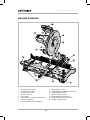
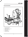
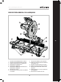
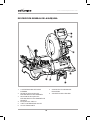
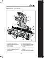
MACHINE OVERVIEW
1. LOWER BLADE GUARD
2. UPPER BLADE GUARD
3. CLAMP CROSS BAR
4. FRONT CLAMP X2
5. TOP CLAMP
6. TOP CLAMP QUICK RELEASE BUTTON
7. CUTTING HANDLE
8. CUTTING HEAD HOLD DOWN PIN
9. MITRE ANGLE SCALE
10. WORK BENCH MOUNTING HOLES X4
11. BLADE ARBOR GUARD
12. MITRE LOCKING KNOB
13. MITRE INDEX PUSH BUTTON
14. CARBON BRUSHES ACCESS CAP
15. ARBOR LOCK BUTTON
1
2
5
6
3
4
7
8
9
13
14
12
11
10
15

13
www.evolutionpowertools.com
EN
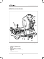
MACHINE OVERVIEW
1. DOUBLE ENDED HEX KEY
2. SLIDE LOCKING LEVER
3. SPRING LOADED SLIDE LOCK PIN
4. TRIGGER LOCK OFF
5. ON/OFF TRIGGER SWITCH
6. CARRY HANDLE
7. TOP CLAMP SOCKETS
8. REAR RAIL SUPPORT
1
5
4
2
7
3
8
6

14
www.evolutionpowertools.com
ASSEMBLY & PREPARATION
There are 6 main parts to be assembled:
• Rotary base and table assembly
• Cutting head in the up position
• Clamp cross bar assembly
• Front clamps
• Top Clamp
• Blade
Remove top foam insert, housing all clamping and
ancillary parts from the main carton.
Remove second foam insert housing the cutting
head assembly. Remove cutting head assembly
from the foam and set aside.
Remove base/table assembly from carton and
place on stable surface.
Rotate table to 0 degree mitre angle by loosening
locking knob, depressing index override button
and retightening locking knob (Fig.1)
Ensure the rear of the machine is facing towards
you, giving access to the rails (Fig.2)
NOTE: In this position the left hand rail includes
through holes which engage with the slide
controls on the cutting head.
Carefully fit the cutting head assembly onto the
rails with the motor oriented to the right.
Slide cutting head assembly fully on to the rails.
(Fig.3)
Remove and discard slide locking pin override
spacer (Fig.4)
Ensure spring loaded pin engages with the hole
closest to the rotating table for stability during
assembly.
Fit rear rail support on to the rails so the mounting
holes are visible facing up. Fasten the rail support
with 2x cap screws and washers supplied with the
on board hex key (Fig.5)
Rotate the machine around so the front of the
machine is facing you. Fit clamp cross bar by
sliding vertical posts into the sockets on the base,
ensuring the cross bar remains level (Fig.6)
Fit thumb screws in base. (Fig.7)
Whilst holding the blade guard, cut and remove
the plastic zip tie and carefully allow the blade
guard to move to it’s safe operating closed
position.
Ensure locking pin (Fig.8) is retracted before
moving the cutting head into the down position.
PERMANENTLY MOUNTING THE SAW
WARNING: Only attempt the following
procedures with the machine disconnected from
the mains power supply.
There are four mounted holes on the base through
which suitable bolts (not supplied) can be placed
to secure the machine.
Site the machine giving consideration to the
following guidelines:
• To avoid injury from flying debris, position the
saw so that other people or bystanders cannot
stand too close (or behind) it.
• Locate the saw on a firm, level surface where
there is plenty of room for handling and
properly supporting the workpiece.
• Ensure that the workbench or other supporting
structure is firm and stable and does not ‘rock’.
• Ensure that the power cord cannot become
entangled with any part of the machine during
cutting operations.
• Ensure that the power cord is routed in such a
way that it does not pose a trip (or any other
type) of hazard to the operator or
any bystanders.
TRANSPORTING THE SAW
Only transport this machine with the Cutting Head
in the locked down position (Fig. 8 & 9) and the
Locking Pin fully engaged in its socket.
Caution! This saw weighs 35kg and requires two
person lift. Use the carry handles moulded into
the machine base (See machine overview).
REMOVING OR INSTALLING A BLADE
WARNING: Only use genuine Evolution blades
designed for this machine see ‘replacement
blades’. It is recommended that the operator
considers wearing protective gloves when
handling the blade during installation or when
changing the machine’s blade.
Note: Only use saw blades that are marked with
a speed equal or higher than the speed marked
on the tool.
REMOVING A BLADE:
• Ensure that the Cutting Head is in its upper
position.
• Using the hex key supplied, loosen the front
arbor cover bolt and rotate the arbor cover out
of the way. (Fig. 10).
• Press the arbor lock button (Fig. 11) and use
the supplied hex key to remove the blade bolt.
The blade may rotate slightly until the arbor
lock engages.
• Remove the arbor bolt, washer and outer blade
flange. (Fig. 12).
• Open the blade guard and carefully remove the
old blade. Leave the inner blade flange in place
INSTALLING A BLADE:
• Install the new blade, ensuring the directional
arrow on the blade matches the direction of
the arrow on the upper blade guard (Fig. 13).

15
www.evolutionpowertools.com
EN
• Allow the blade guard to close and refit the
outer blade flange and washer.
• Partially refit the arbor bolt, press the arbor
lock button and fully tighten with the supplied
hex key.
• Return arbor cover to closed position and
retighten arbor cover bolt.
After replacing a blade, always run the machine,
without load to ensure the blade is seated
correctly.
CROSS BAR & FRONT CLAMPS, FITMENT AND
OPERATION
The cross bar is the mount for the front clamp
assemblies.
2 front clamps are supplied to allow a wide range
of safe clamping options.
When installed, the cross bar has a range of
vertical movement so that the front clamps can
be aligned in the optimum position for different
workpieces.
The vertical posts feature 6 small, and 1 large
grooves which, when installed, make audible
clicks as the bar height is adjusted throughout the
range of vertical movement.
This aids the user in ensuring the clamp bar is
kept level.
At maximum safe operating height, a final larger
groove indicates end of travel.
Thumb screws are used to secure the cross bar at
the selected height.
Fit front clamp assemblies by sliding on to the
cross bar, (Fig.14) this can be done from either the
left or the right side.
Front clamps are equipped with a long lead/acme
screws and quick release levers to aid in rapid
setting and releasing of workpieces.
(Fig.15 & 16)
OPERATE THE QUICK RELEASE MECHANISM:
• Lift and rotate quick release lever (Fig. 15)
rearwards.Slide the front jaw to the required
position.
• Return the lever to its normal service position
to tighten the clamp (Fig. 16).
• Check the security of the workpiece before
attempting to make a cut.
TOP CLAMP, FITMENT AND OPERATION
Fit the remaining T bolt to the top clamp arm.
Top clamp can be fitted at one of 5 different
positions in the rear fence depending upon the
cut.
To fit the top clamp slide the vertical post into the
chosen socket in the rear fence. (Fig.17)
The bottom section of the vertical post is knurled,
to engage in the sockets in the fence to secure the
clamp when in use.
There are 2 methods to adjust the height of the
top clamp.
1. The Acme/Lead screw has a quick release
button to allow free movement.
2. The clamp arm can be moved along the vertical
post and secured using the thumb screw. (Fig.18)
NOTE: Additional M6 tapped holes are available
on each fence socket which can be used with
older Evolution mitre saw top clamps which do
not have knurling.
V BLOCKS
V blocks are supplied with this product and should
be used where necessary on both top and front
clamps for safe cutting.
V blocks should particularly be used for safe
cutting on workpieces that are round or have
corners.
For safe and easy retention of V blocks, the clamp
feet feature spring loaded ball catches.
V blocks are fitted by sliding on to clamp feet
(Fig.19)
MITRE CUT ADJUSTMENT
The saw will allow mitre cuts to be made at any
angle between 0 and 46 degrees left and right,
there are also detents at popular angles to help
locate these including 0, 15, 22.5, 30 and 45.
To adjust the mitre angle, first turn the mitre
locking knob to loosen and depress index override
button (Fig.20) rotate the table to the required
angle, release index override button and securely
tighten the mitre locking knob for safe cutting.
NOTE: When selecting a mitre angle, prior to
cutting, ensure all clamps are fully clear of the
blade path and cutting head through its full
rotation.
WARNING:
Always use both front and top clamps when
making any cut.
Prior to making any cut, ensure all clamps are fully
clear of the blade path and cutting head through
its full rotation. Always perform a test rotation of
the cutting head without the blade spinning.

16
www.evolutionpowertools.com
ADJUSTING CUT HEAD POSITION
The rail adjustment function on this product is to
allow the user to move the blade to the optimum
position to cut several popular sizes and profiles of
metal. (Fig.27)
There are 3 indexed positions available, Front,
Centre and Rear. See (Fig.21 a,b,c)
To adjust the position of the cutting head, rotate
the locking lever (Fig.22) Retract the spring
loaded locking pin, move the cutting head on
the rails to the required position (Fig.23) Ensure
locking pin fully engages into the relevant rail
hole, tighten locking lever. (Fig.24)
WARNING: This machine is not to be used for
sliding cuts, The cutting head MUST be locked
into one of the 3 index positions during all cutting.
This product is preset and calibrated in the factory
so the blade is at 90-degrees to the rear fences.
If a user wants to calibrate their machine after
transportation / assembly > dis-assembly the
following method can be employed.
Firstly loosen the screws securing the mitre angle
plate (Fig.25) with the cutting head in the locked
down position. Check, using an engineers square
if the blade is at right angles to the fence – if not
adjust to the square position; and retighten the
screws.
After this, check the pointer is aligned with the
zero graduation mark – if not loosen its retaining
screw, reposition as necessary and retighten this.
WARNING: Only clear chippings from the
machine with the machine disconnected from the
mains power supply.
Some of the chippings may be sharp, or in other
ways pose a hazard to the operator. It may be
necessary for the operator to wear suitable PPE.
Dispose of the chippings in an environmentally
responsible way.
OPERATING ADVICE
PRE OPERATION CHECKS
Note: As all operating environments are unique
and diverse, Evolution Power Tools offers the
following general advice on safe operational
procedures and practices for consideration by the
operator.
This advice cannot be exhaustive as Evolution has
no influence on the type of workshops or working
environments in which this machine may be used.
We recommend that the operator seeks advice
from a competent authority or the workshop
supervisor if they are at unsure about any aspect
of using these machines.
It is important that routine safety checks are
carried out (at each time of usage) before the
operator uses the machine.
WARNING: These pre-use safety checks should be
carried out with the machine disconnected from
the mains power supply.
• Check that all safety guards are operating
correctly, and that all adjustment handles/
screws are securely tightened.
• Check that the blade is secure and installed
correctly. Also check that it is the correct blade
for the material being cut.
• Check the security of the workpiece in
the machine.
• Check the integrity of the power cord and its
position and routing.
PPE
The operator should wear all relevant PPE
(Personal Protection Equipment) necessary for
the task ahead. This could include safety glasses,
dust masks, safety shoes etc.
PREPARING TO MAKE A CUT
WARNING: Do not overreach. Keep good footing
and balance. Stand to one side so that your face
and body are out of line of a possible kickback.
WARNING: Freehand cutting is a major cause of
accidents and should not be attempted.
• The machines base should be clean and free
from any ‘swarf’ or sawdust etc. before the
workpiece is clamped into position.
• Ensure that the workpiece is firmly secured in
the vice.
• Ensure that the ‘cut-off’ material is free to move
sideways away from the blade when the cut is
completed.
• Ensure that the ‘cut-off’ piece cannot become
‘jammed’ in any other part of the machine.
If the workpiece being cut could cause your hand
or fingers to come within 150mm of the saw
blade, the workpiece is too small.
THE ON/OFF TRIGGER SWITCH
These models are equipped with a none latching
safety start trigger switch.
TO START THE MOTOR:
• Slide the safety lock on the left side of the
trigger switch to the left (Fig. 26).
• Depress the main trigger switch.
WARNING: Never start the saw with the cutting
edge of the saw blade in contact with the
workpiece surface.

17
www.evolutionpowertools.com
EN
MAKING A CUT
• With the Cutting Head in the upper position,
switch on the motor and allow it to reach full
operational speed.
• Gently lower the Cutting Head to the material
and use light pressure at first to prevent
the blade from grabbing. Do not ‘force’ the
machine. Let the saw blade do the work.
• Cutting performance will not improve by
applying undue pressure on the machine, and
doing so may cause blade and motor life to be
reduced.
• Reduce the pressure as the blade begins to exit
the material.
On completion of a cut release the ON/OFF trigger
switch to turn off the motor.
• Allow the Cutting Head to return to its
upper position.
• Only remove your hands, or the workpiece
from the machine, after the motor has
completely stopped and the stationary blade is
covered by the lower blade guard.
WARNING: These machines must never be used
to cut Asbestos or any material that contains, or is
suspected to contain, Asbestos.
Consult/inform the relevant authorities, and seek
additional guidance if Asbestos contamination
is suspected.
MAINTENANCE & ADJUSTMENTS
NOTE: Any maintenance must be carried out with
the machine switched off and disconnected from
the mains power supply.
• Check on a regular basis that all safety features
and guards etc are operating correctly.
• All motor bearings in this machine are
lubricated for life. No further lubrication is
required.
• Use a clean, slightly damp cloth to clean
the plastic parts of the machine. Do not use
solvents or similar products which could
damage the plastic parts.
• The machines air vents should be cleaned
using compressed dry air only.
CHECKING/REPLACING THE CARBON
BRUSHES
Excessive sparking may indicate the presence of
dirt in the motor or worn out carbon brushes.
Disconnect the machine from the power supply
before attempting to check or replace the Carbon
Brushes.
Replace both carbon brushes if either has less
than 6mm length of carbon remaining, or if the
spring or wire is damaged or burned.
TO REMOVE THE BRUSHES:
• Unscrew the plastic caps found at the back of
the motor. Be careful as the caps are spring-
loaded.
• Withdraw the brushes with their springs.
• If replacement is necessary renew the brushes
and replace the caps.
Used but serviceable brushes can be replaced,
but only as long as they are returned to the same
position, and inserted the same way round, as
they were removed from the machine.
• Run new brushes without load for
approximately 5 minutes. This will help the
bedding-in process.
ENVIRONMENTAL PROTECTION
Waste electrical products should not be disposed
of with household waste. Please recycle where
facilities exist. Check with your Local Authority or
retailer for recycling advice.

18
www.evolutionpowertools.com
EC DECLARATION OF CONFORMITY
The manufacturer of the product covered by this Declaration is:
UK: Evolution Power Tools Ltd. Venture One, Longacre Close, Holbrook Industrial Estate, Sheffield, S20 3FR.
FR: Evolution Power Tools SAS. 61 Avenue Lafontaine, 33560, Carbon-Blanc, Bordeaux, France.
The manufacturer hereby declares that the machine as detailed in this declaration fulfils all the
relevant provisions of the Machinery Directive and other appropriate directives as detailed below.
The manufacture further declares that the machine as detailed in this declaration, where
applicable, fulfils the relevant provisions of the Essential Health and Safety requirements.
The Directives covered by this Declaration are as detailed below:
2006/42/EC. Machinery Directive.
2014/30/EU. Electromagnetic Compatibility Directive.
The Restriction of the Use of certain Hazardous
Substances in Electrical Equipment (RoHS) Directive.
2002/96/EC as The Waste Electrical and Electronic Equipment (WEEE) Directive.
amended by
2003/108/EC.
And is in conformity with the applicable requirements of the following documents:
EN 62841-1:2015 • EN IEC 62841-3-9:2020/A11:2020 • EN ISO 12100:2010 •
EN IEC 55014-1:2021 • EN IEC 55014-2:2021 • EN IEC 61000-3-2:2019/A1:2021 •
EN 61000-3-3:2013 /A2:2021
Product Details
Description: S355MCS 355mm Metal cutting mitering chop saw
Evolution Model No: 102-0001, 102-0003
Brand Name: EVOLUTION
Voltage: 220 - 240V ~ 50Hz
Input: 2200W
The technical documentation required to demonstrate that the product meets the requirements
of directive has been compiled and is available for inspection by the relevant enforcement
authorities, and verifies that our technical file contains the documents listed above
and that they are the correct standards for the product as detailed above.
Name and address of technical documentation holder.
Signed: Print: Barry Bloomer - CEO
Date: 12/05/2022
UK: Evolution Power Tools Ltd. Venture One, Longacre Close, Holbrook Industrial Estate, Sheffield, S20 3FR.
FR: Evolution Power Tools SAS. 61 Avenue Lafontaine, 33560, Carbon-Blanc, Bordeaux, France.
2011/65/EU &
2015/863/EU.

19
www.evolutionpowertools.com
EN
UKCA DECLARATION OF CONFORMITY
The manufacturer of the product covered by this Declaration is:
UK: Evolution Power Tools Ltd. Venture One, Longacre Close, Holbrook Industrial Estate, Sheffield, S20 3FR.
FR: Evolution Power Tools SAS. 61 Avenue Lafontaine, 33560, Carbon-Blanc, Bordeaux, France.
The manufacturer hereby declares that the machine as detailed in this declaration fulfils all the
relevant provisions of the Machinery Directive and other appropriate directives as detailed below.
The manufacture further declares that the machine as detailed in this declaration, where
applicable, fulfils the relevant provisions of the Essential Health and Safety requirements.
The Directives covered by this Declaration are as detailed below:
This is fine for CE DoC page.Please use following for UKCA page:
UK legislation_Supply of Machinery (Safety) Regulations 2008
UK legislation_Electromagnetic Compatibility Regulations 2016
UK legislation _The Restriction of the Use of Certain Hazardous Substances in Electrical
and Electronic Equipment Regulations 2012
Noise Emission in the Environment by Equipment for use Outdoors Regulations 2001
The Waste Electrical and Electronic Equipment Regulations 2013
And is in conformity with the applicable requirements of the following documents:
BS EN 62841-1:2015 • BS EN IEC 62841-3-9:2020/A11:2020 • BS EN ISO 12100:2010 •
EN IEC 55014-1:2021 • BS EN IEC 55014-1:2021 • EN IEC 55014-2:2021 •
BS EN IEC 55014-2:2021 • EN IEC 61000-3-2:2019/A1:2021 •
BS EN IEC 61000-3-2:2019/A1:2021 • EN 61000-3-3:2013 / A2:2021 •
BS EN 61000-3-3:2013 /A2:2021
Product Details
Description: S355MCS 355mm Metal cutting mitering chop saw
Evolution Model No: 102-0001, 102-0002
Brand Name: EVOLUTION
Voltage: 110V~,50Hz: 102-0002; 220 - 240V ~, 50Hz:102-0001
Input: 1600W:102-0002; 2200W: 102-0001
The technical documentation required to demonstrate that the product meets the requirements
of directive has been compiled and is available for inspection by the relevant enforcement
authorities, and verifies that our technical file contains the documents listed above
and that they are the correct standards for the product as detailed above.
Name and address of technical documentation holder.
Signed: Print: Barry Bloomer - CEO
Date: 12/05/2022
UK: Evolution Power Tools Ltd. Venture One, Longacre Close, Holbrook Industrial Estate, Sheffield, S20 3FR.
FR: Evolution Power Tools SAS. 61 Avenue Lafontaine, 33560, Carbon-Blanc, Bordeaux, France.

20
www.evolutionpowertools.com
Notes
La page est en cours de chargement...
La page est en cours de chargement...
La page est en cours de chargement...
La page est en cours de chargement...
La page est en cours de chargement...
La page est en cours de chargement...
La page est en cours de chargement...
La page est en cours de chargement...
La page est en cours de chargement...
La page est en cours de chargement...
La page est en cours de chargement...
La page est en cours de chargement...
La page est en cours de chargement...
La page est en cours de chargement...
La page est en cours de chargement...
La page est en cours de chargement...
La page est en cours de chargement...
La page est en cours de chargement...
La page est en cours de chargement...
La page est en cours de chargement...
La page est en cours de chargement...
La page est en cours de chargement...
La page est en cours de chargement...
La page est en cours de chargement...
La page est en cours de chargement...
La page est en cours de chargement...
La page est en cours de chargement...
La page est en cours de chargement...
La page est en cours de chargement...
La page est en cours de chargement...
La page est en cours de chargement...
La page est en cours de chargement...
La page est en cours de chargement...
La page est en cours de chargement...
La page est en cours de chargement...
La page est en cours de chargement...
La page est en cours de chargement...
La page est en cours de chargement...
La page est en cours de chargement...
La page est en cours de chargement...
La page est en cours de chargement...
La page est en cours de chargement...
La page est en cours de chargement...
La page est en cours de chargement...
-
 1
1
-
 2
2
-
 3
3
-
 4
4
-
 5
5
-
 6
6
-
 7
7
-
 8
8
-
 9
9
-
 10
10
-
 11
11
-
 12
12
-
 13
13
-
 14
14
-
 15
15
-
 16
16
-
 17
17
-
 18
18
-
 19
19
-
 20
20
-
 21
21
-
 22
22
-
 23
23
-
 24
24
-
 25
25
-
 26
26
-
 27
27
-
 28
28
-
 29
29
-
 30
30
-
 31
31
-
 32
32
-
 33
33
-
 34
34
-
 35
35
-
 36
36
-
 37
37
-
 38
38
-
 39
39
-
 40
40
-
 41
41
-
 42
42
-
 43
43
-
 44
44
-
 45
45
-
 46
46
-
 47
47
-
 48
48
-
 49
49
-
 50
50
-
 51
51
-
 52
52
-
 53
53
-
 54
54
-
 55
55
-
 56
56
-
 57
57
-
 58
58
-
 59
59
-
 60
60
-
 61
61
-
 62
62
-
 63
63
-
 64
64


Evolution S355MCS Manuel utilisateur
- Catégorie
- Outils électroportatifs
- Taper
- Manuel utilisateur
dans d''autres langues
- English: Evolution S355MCS User manual
- español: Evolution S355MCS Manual de usuario
Documents connexes
-
Evolution rage3dbms1 Mode d'emploi
-
-
-
-
-
-
-
-