Garland Heavy Duty Gas Griddle Owner Instruction Manual
- Taper
- Owner Instruction Manual

Users are cautioned that maintenance and repairs must be performed by a Garland authorized service agent
using genuine Garland replacement parts. Garland will have no obligation with respect to any product that has been
improperly installed, adjusted, operated or not maintained in accordance with national and local codes or installation
instructions provided with the product, or any product that has its serial number defaced, obliterated or removed,
or which has been modified or repaired using unauthorized parts or by unauthorized service agents.
For a list of authorized service agents, please refer to the Garland web site at http://www.garland-group.com.
The information contained herein, (including design and parts specifications), may be superseded and is subject
to change without notice.
GARLAND COMMERCIAL RANGES, LTD.
1177 Kamato Road, Mississauga, Ontario L4W 1X4
CANADA
Phone: 905-624-0260
Fax: 905-624-5669
General Inquiries 1-905-624-0260
USA Sales, Parts and Service 1-800-424-2411
Canadian Sales 1-888-442-7526
Canada or USA Parts/Service 1-800-427-6668
Part # 4530868 (04/25/12) © 2012 Garland Commercial Ranges Ltd..
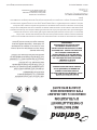
FOR YOUR SAFETY:
DO NOT STORE OR USE GASOLINE
OR OTHER FLAMMABLE VAPORS OR
LIQUIDS IN THE VICINITY OF
THIS OR ANY OTHER
APPLIANCE
WARNING:
IMPROPER INSTALLATION, ADJUSTMENT,
ALTERATION, SERVICE OR MAINTENANCE
CAN CAUSE PROPERTY DAMAGE, INJURY,
OR DEATH. READ THE INSTALLATION,
OPERATING AND MAINTENANCE
INSTRUCTIONS THOROUGHLY
BEFORE INSTALLING OR
SERVICING THIS EQUIPMENT
PLEASE READ ALL SECTIONS OF THIS MANUAL
AND RETAIN FOR FUTURE REFERENCE.
THIS PRODUCT HAS BEEN CERTIFIED AS
COMMERCIAL COOKING EQUIPMENT AND
MUST BE INSTALLED BY PROFESSIONAL
PERSONNEL AS SPECIFIED.
IN THE COMMONWEALTH OF MASSACHUSETTS
THIS PRODUCT MUST BE INSTALLED BY A
LICENSED PLUMBER OR GAS FITTER.
For Your Safety:
In a clear and observable location, post
instructions to be followed if a user smells
gas. This information shall be obtained by
consulting your local gas supplier.
INSTALLATION AND
OPERATION MANUAL
HEEGM XX CL
HIGH EFFICIENCY
RADIANT CHAR-BROILER
Français . . . . . . . . . . . . . . . . . . . . . . . . . . . . . . . . . . . . . . . . . . . . . . . . . . . . . . . . . . . . . . . . . . . . . . . . . . . . . . . . . . . . . . . . . . . . . . . . . . . . . Page 17
HEGM36CL
HEGM48CL

Part # 4530868 (04/25/12)Page 2
IMPORTANT INFORMATION
WARNING:
This product contains chemicals known to the state of California to cause cancer and/or birth defects
or other reproductive harm. Installation and servicing of this product could expose you to airborne
particles of glass wool/ceramic fibers. Inhalation of airborne particles of glass wool/ceramic fibers
is known to the state of California to cause cancer. Operation of this product could expose you to
carbon monoxide if not adjusted properly. Inhalation of carbon monoxide is known to the state of
California to cause birth defects or other reproductive harm.
Keep appliance area free and clear of combustibles.

Part # 4530868 (04/25/12) Page 3
TABLE OF CONTENTS
IMPORTANT INFORMATION. . . . . . . . . . . . . . . . . . . . . . . . . . . . . . . . . . . . . . . . . . 2
DIMENSIONS AND SPECIFICATIONS . . . . . . . . . . . . . . . . . . . . . . . . . . . . . . . . . . 4
PRE INSTALLATION . . . . . . . . . . . . . . . . . . . . . . . . . . . . . . . . . . . . . . . . . . . . . . . . . . 6
Introduction . . . . . . . . . . . . . . . . . . . . . . . . . . . . . . . . . . . . . . . . . . . . . . . . . . . . . . . . . . . . . . . . . . . . .6
Damage check . . . . . . . . . . . . . . . . . . . . . . . . . . . . . . . . . . . . . . . . . . . . . . . . . . . . . . . . . . . . . . . . . . .6
Rating Plate . . . . . . . . . . . . . . . . . . . . . . . . . . . . . . . . . . . . . . . . . . . . . . . . . . . . . . . . . . . . . . . . . . . . . .5
INSTALLATION . . . . . . . . . . . . . . . . . . . . . . . . . . . . . . . . . . . . . . . . . . . . . . . . . . . . . . 6
General . . . . . . . . . . . . . . . . . . . . . . . . . . . . . . . . . . . . . . . . . . . . . . . . . . . . . . . . . . . . . . . . . . . . . . . . . .6
Positioning and Setup . . . . . . . . . . . . . . . . . . . . . . . . . . . . . . . . . . . . . . . . . . . . . . . . . . . . . . . . . . . .6
Optional Stand . . . . . . . . . . . . . . . . . . . . . . . . . . . . . . . . . . . . . . . . . . . . . . . . . . . . . . . . . . . . . . . . . .7
Air Supply and Ventilation . . . . . . . . . . . . . . . . . . . . . . . . . . . . . . . . . . . . . . . . . . . . . . . . . . . . . . . .7
Electrical Connection . . . . . . . . . . . . . . . . . . . . . . . . . . . . . . . . . . . . . . . . . . . . . . . . . . . . . . . . . . . .7
Gas Connection . . . . . . . . . . . . . . . . . . . . . . . . . . . . . . . . . . . . . . . . . . . . . . . . . . . . . . . . . . . . . . . . . .8
Start Up . . . . . . . . . . . . . . . . . . . . . . . . . . . . . . . . . . . . . . . . . . . . . . . . . . . . . . . . . . . . . . . . . . . . . . . . .8
USE AND CARE. . . . . . . . . . . . . . . . . . . . . . . . . . . . . . . . . . . . . . . . . . . . . . . . . . . . . . 9
Operation . . . . . . . . . . . . . . . . . . . . . . . . . . . . . . . . . . . . . . . . . . . . . . . . . . . . . . . . . . . . . . . . . . . . . . .9
Warnings . . . . . . . . . . . . . . . . . . . . . . . . . . . . . . . . . . . . . . . . . . . . . . . . . . . . . . . . . . . . . . . . . . . . . . . 11
Optional Equipment . . . . . . . . . . . . . . . . . . . . . . . . . . . . . . . . . . . . . . . . . . . . . . . . . . . . . . . . . . . .11
CLEANING AND MAINTENANCE . . . . . . . . . . . . . . . . . . . . . . . . . . . . . . . . . . . . . 12
General . . . . . . . . . . . . . . . . . . . . . . . . . . . . . . . . . . . . . . . . . . . . . . . . . . . . . . . . . . . . . . . . . . . . . . . . .12
Warnings . . . . . . . . . . . . . . . . . . . . . . . . . . . . . . . . . . . . . . . . . . . . . . . . . . . . . . . . . . . . . . . . . . . . . . .12
Cleaning During Operations . . . . . . . . . . . . . . . . . . . . . . . . . . . . . . . . . . . . . . . . . . . . . . . . . . . . .13
Daily Cleaning . . . . . . . . . . . . . . . . . . . . . . . . . . . . . . . . . . . . . . . . . . . . . . . . . . . . . . . . . . . . . . . . . .13
Weekly/Periodic Cleaning . . . . . . . . . . . . . . . . . . . . . . . . . . . . . . . . . . . . . . . . . . . . . . . . . . . . . . .13
Maintenance . . . . . . . . . . . . . . . . . . . . . . . . . . . . . . . . . . . . . . . . . . . . . . . . . . . . . . . . . . . . . . . . . . .14
Service and Parts . . . . . . . . . . . . . . . . . . . . . . . . . . . . . . . . . . . . . . . . . . . . . . . . . . . . . . . . . . . . . . .14

Part # 4530868 (04/25/12)Page 4
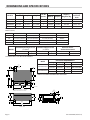
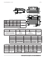
DIMENSIONS AND SPECIFICATIONS
STANDARD GRATE AVAILABLE IN ONE-SIDED OR TWO-SIDED STYLES
17-7/16in
451mm
OVERALL
HEIGHT
4.-11/16in
119mm
LEG WIDTH
TYP
LEG PITCH
"D"
14-13/16in
376mm
COOK HEIGHT
OVERALL
WIDTH
"E"
HEEGM48CL SHOWN
2-3/4in
68mm
3/4" NPT
GAS INLET
COOK WIDTH
"C"
3-7/8in
97mm
ELECTRICAL
23-7/16in
596mm
COOK DEPTH
3-5/8in
93mm
TROUGH
DEPTH
38-13/16in
986mm
OVERALL
DEPTH
8-13/16in
224mm
RAIL DEPTH
3-1/2in
89mm
1-1/8in
30mm
4.-3/4in
121mm
STANDARD
GRATE WIDTH**
RAIL FITS 1/3 PANS
**OPTIONAL FAJITA RACK REQUIRES THE REMOVAL OF 2 STANDARD GRATES
1-11/16in
43mm
ELECTRICAL
2-1/2in
63mm
3/4" NPT
GAS INLET
1-1/8in
28mm
28-15/16in
735mm
LEG DEPTH
7-7/8in
199mm
VALVE HEIGHT
10.4°
2ND GRATE
POSITION
2.2°
STANDARD
GRATE POSITION
Model #
Shipping Dimensions: In. (mm)
No. Of
Burners
Total BTU*
Shipping
Weight Lbs/Kg
Shipping
Size CuFT/
Cu/m
Width Depth Height
Natural Propane
HEEGM24CL 45/1143 45/1143 25-1/2/648 4 58,000 52,000 280/127 29.9/0.846
HEEGM36CL 45/1143 45/1143 25-1/2/648 6 87,000 78,000 420/191 29.9/0.846
HEEGM48CL 65/1651 45/1143 25-1/2/648 9 130,500 117,000 254/560 43.2/1.223
HEEGM60CL 65/1651 45/1143 25-1/2/648 11 159,500 143,000 700/318 43.2/1.223
TOTAL BTU BASED ON MANIFOLD OPERATING PRESSURE SPECIFIED IN TABLE BELOW AND APPLY TO INSTALLATIONS UP TO
2000 FT (610m).
Model COOK WIDTH "C" LEG PITCH "D" OVERALL WIDTH "E" GREASE TRAY
24" 19-7/8in (506mm) 14-1/4in (362mm) 23-1/2in (597mm) SINGLE
36" 29-7/8in (760mm) 24-1/4in (616mm) 33-1/2in (851mm) SINGLE
48" 43-7/8in (1115mm) 36-1/4in (972mm) 47-1/2in (1207mm) DUAL
60" 53-7/8in (1369mm 48-1/4in (1222mm) 57-1/2in (1461mm) DUAL
Models
Manifold Operating Pressure
w.c.(Mbar)
Manifold Supply Pressure
w.c.(Mbar)
Clearance to non-
combustible material
Natural Gas Propane Natural Gas Propane Rear (in/mm) Sides (in/mm)
All Models 4.5(11.2) 10.0(25.0) 7.0(17.4) 11.0(27.5) 0/0 0/0
*GAS INLET PIPE IS 3/4" NPT ON ALL MODELS
Model
ELECTRICAL REQUIREMENTS
Voltage Frequency Current Cord
HEEGM24&36CL
120 50-60 Hz 0.10 A NEMA 5-15P
220-240 50-60 Hz 0.05 A NOT SUPPLIED
HEEGM48&60CL
120 50-60 Hz 0.22 A NEMA 5-15P
220-240 50-60 Hz 0.11 A NOT SUPPLIED
*WIRING DIAGRAMS PROVIDED WITH EACH UNIT

Part # 4530868 (04/25/12) Page 5
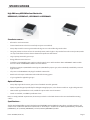
High Eciency HEEGM Radiant Charbroiler
HEEGM24CL, HEEGM36CL, HEEGM48CL & HEEGM60CL
Standard Features :
• All stainless steel construction.
• Front rail with cut outs to hold 1/3 size food pans (pans not included).
• Heavy duty reversible cast iron grates with wide edge on one side and ne edge on the other.
• Two grate positions to choose from: the standard position, with a slight 2° slope to the front or the second position, with a
10° slope to the front and more distance between the product and the burner.
• Large capacity, removable grease trays.
• Energy ecient cast iron burners.
• Complete system ON/OFF power switch(es), which ignites burners and shuts them down. HEEGM24CL & 36CL models
have one switch and HEEGM48CL & 60CL have two switches.
• Each burner outputs 14,500 BTU for natural gas & 13,000 BTU for propane gas, and is individually controlled by a manual
high-low valve.
• 9 ft power cord with NEMA 5-15P plug for standard 120V models.
• Wire brush and scraper combination tool included for cleaning grates.
• ¾” gas regulator for applicable gas type.
Optional Features :
• Heavy duty single sided cast iron grate, in lieu of standard reversible grate N/C.
• Fajita pan grate designed specically for holding/warming fajita pans, in lieu of two reversible or single sided grates N/C.
• 240V models supplied without a cord, available for export and/or non-CE countries.
• Stands are available, see HEMST specication sheet.
Note: To comply with NSF requirements, the unit may need to be sealed with silicone to the non-combustible mounting
surface.
Specications: :
Shall be Garland High Eciency (HE) Charbroiler, Model HEEGMCL with total BTU/hr rating when used with natural gas. All
stainless steel construction with front rail that holds 1/3 size food pans. Available in 24” (600mm) [HEEGM24CL], 36” (900mm)
[HEEGM36CL], 48” (1200mm) [HEEGM48CL] and 58” (1500mm) [HEEGM60CL] widths.
SPECIFICATIONS
HEGM36CL
HEGM48CL

Part # 4530868 (04/25/12)Page 6
PRE INSTALLATION
IT IS STRONGLY RECOMMENDED THAT INSTALLATION,
MAINTENANCE AND REPAIRS BE DONE BY AN AUTHORIZED
SERVICE AGENCY. FOR A LIST OF AUTHORIZED SERVICE
AGENTS, REFER TO THE GARLAND WEB SITE AT http://www.
garland-group.com
Introduction
Garland manufactures the HEEGM series broiler in several
sizes. While service and customer operation may vary
from size to size, installation is similar for each. All units are
shipped fully assembled, except for the radiants and top
grates, which are packaged in separate boxes. Each unit
is tested, adjusted and inspected at the factory prior to
shipment.
Damage Check
After unpacking the unit, be sure to carefully inspect the unit
for visible and/or concealed damage. Report any damage
immediately to your carrier to le the appropriate freight
claims.
Rating Plate
The rating plate can be found on the inside face of the left
leg. The grease drawer may need to be removed in order
to read the information. If service or replacement parts
are needed, refer to the model number (including prex &
sux letters/numbers) and serial number on the rating plate
when contacting the factory or authorized service agency.
These numbers ensure proper unit identication and aid in
providing faster and more accurate service.
The rating plate contains other important information critical
to the proper installation of the unit. It species the gas type;
gas pressure; voltage and clearance requirements for the
appliance.
INSTALLATION
THIS PRODUCT IS NOT AUTHORIZED FOR HOME OR
RESIDENTIAL USE. GARLAND WILL NOT PROVIDE SERVICE,
WARRANTY, MAINTENANCE OR SUPPORT OF ANY KIND
OTHER THAN IN COMMERCIAL APPLICATIONS.
General
In the United States, installation of this appliance must
conform to the National Fuel Gas Code ANSI Z223.1, or latest
edition, NFPA No.54-latest edition/or local code to assure
safe and ecient operation.
In Canada, installation of this appliance must comply with
CSA B149.1 and local codes.
In other countries, installation must be carried out by
a competent person, in accordance with the relevant
regulations; codes of practice and the related publications of
the country of destination.
If you have any questions regarding the installation of this
unit, contact the Garland Service Department at (800) 427-
6668 or online at http://www.garland-group.com
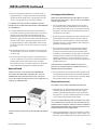
Positioning and Setup
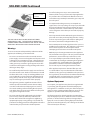
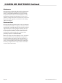
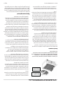
1. Carefully remove the unit from the crate base. Some
form of mechanical assistance may be required to lift and
position the broiler. With the grease drawers removed,
the unit is designed to be lifted with a pallet or lift jack as
shown in the image below.
TRAY SLIDES
FORKS
DO NOT LIFT BY GREASE DRAWER SLIDES. CARE SHOULD BE
TAKEN TO AVOID THE LEFT, RIGHT AND/OR CENTER GREASE
DRAWER SLIDES WHEN POSITIONING LIFTING EQUIPMENT.

Part # 4530868 (04/25/12) Page 7
INSTALLATION Continued
Air Supply and Ventilation
VENTILATION REQUIREMENTS MAY BE SUBJECT TO LOCAL
BUILDING AND FIRE CODES. CONSULT LOCAL AUTHORITIES
HAVING JURISDICTION.
1. For any commercial cooking appliance, means must
be provided to exhaust combustion waste products to
the outside of the building. This is especially important
for broilers, since they generate substantial amounts of
smoke when in operation.
2. A properly designed ventilating canopy should be used
for this appliance, which extends at least 6” (152mm)
beyond each side of the appliance (except against the
wall if the canopy is a wall installation) and is equipped
with lters and drip troughs.
3. Air movement should be checked during installation.
There must be adequate air intake into the building
to compensate for the amount of air removed by the
ventilation system. Without a proper balance, abnormal
atmospheric pressure will occur, aecting burner and
appliance performance. If air movement is a concern,
adjustments should be made to correct the problem by a
qualied technician.
HAVING DIFFICULTY OPENING DOORS THAT EXIT THE
BUILDING, IS AN INDICATION THAT THE BUILDING HAS A
PROBLEM WITH AIR MOVEMENT.
4. Do not permit fans to blow directly at the appliance and
avoid opening windows behind or beside the appliance.
This can create air cross-currents and/or excessive drafts
that interfere with the operation of the unit.
Electrical Connection
DISCONNECT THE POWER SUPPLY BEFORE SERVICING.
1. Standard units are supplied with a Nema 5-15P power
cord with appropriate strain relief. This will require a
suitable 120V 15Amp 60Hz outlet in close proximity to
the appliance. Consult a certied electrician if you have
concern about the suitability of the outlet.
DO NOT USE AN EXTENSION CORD TO CONNECT THIS UNIT
TO A POWER SUPPLY. DO NOT USE THIS APPLIANCE IF THE
POWER CORD IS DAMAGED. DO NOT ATTEMPT TO REPAIR A
DAMAGED POWER CORD. TAKE CARE NOT TO EXPOSE THE
POWER CORD TO HEAT OR SHARP EDGES.
2. Units supplied without a cord are intended for use with a
220-240V (LINE TO LINE) single phase power supply. The
appliance must be tted with an appropriate power cord
2. The unit is designed to sit ush on a counter, stand or
refrigerated base. Leveling of the unit is done through
adjustment of the stand casters, refrigerated base legs/
casters or using shims for countertop installation.
IT IS IMPERATIVE THAT THE UNIT IS PROPERLY LEVELED
DURING INSTALLATION TO ENSURE OPTIMAL PERFORMANCE
OF THE PRODUCT.
3. To comply with NSF requirements, the unit should be
sealed to the mounting surface with silicone. If possible,
apply silicone to the underside of both leg channels
and then put the unit in place on the mounting surface.
Otherwise, apply silicone to the surface rst and then put
the unit on the surface, placing the leg channels on the
pre-applied silicone. Avoid sealing lower stainless steel
panels to the surface, as these may need to be removed
for service.
4. Position the appliance in an area that is free and clear of
all combustibles. This unit is for use in non-combustible
locations only.
5. For service, this unit may need to be accessed from the
side. An adequate service clearance should be provided
in front of the unit to enable the unit to be brought
forward for access to serviceable components. Keep this
in mind when determining the installation location.
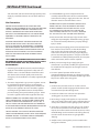
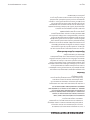
Optional Stand
STANDS SPECIFICALLY DESIGNED TO ACCOMMODATE
THESE UNITS ARE AVAILABLE FOR PURCHASE. USE THE
APPROPRIATE STAND FOR THE SIZE OF UNIT. FOR YOUR
SAFETY, BE SURE TO SECURE THE UNIT TO THE STAND WITH 4
SCREWS, AS SHOWN BELOW.
DRIVE SCREWS UP
THROUGH STAND AND
INTO UNIT LEG CHANNELS
(ONE PER CORNER)
STAND ASSEMBLY INSTRUCTIONS ARE PROVIDED WITH EACH
STAND.

Part # 4530868 (04/25/12)Page 8
INSTALLATION Continued
and strain relief, and connected to the appropriate power
supply by a certied electrician in accordance with local
codes.
Gas Connection
ENSURE THE GAS METER AND GAS PIPING ARE SIZED
CORRECTLY FOR THE AMOUNT OF GAS FLOW AND PRESSURE
THAT WILL BE NEEDED TO RUN ALL APPLIANCES IN THE
KITCHEN. UNDERSIZED GAS PIPING INTO THE KITCHEN
MAY AFFECT THE PERFORMANCE OF THIS AND/OR OTHER
EQUIPMENT. IF IN DOUBT, CONSULT YOUR LOCAL GAS
AUTHORITY.
A MANUAL OR AUTOMATIC ISOLATION VALVE MUST BE
INSTALLED ON THE GAS SUPPLY TO THE KITCHEN FOR
ACCESS IN THE EVENT OF AN EMERGENCY. THE MANUAL
VALVE OR AUTOMATIC VALVE ACCESS POINT SHOULD BE
READILY ACCESSIBLE AND LOCATED EITHER OUTSIDE THE
KITCHEN OR CLOSE TO AN EXIT. POST THE FOLLOWING
NOTICE AT THE MANUAL VALVE OR AUTOMATIC VALVE
ACCESS POINT:
“ALL DOWNSTREAM BURNER AND PILOT VALVES MUST
BE TURNED OFF PRIOR TO RESTORING THE GAS SUPPLY.
AFTER AN EXTENDED SHUT OFF, PURGE BEFORE
RESTORING GAS.”
1. A manual gas shut-o valve must be installed in the gas
supply line ahead of the appliance for safety and ease
of future service. The shut-o valve should be located
such that it can be reached quickly in the event of an
emergency. The shut-o valve is normally supplied by the
installer.
2. This unit is shipped with a gas pressure regulator. It must
be installed at the appliance prior to connecting the
equipment to the gas line. Each appliance must have its
own pressure regulator. Be sure to install the regulator
according to the gas ow direction and verify that the
pressure marking corresponds with the gas type. Failure
to install a regulator will void the equipment warranty.
PRIOR TO CONNECTING THE REGULATOR, CHECK THE GAS
SUPPLY LINE PRESSURE. THE REGULATOR SUPPLIED WITH
THE UNIT IS RATED FOR A MAXIMUM OF ½ PSI (14” WC). IF
THE GAS SUPPLY LINE PRESSURE EXCEEDS THIS MAXIMUM,
A STEP DOWN REGULATOR WILL BE REQUIRED AND MUST BE
INSTALLED IN ACCORDANCE WITH LOCAL CODES.
THE RED AIR-VENT CAP IS PART OF THE REGULATOR AND
SHOULD NOT BE REMOVED, UNLESS LOCAL CODES REQUIRE
EXTERNAL VENTING. IF EXTERNAL VENTING IS REQUIRED,
INSTALL IN ACCORDANCE WITH LOCAL CODES.
3. A certied exible gas hose and quick disconnect
assembly with suitable strain relief is recommended for
connection from the gas supply line to the unit. This will
allow the unit to be moved for future service.
FLEXIBLE HOSES & QUICK DISCONNECT DEVICES MUST
COMPLY WITH ALL LOCAL AUTHORITIES AND CODES.
IN NORTH AMERICA THIS INCLUDES ANSI Z21.69/CSA
6.16, ADDENDA Z21.69B-2006/CSA 6.16B-2006 (OR
LATEST EDITION) AND ANSI Z21.41/CSA 6.9, ADDENDA
Z21.41A-2005/CSA 6.16A-2005 (OR LATEST EDITION).
4. Only connect this unit to the type of gas shown on the
rating plate. Operating this unit with the wrong gas type
can result in abnormal performance, property damage,
injury or death.
5. Ensure that any new piping, joints and connections have
been made in a clean manner, so that dirt, threading
chips and/or other foreign matter will not clog pilots,
valves and/or controls. If necessary, purge new piping
prior to connecting the appliance. Use pipe sealant that
is certied for use with liqueed petroleum, for new joints
and/or connections, where sealant is required.
6. When pressure testing the gas supply piping to a
maximum of ½ psi (14” WC, 3.45 KPa), the appliance must
be isolated from the supply line by closing the manual
shut-o valve.
7. To ensure optimal operation of this unit, it is
recommended that the dynamic gas supply pressure into
the appliance regulator is a minimum of 1” WC higher than
the pressure stated on the rating plate.
Start Up
1. Inside the unit, ensure the burners are in the correct
position and the shields hanging under the burners have
not rotated out of position during transit.
2. Install cast radiants over each burner and place the
cooking grates in position on the unit.
3. Ensure the gas supply to the appliance is open and the
unit is connected to the power supply. Activating the one
or two power switches on the right leg operates the unit.
4. Check all gas connections for leaks using a soap solution.
Do not use an open ame to check for leaks. Be sure to
inspect connections outside and inside the unit (ie: valves,
manifold ttings and connections in the left leg channel)
to make certain all connections are gas tight after
shipping.
5. Verify the unit is running at the pressure stated on the
rating plate as follows:

Part # 4530868 (04/25/12) Page 9
INSTALLATION Continued
FOR HEEGM24 & 36 SIZE UNITS
• Connect a manometer to the test spigot on the
manifold.
• Turn on the unit and adjust the burners so that they are
all set to high.
• If necessary, adjust the pressure so that the reading
on the manometer matches the pressure value stated
on the rating plate. To adjust the pressure, access and
rotate the pressure adjustment screw on the regulator
installed at the appliance.
FOR HEEGM48 & 60 SIZE UNITS
• Connect a manometer to the test spigot on the LEFT
manifold.
• Turn on the LEFT side of the unit only (by activating the
left switch) and adjust the burners so that they are all
set to high.
• If necessary, adjust the pressure so that the reading
on the manometer matches the pressure value stated
on the rating plate. To adjust the pressure, access and
rotate the pressure adjustment screw on the regulator
installed at the appliance.
6. Inspect the ame of each burner to determine whether
adjustments to the burner air shutter are necessary.
Adjustments are made by loosening the air shutter screw;
rotating the shutter and re-tightening the screw. If the
tips of the ame appear too yellow, the shutter should be
turned to allow MORE air to enter the burner cavity. If the
ames appear to be lifting o the burner ports, the shutter
should be turned to allow LESS air to enter the burner
cavity.
Operation
IF FOR ANY REASON YOU SMELL GAS, BEFORE, DURING OR
AFTER OPERATION, TURN THE POWER OFF AND CLOSE THE
MANUAL SHUT-OFF VALVE TO THE APPLIANCE. CONTACT
AN AUTHORIZED SERVICE AGENT FOR SERVICE BEFORE
ATTEMPTING TO RESTORE GAS SUPPLY. FOR A LIST OF
AUTHORIZED SERVICE AGENTS, REFER TO THE GARLAND WEB
SITE AT http://www.garland-group.com
1. To turn on and use this appliance, the operator simply
needs to turn on the power switch(es).
FOR STANDARD 120 VOLT UNITS:
2. Models HEEGM-24CL and HEEGM-36CL have one power
switch on the lower right side of the unit. Once pushed
to the “ON” position, gas is supplied to all the burners. At
the same time a spark is supplied to each burner to ignite
the gas. Sparking will continue until a ame has been
established at all burners.
USE AND CARE
3. Models HEEGM-48CL and HEEGM-60CL have two power
switches on the lower right side of the unit. Once pushed
to the “ON” position, they operate in the same manner as
the single switch above, except they allow the operator to
run the left and right side of the broiler independently as
shown below:
• HEEGM-48CL: The left switch operates burners 1 to 4
on the left side of the unit. The right switch operates
burners 5 to 9 on the right side of the unit. The entire
unit runs when both switches are used.
• HEEGM-60CL: The left switch operates burners 1 to 6
on the left side of the unit. The right switch operates
burners 7 to 11 on the right side of the unit. The entire
unit runs when both switches are used.
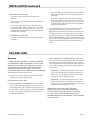
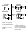
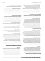
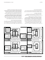
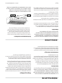
FOR OPTIONAL 220-240 VOLT UNITS, THE MAIN
POWER SWITCH NEEDS TO BE TURNED ON BEFORE
THE FUNCTIONALITY OF THE SWITCHES DESCRIBED IN
2 & 3 APPLY. REFER TO IMAGES BELOW FOR A VISUAL
COMPARISON BETWEEN THE STANDARD 120 AND OPTIONAL
220-240V MODELS.

Part # 4530868 (04/25/12)Page 10
4. Once the desired power switch(es) have been turned to
the “ON” position, the burners should ignite quickly. If
sparking continues and/or a burner does not light, shut
down power to the unit by turning the switch(es) to
the “OFF” position and wait 5 minutes before repeating
ignition. If ignition fails repeatedly, shut down power to
the unit and contact a qualied service technician.
5. It is recommended that the unit run for approximately 30
minutes on start up to reach the desired temperature.
6. For temperature adjustment, each burner has a control
knob which will adjust the height of the ame from a high
to a low position.
120V SINGLE SWITCH
120V DOUBLE SWITCH
220-240V SINGLE SWITCH
220-240V DOUBLE SWITCH
$
BURNERS
ON/OFF
LEFT SIDE
BURNERS
ON/OFF
RIGHT SIDE
BURNERS
ON/OFF
MAIN
POWER
ON/OFF
BURNERS
ON/OFF
MAIN
POWER
ON/OFF
RIGHT SIDE
BURNERS
ON/OFF
LEFT SIDE
BURNERS
ON/OFF
USE AND CARE Continued
7. To shut o the unit, the operator simply needs to turn o
the power switch(es). When shutting down for longer
periods of time, it is best to also close the manual shut-o
valve to the unit.
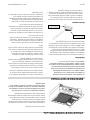
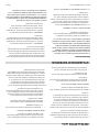
8. The cooking grates can be installed in 2 positions, to
provide exibility when preparing dierent types of food.
To install the cooking grates in the standard position,
the rear feet on the grates should be placed through the
square cutouts on the rear wall of the broiler. To install the
cooking grates in the elevated position, the groove in the
feet of the grates should be placed on the top edge of the
rear wall of the broiler. Grates must be manually moved
from one position to another; and therefore, should be
moved when the grates are cool.

Part # 4530868 (04/25/12) Page 11
THE SIDE SHIELDS MUST ALWAYS BE IN PLACE WHEN
OPERATING THIS UNIT. THE SIDE SHIELDS PREVENT THE
COOKING GRATES FROM SLIDING OFF THE SIDE OF THE UNIT,
WHEN THEY ARE PLACED IN THE ELEVATED POSITION.
Warnings
To ensure consistent and dependable performance of this
appliance, the following are recommended:
• Do not use an extension cord to connect this unit to a
power supply. Do not use this appliance if the power cord
is damaged. Do not attempt to repair a damaged power
cord. Take care not to expose the power cord to heat (ie:
under grease tray, near ue or grate support etc) and be
careful not to damage the cord by pinching under unit or
rubbing on sharp edges.
• Do not lift unit by the front rail or apply excessive force to
the rail to move the unit. Under no circumstances should
the front rail be used as a step or standing platform (ie: to
access light bulbs or grease bucket in ventilation hood).
Doing so may result in serious injury and/or death; and
may cause damage to your broiler and/or property.
• This appliance generates signicant amounts of heat
and the operator should take caution when touching
accessible surfaces that are likely to get hot. Surfaces
close to the cooking surface including the side panels,
side shields, front rail, grease tray handle and valve panel
may get hot enough to burn skin.
• Do not operate the broiler without the side shields in
place as it may adversely aect the performance of
the unit and/or allow heat to migrate to neighboring
equipment/property causing damage. The shields also
prevent the cooking grates from sliding o the side of the
unit when they are placed in the elevated position.
• Use of foil in the grease tray is not recommended.
However, if foil is being used, it must be kept tight to the
tray so that it does not obstruct the ow of air into and
around the unit, particularly between the grease tray and
the valve panel.
• It is important that the grease trays are emptied on a
regular basis. Flare ups in the grease tray are possible with
this type of appliance and excessive amounts of grease
in the tray can lead to a sustained are up or re, which
can be dangerous and result in personal and/or property
damage.
• Do not operate the broiler without the grease drawers in
place and ensure they are always fully pushed in. Failing
to do so may result in grease and/or debris spilling onto
the counter, stand and/or refrigerated base top.
• Do not attempt to service this appliance unless you are a
qualied service technician. This appliance is connected
to live electrical power. Disconnect power before
attempting to clean/remove accessible metal panels.
• Without proper cleaning & maintenance, this appliance
will accumulate oil and grease. This may result in reduced
performance, excessive are ups and/or re. It is the
user’s responsibility to prevent the hazards of grease
accumulation by cleaning & maintaining their appliance
on a regular basis. Garland will not be responsible for
performance reductions and/or res resulting from
misuse and/or poor cleaning & maintenance habits.
• If this appliance experiences abnormal are ups and/
or sustained re in any area other than the combustion
chamber (ie: the grease tray, behind the valve panel or in
the leg channel), the unit must be shut down immediately
and should not be used until it has been serviced by a
qualied technician and deemed safe to operate.
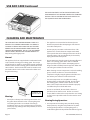
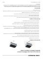
Optional Equipment
As an option, your appliance may have been supplied with
a special top grate designed to hold and heat fajita pans.
This appliance is certied to use only one of these fajita pan
grates at a time. Installing multiple fajita pan grates on one
appliance is prohibited and could void your warranty.
The fajita pan grate has been designed to accommodate
only one fajita pan per slot, in either the vertical or horizontal
position, as shown in the image below. Placing multiple
fajita pans in one slot and/or placing fajita pans at on this
grate or the standard grate may cause damage to the broiler
and could void your warranty.
USE AND CARE Continued
FOR STANDARD GRATE
POSITION, GRATE FEET SIT
IN CUTOUTS OF REAR WALL
FOR 2nd GRATE POSITION,
GRATE FEET SIT ON EDGE
OF REAR WALL

Part # 4530868 (04/25/12)Page 12
THIS APPLIANCE WILL PERFORM OPTIMALLY AND LAST
LONGER IF IT IS PROPERLY MAINTAINED. FOLLOWING A
CLEANING SCHEDULE AND HAVING THE UNIT CHECKED
PERIODICALLY BY AN AUTHORIZED SERVICE AGENT ARE
STRONGLY RECOMMENDED. FOR A LIST OF AUTHORIZED
SERVICE AGENTS, REFER TO THE GARLAND WEB SITE AT
http://www.garland-group.com
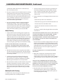
General
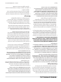
This appliance has been supplied with a combination brush/
scraper tool for cleaning your cooking grates. The scraper
side of the tool has stainless steel teeth, designed specically
to t the contours of the cooking grate and will clean hard to
remove debris. The brush side of the tool has stainless steel
wire bristles which can be used to remove ner debris and
for general cleaning.
• This appliance is connected to live electrical power.
Disconnect power before attempting to clean/remove
accessible metal panels.
• Do not spray or pour water on the unit to clean. This
appliance has several electronic components behind
access panels that can be damaged or become unsafe if
exposed to water. This unit should only be cleaned by
wiping down with a damp cloth.
• Do not attempt to clean the grates by burning o grease/
debris. The cooking grates on this unit are shielded
from open ame by the radiants. Attempting to burn
o grease/debris will likely have the opposite eect and
cause the grease/debris to stick even more.
• When cleaning cast iron components such as the cooking
grates; radiants; and burners, do not handle these
components roughly. Dropping them on the oor or in
the sink may cause them to crack and/or break.
• Cast iron components are susceptible to cracking/
breaking if they are thermally shocked. Do not expose
hot cooking grates, radiants; and/or burners to cold
water. These components must be allowed to properly
cool before they are washed with water.
• Do not use steel wool, abrasive cloths, cleaners or
powders to clean stainless steel. Do not use a metal
scraper, knife or other tool to scrape stainless steel. Doing
so may cause irreparable scratches on the stainless steel
material.
Cleaning During Operations
1. It is important to clean the grates periodically during
daily operations, using the tool provided or any other
cleaning tool of preference. Cleaning the grates as
needed throughout the day will limit the eects of grease
CLEANING AND MAINTENANCE
THE FAJITA PAN GRATE IS INSTALLED ON THE UNIT IN THE
SAME MANNER AS THE STANDARD GRATE IN THE STANDARD
POSTION. FEET ON THE REAR OF THE FAJITA GRATE SIT IN
THE SQUARE CUTOUTS ON THE REAR WALL.
USE AND CARE Continued
Warnings
• Never place a sheet pan or other large obstruction over
the grates when the broiler is hot. Covering the grates
and running the broiler as a method of cleaning is
prohibited. Doing so, may cause damage to your broiler
and/or property; endanger the safety of others; and void
your warranty.
BRUSH SIDE - FOR
GENERAL CLEANING
SCRAPER SIDE - FITS
CONTOURS OF GRATES

Part # 4530868 (04/25/12) Page 13
accumulation, which include excess smoke; are ups;
res and sub-par product.
2. The grease trough and chute should be kept clean during
daily operations to prevent grease from accumulating
near the cook surface. If necessary, stagnant grease and/
or food particles should be directed to the grease chute
using a standard 3” wide turner. If necessary, this turner
can also be used to push items/grease in the grease
chute down into the grease drawer.
3. The grease drawer(s) should be emptied periodically
during daily operations. Every environment diers,
so the frequency of this action will vary depending on
amount and type of product being cooked. Keeping the
amount of grease in the drawer to a minimum greatly
reduces the chance of are ups and sustained re.
Daily Cleaning
1. Scrape and/or brush the cooking grates using the tool
provided or any other cleaning tool of preference while
the grates are still warm. Once the grates have cooled,
remove them from the unit and wash them in a hot soapy
solution. Dry the grates immediately after washing and
lightly season with non-toxic oil (liquid vegetable oil or
spray) before re-installing on the unit. Properly drying
and seasoning the grates will prevent them from rusting.
DO NOT SEASON GRATES WHILE THEY ARE ON THE
APPLIANCE. SEASONING GRATES OVER AN OPEN FLAME
MAY RESULT IN DANGEROUS FLARE UPS AND/OR A FLASH
FIRE.
2. Wire brush the radiants clean using the tool provided or
any other cleaning tool of preference. Once the radiants
have cooled, remove them from the unit and wash them
in a hot soapy solution.
3. Scrape the grease trough and chute, directing any
grease/debris into the grease drawer (s). Empty the
grease drawer(s), scraping out stubborn grease/debris.
Wash the grease drawer(s) in a hot soapy solution.
4. Once the unit has cooled, accessible stainless steel panels
should be cleaned with a hot soapy solution and/or a
food safe liquid cleaner designed to clean stainless steel.
Never spray or pour water on the unit to clean. Always
disconnect electrical power before cleaning accessible
panels.
Weekly/Periodic Cleaning
In addition to the daily cleaning tasks outlined above, the
following should be done weekly/periodically:
1. Once the unit has cooled, remove the side shields from
the unit by sliding them up and then o the shoulder
bolts. Clean the side shields with a hot soapy solution
and/or a food safe liquid cleaner designed to clean
stainless steel.
2. Remove the burners and hanging shields from the unit as
follows:
• Remove the pins at the rear of the burner
• Lift the burner peg up and out of the bracket at the rear
• Slide the burner back and o the orice
• Angle the front of the burner down and then remove
from unit
The burners on the far left and right of the unit should be
removed last
WHEN REMOVING BURNERS FROM THE UNIT, TAKE CARE NOT
TO MOVE AND/OR BEND THE IGNITION PROBES. MOVING
OR BENDING THE PROBES CAN CRACK THE CERAMIC
INSULATING MATERIAL, ALTER THE SPARK GAP OR MISALIGN
WITH BURNER LIGHTING PORTS WHICH MAY RENDER THE
UNIT INOPERABLE.
Clean the burners and their hanging shields in a hot soapy
solution, paying attention to ensure that all burner ports
are free and clear of debris. Pay particular attention to the
small lighting holes at the front of the burner. These holes
must remain clear to ensure the appliance ignites and
functions properly.
ENSURE THE POWER SUPPLY IS DISCONNECTED BEFORE
PROCEEDING.
3. With all the components removed from the cooking
chamber, wipe down the interior with a hot soapy
solution taking care to avoid the ignition probes. With the
cooking chamber cleaned, components can be put back
in.
WHEN PUTTING THE BURNERS BACK IN THE UNIT, TAKE
CARE NOT TO MOVE AND/OR BEND THE IGNITION PROBES.
BURNERS ON THE FAR LEFT & RIGHT SIDE OF THE UNIT MUST
BE PUT IN FIRST. ENSURE THE PINS AT THE REAR ARE RE-
INSTALLED TO SECURE THE BURNERS IN PLACE.
4. Once the unit has been returned to its original state,
verify that the burners ignite correctly. Slight front to
back adjustments may be required to ensure quick and
accurate lighting after cleaning.
CLEANING AND MAINTENANCE Continued

Part # 4530868 (04/25/12)Page 14
Maintenance
Any maintenance involving the disassembly of components
should be performed by a qualied service technician as
part of a regular kitchen maintenance program. Periodic
inspections should be done to check temperatures, verify
performance and make any adjustments as necessary. In
addition, cleaning behind non-accessible panels; such as the
front panel and/or leg panels, should also be done during
regular maintenance.
Service and Parts
If for any reason this appliance requires service, contact your
local authorized Garland service agency. All repairs must be
performed by a qualied technician, using genuine Garland
replacement parts or risk negating the warranty. For a list
of Authorized Service Agents, to view a Genuine Parts list
for your appliance and/or to contact the Garland Service
Department, visit the Garland web site at: http://www.
garland-group.com or call (800) 427-6668.
Refer to the rating plate when calling for service. It contains
the model number and serial number for your appliance.
Properly identifying the appliance will help the factory or
your local service agent provide faster and more accurate
service. The rating plate can be found on the inside face of
the left leg. The grease drawer may need to be removed in
order to read the information
CLEANING AND MAINTENANCE Continued

Part # 4530868 (04/25/12) Page 15


Pièce nº # 4530868 (04/25/12)Page 16

Pièce nº # 4530868 (04/25/12) Page 15

Pièce nº # 4530868 (04/25/12)Page 14
3. Tous les composants étant retirés de la chambre de
cuisson, essuyer l'intérieur avec de l'eau savonneuse
chaude en faisant attention à éviter les sondes d'allumage.
La chambre de cuisson étant nettoyée, il est possible de
remettre les composants en place
EN REMETTANT LES BRÛLEURS DANS L'UNITÉ, FAIRE
ATTENTION À NE PAS DÉPLACER NI PLIER LES SONDES
D'ALLUMAGE. LES BRÛLEURS COMPLÈTEMENT À GAUCHE
ET À DROITE DE L'UNITÉ DOIVENT ÊTRES INSTALLÉS EN
PREMIER. S'ASSURER QUE LES GOUPILLES À L'ARRIÈRE SONT
REMONTÉES POUR MAINTENIR LE BRÛLEUR EN PLACE.
4. Une fois que l'unité a été remise dans son état d'origine,
vérier que les brûleurs s'allument correctement. De
petits ajustements d'avant en arrière peuvent être
nécessaires pour assurer un allumage rapide et précis
après le nettoyage.
Entretien
Tout entretien impliquant le démontage des composants
doit être eectué par un technicien de service qualié dans
le cadre d'un programme régulier de maintenance de la
cuisine. Des inspections périodiques doivent être eectuées
pour vérier les températures, et les performances et pour
eectuer les réglages nécessaires. De plus, un nettoyage
derrière les panneaux non accessibles, comme le panneau
avant et/ou les panneaux des pieds, doit également être
eectué lors de l'entretien régulier.
Réparations et pièces de rechange
Si, pour une raison quelconque, cet appareil a besoin de
réparations, contacter l'agence de service agréée locale
Garland. Toutes les réparations doivent être eectuées
par un technicien qualié, utilisant des pièces de rechange
d'origine Garland sous peine d'annuler la garantie. Pour
obtenir la liste des agents de service agréés, pour acher
la liste des pièces d'origine de votre appareil et/ou pour
contacter le département de service Garland, visitez le site
Web Garland à l'adresse suivante : http://www.garland-
group.com ou appelez le (800) 427-6668.
Consulter la plaque signalétique pour appeler le
département de service. Elle contient le numéro de modèle
et le numéro de série de votre appareil. Une identication
correcte de l'appareil aidera l'usine et l'agent de service
local à orir un service plus rapide et plus précis. La plaque
signalétique se trouve sur la face intérieure du pied avant.
Il est possible que l'on doive retirer le tiroir à graisse pour
pouvoir lire les informations.
ENTRETIEN ET NETTOYAGE

Pièce nº # 4530868 (04/25/12) Page 13
Nettoyage pendant le fonctionnement
1. Il est important de nettoyer périodiquement les grilles
pendant l'utilisation quotidienne, en utilisant l'outil
fourni ou tout autre outil de nettoyage si on préfère. Le
nettoyage des grilles si nécessaire pendant la journée
limitera les eets de l'accumulation de graisse, à savoir
l'excès de fumée, les inammations, les feux et sous-
produits.
2. La gouttière à graisse et la rigole doivent être maintenues
propres pendant les opérations quotidiennes pour
empêcher la graisse de s'accumuler près de la surface
de cuisson. Si nécessaire, la graisse stagnante et/ou les
particules d'aliments devront être dirigées vers la rigole à
graisse en utilisant une spatule standard de 3 po de large.
Si nécessaire, cette spatule peut aussi être utilisée pour
pousser les débris/la graisse dans la rigole à graisse puis
dans le tiroir à graisse.
3. Il est nécessaire de vider le(s) tiroir(s) à graisse
périodiquement pendant les opérations quotidiennes.
Chaque environnement est diérent et la fréquence de
cette action variera en fonction de la quantité et du type
de produit cuit. En maintenant la quantité de graisse dans
le tiroir au minimum, on réduit grandement les risques
d'inammations et de feu.
Nettoyage quotidien
1. Gratter et/ou brosser les grilles de cuisson avec l'outil
fourni ou n'importe quel autre outil de nettoyage
pendant que les grilles sont encore tièdes. Une fois que
les grilles ont refroidi, les retirer de l'unité et les laver dans
de l'eau savonneuse chaude. Sécher immédiatement les
grilles après les avoir lavées et les apprêter légèrement
avec de l'huile non toxique (huile végétale liquide ou
pulvérisée) avant de les remettre en place sur l'unité.
Un séchage et un apprêtage corrects des grilles les
empêcheront de rouiller.
NE PAS APPRÊTER LES GRILLES PENDANT QU'ELLES SONT
SUR L'APPAREIL. L'APPRÊTAGE DES GRILLES AU-DESSUS
D'UNE FLAMME NUE PEUT CAUSER DES INFLAMMATIONS
DANGEREUSES ET/OU UN FEU ÉCLAIR.
2. Brosser les radiants avec l'outil fourni ou un autre outil
de nettoyage si vous préférez. Une fois que les radiants
ont refroidi, les retirer de l'unité et les laver dans de l'eau
savonneuse chaude
3. 3. Gratter la gouttière à graisse et la rigole, en dirigeant
la graisse et les débris dans le(s) tiroir(s) à graisse.
Vider le(s) tiroir(s) à graisse en grattant la graisse/les
débris attachés. Laver le(s) tiroir(s) à graisse dans l'eau
savonneuse chaude.
4. Une fois que l'unité a refroidi, les panneaux accessibles
en acier inoxydable doivent être nettoyés avec de l'eau
savonneuse chaude et/ou un produit nettoyant liquide
compatible avec les produits alimentaires et conçu pour
nettoyer l'acier inoxydable. Ne pas pulvériser ni verser
de l'eau sur l'unité pour la nettoyer. Toujours débrancher
l'alimentation électrique avant de nettoyer les panneaux
accessibles.
Nettoyage hebdomadaire/périodique
En plus des tâches de nettoyage quotidiennes indiquées ci-
dessus, les tâches suivantes devront être eectuées chaque
semaine/périodiquement :
1. Une fois que l'unité a refroidi, retirer les écrans latéraux
de l'unité en les faisant glisser vers le haut et en les
dégageant ensuite des boulons épaulés. Nettoyer les
écrans latéraux avec de l'eau savonneuse chaude et/ou
un produit nettoyant liquide compatible avec les produits
alimentaires et conçu pour nettoyer l'acier inoxydable.
2. Retirer les brûleurs et les écrans suspendus de l'unité en
procédant comme suit :
• Retirer les goupilles à l'arrière du brûleur.
• Soulever la cheville du brûleur vers le haut et hors du
support à l'arrière
• Faire glisser le brûleur vers l'arrière et hors de l'orice.
• Incliner l'avant du brûleur vers le bas et le retirer de
l'unité
Les brûleurs complètement à gauche et à droite de l'unité
doivent être retirés en dernier.
EN RETIRANT LES BRÛLEURS DE L'UNITÉ, FAIRE ATTENTION
À NE PAS DÉPLACER NI PLIER LES SONDES D'ALLUMAGE. LE
FAIT DE DÉPLACER OU PLIER LES SONDES PEUT FISSURER
LE MATÉRIAU ISOLANT EN CÉRAMIQUE, ENDOMMAGER
L'ÉCLATEUR À ÉTINCELLES OU MODIFIER L'ALIGNEMENT AVEC
LES ORIFICES D'ALLUMAGE DES BRÛLEURS, CE QUI PEUT
RENDRE L'UNITÉ INUTILISABLE.
Nettoyer les brûleurs et leurs écrans suspendus dans
une solution savonneuse chaude, en faisant attention à
s'assurer que tous les orices des brûleurs ne sont pas
bouchés par des débris. Faire particulièrement attention
aux petits trous d'allumage à l'avant du brûleur. Ces
trous doivent rester dégagés pour que l'unité s'allume et
fonctionne correctement.
S'ASSURER QUE L'ALIMENTATION ÉLECTRIQUE EST
DÉBRANCHÉE AVANT DE CONTINUER.
ENTRETIEN ET NETTOYAGE suite
La page charge ...
La page charge ...
La page charge ...
La page charge ...
La page charge ...
La page charge ...
La page charge ...
La page charge ...
La page charge ...
La page charge ...
La page charge ...
La page charge ...
-
 1
1
-
 2
2
-
 3
3
-
 4
4
-
 5
5
-
 6
6
-
 7
7
-
 8
8
-
 9
9
-
 10
10
-
 11
11
-
 12
12
-
 13
13
-
 14
14
-
 15
15
-
 16
16
-
 17
17
-
 18
18
-
 19
19
-
 20
20
-
 21
21
-
 22
22
-
 23
23
-
 24
24
-
 25
25
-
 26
26
-
 27
27
-
 28
28
-
 29
29
-
 30
30
-
 31
31
-
 32
32


Garland Heavy Duty Gas Griddle Owner Instruction Manual
- Taper
- Owner Instruction Manual
dans d''autres langues
- English: Garland Heavy Duty Gas Griddle
Documents connexes
-
Garland HEEE-36CL Manuel utilisateur
-
Garland E20 Series Owner Instruction Manual
-
Garland MST44 Mode d'emploi
-
-
-
-
-
Garland GTGG48-GT48 Mode d'emploi