Garland E20 Series Owner Instruction Manual
- Catégorie
- Cuisinières
- Taper
- Owner Instruction Manual

Part # 3052000 (09/16/09) Page 1
Users are cautioned that maintenance and repairs must be performed by a Garland authorized service agent
using genuine Garland replacement parts. Garland will have no obligation with respect to any product that has been
improperly installed, adjusted, operated or not maintained in accordance with national and local codes or installation
instructions provided with the product, or any product that has its serial number defaced, obliterated or removed,
or which has been modified or repaired using unauthorized parts or by unauthorized service agents.
For a list of authorized service agents, please refer to the Garland web site at http://www.garland-group.com.
The information contained herein, (including design and parts specifications), may be superseded and is subject
to change without notice.
GARLAND COMMERCIAL INDUSTRIES
185 East South Street
Freeland, Pennsylvania 18224
Phone: (570) 636-1000
Fax: (570) 636-3903
GARLAND COMMERCIAL RANGES, LTD.
1177 Kamato Road, Mississauga, Ontario L4W 1X4
CANADA
Phone: 905-624-0260
Fax: 905-624-5669
Part # 3052000 (09/16/09) © 2005 Garland Commercial Industries, Inc.
FOR YOUR SAFETY:
DO NOT STORE OR USE GASOLINE
OR OTHER FLAMMABLE VAPORS OR
LIQUIDS IN THE VICINITY OF
THIS OR ANY OTHER
APPLIANCE
WARNING:
IMPROPER INSTALLATION, ADJUSTMENT,
ALTERATION, SERVICE OR MAINTENANCE
CAN CAUSE PROPERTY DAMAGE, INJURY,
OR DEATH. READ THE INSTALLATION,
OPERATING AND MAINTENANCE
INSTRUCTIONS THOROUGHLY
BEFORE INSTALLING OR
SERVICING THIS EQUIPMENT
PLEASE READ ALL SECTIONS OF THIS MANUAL
AND RETAIN FOR FUTURE REFERENCE.
THIS PRODUCT HAS BEEN CERTIFIED AS
COMMERCIAL COOKING EQUIPMENT AND
MUST BE INSTALLED BY PROFESSIONAL
PERSONNEL AS SPECIFIED.
IN THE COMMONWEALTH OF MASSACHUSETTS
THIS PRODUCT MUST BE INSTALLED BY A
LICENSED PLUMBER OR GAS FITTER. APPROVAL
NUMBER: G-1-07-05-28
For Your Safety:
Post in a prominent location, instructions to be
followed in the event the user smells gas. This
information shall be obtained by consulting
your local gas supplier.
INSTALLATION OPERATION AND SERVICE
MANUAL
CUISINE C836 SERIES COMMERCIAL RANGES,
ADD-A-UNITS, MODULAR RANGES, AND CHAR BROILERS

Part # 3052000 (09/16/09)Page 2
IMPORTANT INFORMATION
WARNING:
This product contains chemicals known to the state of California to cause cancer and/or birth defects
or other reproductive harm. Installation and servicing of this product could expose you to airborne
particles of glass wool/ceramic fibers. Inhalation of airborne particles of glass wool/ceramic fibers
is known to the state of California to cause cancer. Operation of this product could expose you to
carbon monoxide if not adjusted properly. Inhalation of carbon monoxide is known to the state of
California to cause birth defects or other reproductive harm.
Keep appliance area free and clear of combustibles.

Part # 3052000 (09/16/09) Page 3
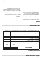
TABLE OF CONTENTS
IMPORTANT INFORMATION........................2
SPECIFICATIONS ..................................4
Table A: Gas Pressures...................................4
Table B: Model Designations .................................4
Table C: Input Rating ........................................9
INTRODUCTION .................................10
Uncratingl ..................................................10
Rating Plate ................................................10
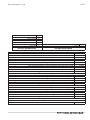
INSTALLATION...................................10
Clearances .................................................10
Installation Procedure ......................................10
Siting ......................................................11
Appliance Equipped With Casters ...........................11
Appliances Equipped With Legs ............................11
Installation Instructions for Cuisine Stub Backguard .........11
Installation Instructions for Cuisine Back Risers. .............12
Installation Instructions For Cuisine Single
And Double Deck High Shelves .............................12
Installation Instructions For
Cuisine Salamander or Cheese Melter .......................13
Statutory Regulations ......................................13
Gas Supply .................................................13
Gas Supply Notes: ..........................................14
Gas Connection ............................................14
Electrical Supply (Models with Convection Oven only) .......14
Assembly of Battery ........................................15
Ventilation And Air Supply ..................................15
COMMISSIONING ................................16
Pressure Regulators. ........................................16
Testing and Adjustments. ...................................16
Pressure Settings (All Models) ...............................16
Burner Adjustments ........................................16
Air Shutters............................................16
Thermostat Bypass Adjustment – Oven.................17
Pilot Burner Adjustments ...................................18
General................................................18
Oven ..................................................18
Solid Hot Plate/Griddle.................................18
Front Fired Hot Top ....................................18
Broiler.................................................18
OPERATION .....................................18
Open Top Burners ..........................................18
Hot top and Spectro-Top Sections ..........................18
Thermostatically Controlled Griddles .......................19
Valve Controlled Griddles ...................................19
Oven (Standard) ............................................19
“RC” Convection Ovens .................................... 20
Unit Broilers ................................................21
Fryers ......................................................21
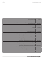
MAINTENANCE AND CLEANING...................21
Seasoning ..................................................21
Griddle Seasoning .....................................21
Seasoning Cast Iron top Grates.........................21
Cleaning ...................................................21
General Cleaning ......................................21
Stainless Steel Exterior and Standard Oven
Interior Finishes........................................22
Oven Interior (Optional Porcelain Enamel Finish)........22
Oven Interior Optional Continuous Clean Finish ........22
Griddle Cleaning.......................................23
Open Top Burners .....................................23
Cast Iron Top Grates....................................23
Cast Iron Hot tops and Spectro-Heat Tops ..............23
Broiler Cleaning ........................................... 24
C836-36A/C836-36ARC Models.........................24
C836-336A/C836-336ARC Models ......................24
C836-436A/C836-ARC Models..........................24
Adjustments .............................................. 24
Oven Orice ...........................................24
Pilot Adjustments......................................24
Automatic Pilot Valve ..................................25
Burner Gas/Air Adjustments............................25
CONVECTION OVEN PRODUCT APPLICATION . . . . . . 25
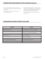
PROBLEM/SOLUTIONS CONVECTION OVEN........26
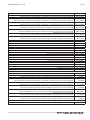
SERVICING ......................................27
Thermostat Calibration .................................... 27
Cleaning/Servicing Burners ................................ 27
Open-Type Burners ....................................27
Front Fired Solid Top Burners...........................27
Solid Hot Plate/Griddle Burners ........................27
Standard Oven Burners ................................28
RC Oven Burners.......................................28
Broiler.................................................28
Pilot Burner Cleaning ...................................... 28
Hot Plate/Solid Top/Griddle/Broiler.....................28
Oven ..................................................28
REPLACEMENT OF PARTS.........................29
Gas Valves ................................................. 29
Oven Thermostat .......................................... 29
Power Switch .............................................. 30
Door Switch ............................................... 30
Oven Pilot ................................................. 30
Convection Ovens (RC) - Spark Module ..................... 30
Convection Oven (RC) Motor ............................... 30
Hi-Limit Control ............................................31
Gas Control Valve ...........................................31
TROUBLESHOOTING GUIDE ......................32

Part # 3052000 (09/16/09)Page 4
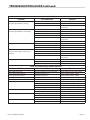
SPECIFICATIONS
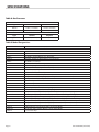
Table A: Gas Pressures
SUPPLY GAS PRESSURE RANGE
Type Minimum Maximum
Natural 7” W.C.( 17.5 mbar) 14” W.C. (35 mbar)
Propane 11” W.C. (27.5 mbar) 14” W.C. (35 mbar)
MANIFOLD OPERATING PRESSURE
Type Natural Propane
Ranges, Broilers 6”W.C. (15 mbar) 10” W.C. (25 mbar)
Table B: Model Designations
MODELS DESCRIPTION
Standard Oven Base
C836-1 36” Griddle
C836-1-1 36” Thermostatic Griddle
C836-2 24” Griddle, (2) Open Burners (12” Top Grate)
C836-2-1 24” Therm. Griddle, (2) Open Burners (12” Top Grate)
C836-3 24” Griddle, 12” Hot Top
C836-3-1 24” Therm. Griddle, 12” Hot Top
C836-4 18” Griddle, (2) Open Burners (18” Top Grate)
C836-4-1 18” Therm. Griddle, (2) Open Burners (18” Top Grate)
C836-5 18” Griddle, 18” Hot Top
C836-5-1 18” Therm. Griddle, 18” Hot Top
C836-6 Six Open Burners – (3) 12” Top Grates
C836-6SU Six Open Burners (3 Are Step-up) – (6) Half Top Grates (12” Inch Wide Each)
C836-7 Four Open Burners (2) 18” Top Grates
C836-8 (3) 12” Hot Tops
C836-9 (2) 18” Hot Tops
C836-10 (2) Front Fired Hot Tops
C836-11 18” Hot Top (Left), Front Fired Hot Top (Right)
C836-11R 18” Front Fired Hot Top (Left) 18” Hot Top (Right)
C836-12 (2) Open Burners, 12” Top Grate (Left), 12” Hot Top (Centre), 12” Hot Top (Right)
C836-12C 12” Hot Top (Left), (2) Open Burners 12” Top Grate (Centre), 12” Tog Grate (Right)
C836-12R 12” Hot Top (Left), 12” Hot Top (Centre), (2) Open Burners, 12” Top Grate (Right)
C836-13L 12” Hot Top (Left), 2) Open Burners, 12” Top Grate (Centre), (2) Open Burners, 12” Top
C836-13C (2) Open Burners, 12” Top Grate (Left), (2) Open Burners, 12” Top Grate (Centre), 12” Hot
C836-13 (2) Open Burners, 12” Top Grate (Left), (2) Open Burners, 12” Top Grate (Centre), 12” Hot
C836-14 (2) Open Burners, 18” Top Grate (Left), 18” Hot Top (Right)
C836-14L 18” Hot Top (Left), (2) Open Burners, 18” Top Grate (Right)
C836-15 (3) 12” French Tops

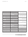
Part # 3052000 (09/16/09) Page 5
MODELS DESCRIPTION
Convection Oven Base
C836-1RC 36” Griddle
C836-1-1RC 36” Thermostatic Griddle
C836-2RC 24” Griddle, (2) Open Burners (12” Top Grate)
C836-2-1RC 24” Therm. Griddle, (2) Open Burners (12” Top Grate)
C836-3-RC 24” Griddle, 12” Hot Top
C836-3-1RC 24” Therm. Griddle, 12” Hot Top
C836-4-RC 18” Griddle, (2) Open Burners (18” Top Grate)
C836-4-1RC 18” Therm. Griddle, (2) Open Burners (18” Top Grate)
C836-5RC 18” Griddle, 18” Hot Top
C836-5-1RC 18” Therm. Griddle, 18” Hot Top
C836-6RC Six Open Burners – (3) 12” Top Grates
C836-6SURC Six Open Burners (3 Are Step-up) – (6) Half Top Grates (12” Inch Wide Each)
C836-7RC Four Open Burners (2) 18” Top Grates
C836-8RC (3) 12” Hot Tops
C836-9RC (2) 18” Hot Tops
C836-10RC (2) Front Fired Hot Tops
C836-11RC 18” Hot Top (Left), Front Fired Hot Top (Right)
C836-11RCR 18” Front Fired Hot Top (Left), 18” Hot Top Right
C836-12RC (2) Open Burners, 12” Top Grate (Left), 12” Hot Top (Centre), 12” Hot Top (Right)
C836-12CRC 12” Hot Top (Left), (2) Open Burners 12” Top Grate (Centre), 12” Hot Top (Right)
C836-12RRC 12” Hot Top (Left), 12” Hot Top (Centre), (2) Open Burners (Right), 12” Top Grate
C836-13LRC 12” Hot Top (Left, (2) Open Burners, 12” Top Grate (Centre), (2) Open Burners, 12” Top
C836-13CRC (2) Open Burners, 12” Top Grate (Left), 12” Hot Top (Centre), (2) Open Burners, 12” Top
C836-13RC (2) Open Burners, 12” Top Grate (Left), 2 Open Burners, 12” Top Grate (Centre), 12” Hot
C836-14RC (2) Open Burners, 18” Top Grate (Left), 18” Hot Top (Right)
C836-14RC 18” Hot Top (Left), (2) Open Burners, 18” Top Grate (Right
C836-15RC (3) 12” French Tops
Storage Base (Open Cabinet)
CO836-1 36” Griddle
CO836-1-1 36” Thermostatic Griddle
CO836-2 24” Griddle, (2) Open Burners (12” Top Grate)
CO836-2-1 24” Therm. Griddle, (2) Open Burners (12” Top Grate)
CO836-3 24” Griddle, 12” Hot Top
CO836-3-1 24” Therm. Griddle, 12” Hot Top
CO836-4 18” Griddle, (2) Open Burners (18” Top Grate)
CO836-4-1 18” Therm. Griddle, (2) Open Burners (18” Top Grate)
CO836-5 18” Griddle, 18” Hot Top
CO836-5-1 18” Therm. Griddle, 18” Hot Top
CO836-6 Six Open Burners – ((3) 12” Top Grates
CO836-6SU Six Open Burners (3 Are Step-up) – (6) Half Top Grates (12” Inch Wide Each)
CO836-7 Four Open Burners (2) 18” Top Grates
CO836-8 (3) 12” Hot Tops
CO836-9 (2) 18” Hot Tops
SPECIFICATIONS Continued

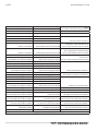
Part # 3052000 (09/16/09)Page 6
MODELS DESCRIPTION
Storage Base (Open Cabinet) Continued
CO836-10 (2) Front red Hot Tops
CO836-11 18” Hot Top (Left), Front Fired Hot Top (Right)
CO836-11R 18” Front Fired Hot Top (Left) 18” Hot Top (Right)
CO836-12
(2) Open Burners, 12” Top Grate (Left), 12” Hot Top (Centre), 12” Hot Top (Right)
CO836-12C
12” Hot Top (Left), (2) Open Burners 12” Top Grate (Centre), 12” Tog Grate (Right)
CO836-12R
12” Hot Top (Left), 12” Hot Top (Centre), (2) Open Burners, 12” Top Grate (Right)
CO836-13L 12” Hot Top (Left), 2) Open Burners, 12” Top Grate (Centre), (2) Open Burners, 12” Top
CO836-13C (2) Open Burners, 12” Top Grate (Left), (2) Open Burners, 12” Top Grate (Centre), 12” Hot
CO836-13 (2) Open Burners, 12” Top Grate (Left), (2) Open Burners, 12” Top Grate (Centre), 12” Hot
CO836-14 (2) Open Burners, 18” Top Grate (Left), 18” Hot Top (Right)
CO836-14L 18” Hot Top (Left), (2) Open Burners, 18” Top Grate (Right)
CO836-15 (3) 12” French Tops
Modular “T” Top (On Square Tubular Legs)
CO836-1M 36” Griddle
CO836-1-1M 36” Thermostatic Griddle
CO836-2M 24” Griddle, (2) Open Burners (12” Top Grate)
CO836-2-1M 24” Therm. Griddle, (2) Open Burners (12” Top Grate)
CO836-3M 24” Griddle, 12” Hot Top
CO836-3-1M 24” Therm. Griddle, 12” Hot Top
CO836-4M 18” Griddle, (2) Open Burners (18” Top Grate)
CO836-4-1M 18” Therm. Griddle, (2) Open Burners (18” Top Grate)
CO836-5M 18” Griddle, 18” Hot Top
CO836-5-1M 18” Therm. Griddle, 18” Hot Top
CO836-6M Six Open Burners – (3) 12” Top Grates
CO836-6MSU Six Open Burners (3 Are Step-up) – (6) Half Top Grates (12” Inch Wide Each)
CO836-7M Four Open Burners (2) 18” Top Grates
CO836-8M (3) 12” Hot Tops
CO836-9M (2) 18” Hot Tops
CO836-10M (2) Front Fired Hot Tops
CO836-11M 18” Hot Top (Left), Front Fired Hot Top (Right)
CO836-11RM 18” Front Fired Hot Top (Left), 18” Hot Top Right
CO836-12M (2) Open Burners, 12” Top Grate (Left), 12” Hot Top (Centre), 12” Hot Top (Right)
CO836-12CM 12” Hot Top (Left), (2) Open Burners 12” Top Grate (Centre), 12” Hot Top (Right)
CO836-12RM 12” Hot Top (Left), 12” Hot Top (Centre), (2) Open Burners (Right), 12” Top Grate
CO836-13LM 12” Hot Top (Left, (2) Open Burners, 12” Top Grate (Centre), (2) Open Burners, 12” Top
CO836-13CM (2) Open Burners, 12” Top Grate (Left), 12” Hot Top (Centre), (2) Open Burners, 12” Top
CO836-13M (2) Open Burners, 12” Top Grate (Left), 2 Open Burners, 12” Top Grate (Centre), 12” Hot
CO836-14CM (2) Open Burners, 18” Top Grate (Left), 18” Hot Top (Right)
CO836-14M 18” Hot Top (Left), (2) Open Burners, 18” Top Grate (Right
CO836-15M (3) 12” French Tops
SPECIFICATIONS Continued

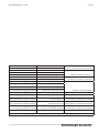
Part # 3052000 (09/16/09) Page 7
MODELS DESCRIPTION
Char-Broilers on Standard Oven Base
C836-336A Lava Rock W/Adjustable Grates – 36” Wide
C836-436A Cast Iron Radiants W/Adjustable Grates – 36” Wide
C836-36A Cast Iron Radiants W/Non-Adjustable Grates – 36” Wide
Char-Broilers on Convection Oven Base
C836-336ARC Lava Rock W/Adjustable Grates – 36” Wide
C836-436ARC Cast Iron Radiants W/Adjustable Grates – 36” Wide
C836-36ARC Cast Iron Radiants W/Non-Adjustable Grates – 36” Wide
Range Match Char-Broilers on Storage Base (Open Cabinet)
C0836-324A Lava Rock W/Adjustable Grates – 24” Wide
C0836-336A Lave Rock W/Adjustable Grates – 36” Wide
C0836-424A Cast Iron Radiants W/Adjustable Grates – 24” Wide
C0836-436A Cast Iron Radiants W/Adjustable Grates – 36” Wide
C0836-24A Cast Iron Radiants W/Non-Adjustable Grates – 24” Wide
C0836-36A Cast Iron Radiants W/Non-Adjustable Grates – 36” Wide
Modular “T” Top Char-Broilers on Square Tubular Legs
C0836-24AM Cast Iron Radiants W/Non-Adjustable Grates – 24” Wide
C0836-36AM Cast Iron Radiants W/Non-Adjustable Grates – 36” Wide
12” Wide, Add-A-Units with Storage Base (Open Cabine
t)
C12836-1 12” Griddle
C12836-1-1 12” Thermostatic Griddle
C12836-6 (2) Open Burners (12” Top Grate)
C12836-8 12” Hot Top
C12836-15 12” French Top
18” Wide, Add-A-Units with Modular Top/Square Tubular Legs)
C1836-1M 18” Griddle
C1836-1-1M 18” Thermostatic Griddle
C1836-7M (2) Open Burners (18” Top Grate)
C1836-9M 18” Hot Top
C1836-10M 18” French Top
18” Wide, Add-A-Units with Storage Base (Open Cabinets)
C1836-1 18” Griddle
C1836-1-1 18” Thermostatic Griddle
C1836-7 (2) Open Burners (18” Top Grate)
C1836-9 18” Hot Top
C1836-10 18” French Top
SPECIFICATIONS Continued

Part # 3052000 (09/16/09)Page 8
MODELS DESCRIPTION
Additional Griddle Models
48” Wide Units
C836-48 36” Std. Oven Base + 12” Storage Base + 48” Manual Griddle Top
C836-48-1 36” Std. Oven Base + 12” Storage Base + 48” Therm. Griddle Top
C836-48RC 36” RC Oven Base + 12” Storage Base + 48” Manual Griddle Top
C836-48-1RC 36” RC Oven Base + 12” Storage Base + 48” Therm. Griddle Top
CO836-48 36” Storage Base + 12” Storage Base + 48” Manual Griddle Top
C0836-48-1 36” Storage Base + 12” Storage Base + 48” Therm. Griddle Top
60” Wide Units
C836-60 36” Std. Oven Base + 24” Storage Base + 60” Manual Griddle Top
C836-60-1 36” Std. Oven Base + 24” Storage Base + 60” Therm. Griddle Top
C836-60RC 36” RC Oven Base + 24” Storage Base + 60” Manual Griddle Top
836-60-1RC 36” RC Oven Base + 24” Storage Base + 60” Therm. Griddle Top
CO836-60 36” Storage Base + 24” Storage Base + 60” Manual Griddle Top
C0836-60-1 36” Storage Base + 24” Storage Base + 60” Therm. Griddle Top
72” Wide Units
C2836-72 36” Std. Oven Base + 36” Std. Oven Base + 72” Manual Griddle Top
C2836-72RC 36” Std. Oven Base + 36” Rc Oven Base + 72” Manual Griddle Top
C2836-72RC2 36” RC Oven Base + 36” Oven Base + 72” Manual Griddle Top
C836-72 36” RC Oven Base + 36” Storage Base + 72” Manual Griddle Top
C836-72RC 36” RC Oven Base + 36” Storage Base + 72” Manual Griddle Top
CO836-72 36” Storage Base + 36” Storage Base + 72” Manual Griddle Top
C2836-72-1 36” Std. Oven Base + 36” Std. Oven Base + 72” Therm. Griddle Top
C2836-72-1RC 36” Std. Oven Base + 36” RC Oven Base + 72” Therm. Griddle Top
C2836-72-1RC2 36” Rc Oven Base + 36” RC Oven Base + 72” Therm. Griddle Top
C836-72-1 36” Std. Oven Base + 36” Storage Base + 72” Therm. Griddle Top
C836-72-1RC 36” Rc Oven Base + 36” Storage Base + 72” Therm. Griddle Top
CO836-72-1 36” Storage Base + 36” Storage Base + 72” Therm. Griddle Top
PREFIX DEFINITIONS: SUFFIX DEFINITIONS:
C Cuisine A Broiler
CO Cuisine Storage Base Or Modular Unit On Legs. M Modular Top Section
RC Unit With Convection Oven
R Right Hand
SU Step Up Burner
C Centre
L Left Hand
SPECIFICATIONS Continued

Part # 3052000 (09/16/09) Page 9
SPECIFICATIONS Continued
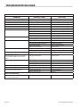
Table C: Input Rating
Model Number
GAS TYPE
Natural (@ 6”W.C.) Propane (@ 10”W.C.)
BTU/HR BTU/HR
Open Burner for Models: C836-2,-2-1,-4,-4-1,-6,-6SU,-7,-12,-12C, -12R,
-13,-13L,-13C,-14,-14L,-15(Front)
30,000 28,000
C836-15 Rear hot-top burner 15,000 15,000
C836-10,-11,-11R Front red hot top burner 12,500 12,500
C836-3,-3-1,-8,-12,-12C,-12R,-13-13L,-13C,-12” Hot top burner 25,000 25,000
C836-5,-5-1,-9,-11,-11R,-14,-14L 18” Hot top burner 32,500 32,500
C836-1,-1,-1,-2,-2-1,-3,-3-1,-4,-4-1,-5,-5-1 Griddle burner 30,000 30,000
C836 Oven burner (RC) 37,000 35,000
C836-336A,-324A, Broiler burner 45,000 45,000
C836-436A,-36A,-424A,-24A, Broiler burner 18,000 18,000
C836 Std oven burner 40,000 35,000
(Note: data applied to operation at elevation from sea level to 2000 ft)

Part # 3052000 (09/16/09)Page 10
INSTALLATION
INTRODUCTION
Uncratingl
1. Check crate for possible damage sustained during transit.
Carefully remove unit from crate and again check for
damage. Any damage to the appliance must be reported
to the carrier immediately.
2. The wires for retaining the burners and other packing
material must be removed from units. Any protective
material covering stainless steel parts must also be
removed.
3. All equipment is shipped from the factory with legs
tted, unless otherwise specied. Where the range is to
be mounted on a dial or cove base, it is shipped without
legs. Legs must be tted to the oven where it is installed
on a combustible oor.
4. The type of gas and supply pressure that the equipment
was set-up for at the factory is noted on the data plate
and on the packaging. This type of gas supply must be
used.
5. Do not remove permanently axed labels, warnings or
data plates from the appliance, for this may invalidate the
manufacturer’s warranty.
Rating Plate
Every cooking unit has a rating plate. Information on this
plate includes model and serial numbers. Knowing the
equipment model and serial number is essential if spare
parts are required or for discussing equipment problems
with Garland’s technical support sta. Other information
on the rating plate indicates BTU/hr output of the burners,
outlet gas pressure in inches water column (WC) and
whether orices are for natural or propane gas. The following
table gives the location of the rating plate on the designated
models, and Table B in the Specication Section lists the
various models of heavy duty equipment in the U.S. range
gas operated Cuisine series.
MODEL WITH SUFFIX LOCATION
Oven Or
Convection Oven Base
Behind the lower kick panel
Storage Cabinet Base
In the storage cabinet on
the left hand side panel
Modular Top On the front panel
NOTE: Cuisine heavy duty gas operated equipment must
be connected only to the type of gas identied on the rating
plate!
Clearances
MODELS CLEARANCES
C836-436A-436ARC
Installation in Non-
Combustible Locations
Only with 0” Side & Rear
Clearance
C836-36A-36ARC
C0836-324A,-336A
C0836-424A,-436A
C0836-24A,-36A
C0836-24AM,-36AM
All Other Models
7” (172mm )Side, 6”
(152mm) Rear, from
Combustible Base
1. All models may be installed with 0” side and rear
clearance from non-combustible construction.
2 For models sited on combustible and non-combustible
oor bases the required clearances are 7”(172mm) sides
and 6” (152mm) rear.
NOTE: When installed without legs on a non-combustible
curb or platform, front of unit should extend at least 3 inches
(76mm).
NOTE: Adequate clearance must be provided for servicing
and proper operation.
Installation Procedure
1. Remove all packing material.
2. Remove the front valve panel.

Part # 3052000 (09/16/09) Page 11
3. Place the appliance in the required position and level by
means of the adjustable feet, or shims if the appliance is
not equipped with legs.
4. Where spreader plates are installed between units the
plate is secured at the front by means of the gas manifold
and at the rear by means of the connecting bolts.
5. Connect the gas supply pipe work to the appliance. The
connection may be made to the left or right hand side of
the appliance or optionally at the rear on some models.
Siting
The oor on which the appliance is to be sited must be
capable of adequately supporting the weight of the
appliance and any ancillary equipment.
Units with ovens must be tted with legs if installed on a
combustible oor.
Appliance Equipped With Casters
A. The installation shall be made with a connector that
complies with the Standard for Connectors for Moveable
Gas Appliances, ANSI Z21.69/CSA 6.16, Addenda Z21.69B-
2006/CSA 6.16B-2006 (or latest edition), and a quick-
disconnect device that complies with the Standard for
Quick Disconnects for Use with Gas Fuel, ANSI Z21.41/
CSA 6.9, Addenda Z21.41A-2005/CSA 6.16A-2005 (or
latest edition).
B. The front casters of the unit are equipped with brakes
to limit the movement of the oven without depending
on the connector and any quick-disconnect device or its
associated piping to limit the appliance movement.
C. Please be aware, required restraint is attached to a
bracket (which is located on the left rear caster), and if
disconnection of the restraint is necessary, be sure to
reconnect the restraint after the appliance has been
returned to its originally installed position.
Appliances Equipped With Legs
Raise front of the unit and block. Do not lay unit on its back.
Position leg insert into leg retainer opening and tap up until
it seats at collar ange. Repeat at rear of unit making sure
all four legs are adjusted to the same height. Legs can be
adjusted to overcome an uneven oor.
INSTALLATION Continued
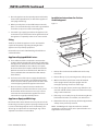
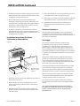
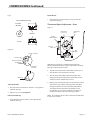
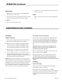
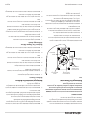
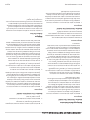
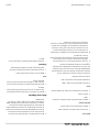
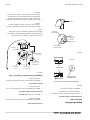
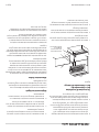
Installation Instructions for Cuisine
Stub Backguard
Figure 1
2
3
5
2
1
6
7
4
"X"
Oven Flue Riser
Optional right or
left side.
1. Remove four 5/16 hex bolts and at washers from top
rear of unit.
2. Remove ue cap (3), by removing #10-24, self tap screws.
3. With back and front panels (Item 4 & 5) still attached
to the uprights (Item 2) drop the uprights into the
rectangular openings at the rear of the range.
4. Fasten the uprights, (Item 2) to the range with four 5/16”
x 18 bolts and at washers, (Item 6 & 7 removed in step 1),
using a ratchet extension.
5. If the range is in a battery line-up, fasten units together at
hold marked “X” with 1/4” x 20 bolts, nuts and washers.
6. Reattach the ue cap (3) to the top of the backguard with
self tap screws previously removed.
NOTE: Stub Backguard is shipped installed as standard
equipment on all Cuisine units, unless optional back riser or
high shelf has been ordered.

Part # 3052000 (09/16/09)Page 12
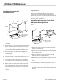
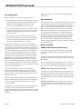
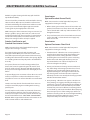
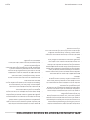
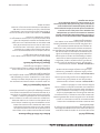
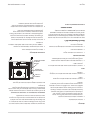
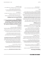
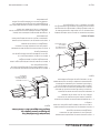
Installation Instructions for
Cuisine Back Risers.
Double Deck Risers
Figure 2
Shoulder
Bolts
2
"x"
7
6
5
5
4
3
1
Oven Flue Riser
Optional right or
left Side
1. Remove four 5/16 hex bolts and at washers from top
rear of unit.
2. Remove four #10 x 1 1/4” long sheet metal screws (Item 5)
from top and lower front corners of front panel. Remove
front panel by lifting upwards and pulling outward to
clear heads of shoulder bolts axed to uprights (Item 2).
3. With back panel, (3), still attached to the uprights, (2),
drop the uprights into the rectangular openings at the
rear of the range.
4. Fasten the uprights, (2), to the range with four, 5/16” x 18
bolts and at washers, (Item 6 & 7) removed in step one.
5. If the range is in a battery line-up fastens units together
at hold marked “X” with 1/4-20 bolts, nuts and washers.
6. Reattach the front panel by placing notches in back of
the front panel over heads of shoulder bolts and pulling
panel down until the top of the front panel rests on top
of uprights. This will allow shoulder bolts to lock panel
in-place. Re-install sheet metal screws (Item 5) previously
removed.
INSTALLATION Continued
Single Deck Risers:
Follow instructions above for double-deck backriser but
as there are no shoulder bolts involved in the single deck
assembly, the installation and removal of the front panel only
comprises assembly and disassembly of the four #10 x 1 1/4”
long sheet metal screws (Item 5).
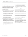
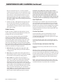
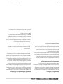
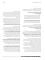
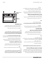
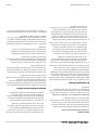
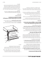
Installation Instructions For Cuisine Single
And Double Deck High Shelves
Figure 3
9
10
8
5
4
6
7
3
2
Oven Flue Riser
Optional right or
left side
1
"X"
1. Remove four 5/16” x 18 hex bolts and at washers from
top rear of unit (Item 6 & 7).
2. Remove four (4) 1/4-20 locking acorn nuts securing shelf
(Item 9). Remove shelf.
3. Remove (6) #10 sheet metal screws (Item 5) that ax
front panel (Item 4) to uprights (Item 2).
4. With back panel (3) still attached to uprights (2), drop the
uprights into the rectangular openings at the rear of the
range.
5. Fasten the uprights (2) to the range with four (4) 5/16” x
18 bolts and at washers previously removed.
6. If the appliance is in a battery line-up, fasten unit
together at hold marked “X” with 1/4 - 20 bolts, nuts and
washers.

Part # 3052000 (09/16/09) Page 13
7. Reattach the front panel by rst aligning clearance holes
with studs in uprights and then re-installing sheet metal
screws (Item 5) previously removed.
8. After installing front panel install shelf (Item 8) by
hooking the top of shelf over the top of the front panel.
Threaded studs on uprights will pass through clearance
holes on rear of shelf. Fasten shelf to studs via 1/4 - 20
locking acorn nuts provided (Item 9).
9. For double deck shelves, mount the lower shelf (one
with at back and no upper hook) to uprights through
front panel via locking nuts (Item 9) provided to 1/4” – 20
threaded studs on uprights.
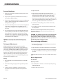
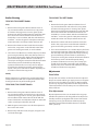
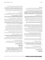
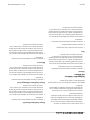
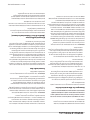
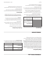
Installation Instructions For Cuisine
Salamander or Cheese Melter
Figure 4
2
"X"
Oven Flue Riser
Optional right or
left side
7
6
4
3
1
1. Remove four 5/16 x 18 hex bolts and at washers (Items 6
& 7) from rear top of unit.
2. Remove front panel, (4), by removing two, (2), sheet
metal screws from the underside of the salamander or
cheesemelter.
3. With back panel, (3), still attached to the uprights, (2),
drop the uprights into the rectangular openings at the
rear of the range.
4. Fasten the uprights (2), to the range with four, (4) 5/16” x
18 and at washers, (6 & 7) removed previously.
5. If the range is in a battery line-up, fasten units together at
hole marked “X” with 1/4 - 20 bolts, nuts and washers.
6. Reattach the front panel, (4) to the salamander or
Cheesemelter with sheet metal screws previously
removed.
Statutory Regulations
The installation of this appliance must be carried out by
a competent person and in accordance with the relevant
regulations, codes of practice and the related publications of
the country of destination.
Gas Supply
The local gas authority should be consulted at the
installation planning stage in order to establish the
availability of an adequate supply of gas and to ensure
that the meter is adequate for the required ow rate. The
pipe work from the meter to the appliances must be of an
appropriate size. Where a number of appliances are installed
in a battery, no more than ve should be served by any one
supply pipe.
All xed (non-mobile) appliances MUST be tted with a
manual gas cock-upstream of the appliance to provide a
means of isolation for servicing or cleaning purposes. A
union or similar means of disconnection must be provided
between the gas cock and the appliance.
A manually operable valve must be tted to the gas supply
to the kitchen to enable it to be isolated in a emergency.
Wherever the practical, this shall be located either outside
the kitchen or near to an exit in a readily accessible position.
Where it is not practical to do this, an automatic isolation
valve system shall be tted which can be operated from a
readily accessible position near to the exit.
At locations where the manual isolation valve is tted or
the automatic system can be reset a notice MUST be tted
stating:
“ALL DOWNSTREAM BURNER AND PILOT VALVES MUST
BE TURNED OFF PRIOR TO ATTEMPTING TO RESTORE THE
SUPPLY AFTER EXTENDED SHUT OFF, PURGE BEFORE
RESTORING GAS.”
INSTALLATION Continued

Part # 3052000 (09/16/09)Page 14
Gas Supply Notes:
Before assembly and connection check gas supply.
A. The type of gas for which the unit is equipped is stamped
on the data plate located behind the lower front panel.
Connect a unit stamped “NAT” only to natural gas;
connect one stamped “PRO” only to propane gas.
B. If it is a new installation have the gas authorities check
meter size and piping to assure that the unit is supplied
with the necessary amount of gas pressure required to
operate the UNIT.
C. If it is additional or replacement equipment have gas
authorities check pressure to make certain that existing
meter and piping will supply fuel to the unit with not
more than 1/2” water column pressure drop.
NOTE: When checking gas pressure be sure that all other
equipment on the same gas line is on. A pressure regulator
is not supplied as standard equipment with US Range Heavy
Duty Equipment, however a 1-1/4” pressure regulator is sold
as an option with the original purchase. If you would like to
purchase a regulator after original purchase contact your
equipment dealer. The installation must conform with the
national Fuel Gas Code ANSI Z 223.1 -1988 or latest edition,
NFPA No. 54 – latest edition and National Electrical Code
ANSI/NFPA 70-1990 or latest edition and/or local code to
assure safe and ecient operation. In Canada, the installation
must comply with CANICGA-149.1 Natural Gas Installation
Code, or CAN/CGA-B149.2 Propane Gas Installation code, and
local codes where applicable.
In Canada, electrical connection must comply with
applicable sections of the Canadian Electrical Code, C22.1
-1990, (or latest edition), “Safety Standard for Installation,
Part 1” and C22.2 – No. 0-M 1982; (or latest edition), “General
Requirements, Part 2”.
Note: The appliance and its individual shut-o valve must be
disconnected from the gas supply piping system during any
pressure testing of that system at pressures in excess of
1/2 PSIG (3.45 kPa).
The appliance must be isolated from the gas supply piping
system by closing its individual manual shut-o (not
supplied with appliance) during any testing of the gas supply
piping system at test pressures equal to or less than 1/2 PSIG
(3.45kPa).
INSTALLATION Continued
NOTE: This appliance is not recommended for residential
installation.
Gas Connection
The gas pipe connection is made at the left hand side or right
hand side of the equipment or optionally at rear on some
units. The size of the pipe work supplying the appliance must
not be less than the inlet connection, which is 1 1/4” NPT.
(Note: a 3/4” NPT single unit optional connection must be
specied.) An isolating valve is recommended to be close
to and upstream of the appliance and regulator to allow
shutdown during an emergency or routine servicing. A gas
pressure regulator must be installed at the appliance prior
to connecting the equipment to the gas supply (service)
line. Failure to install a regulator will void the equipment
warranty. After installation, be certain to check the complete
pipe work for leakage.
Electrical Supply
(Models with Convection Oven only)
The electrical supply required is single phase, 115V, 60Hz.
As an option, equipment can be supplied for 240V, 60Hz
operation.
If 240V, the supply must be connected to the terminal block
termination located at the rear of the range for models with
the sux RC.
For ease in attaching the supply line, there is a removable
cover. A qualied electrician should make the connection to
the mains in accordance with the applicable local codes.
WARNING: Electrical Grounding Instructions.
This appliance is equipped with a three prong (grounding)
plug for your protection against shock hazard and should
be plugged directly into a properly grounded three-prong
receptacle. Do not cut or remove the grounding prong from
this plug.
POWER FAILURE NOTE: In the event of a power failure, no
attempt should be made to operate this oven. This oven is
gas operated but has electrical features, motor and door
switches.

Part # 3052000 (09/16/09) Page 15
Assembly of Battery
All models described except Models C836-336A, C836-436A,
C836-336ARC, C836-436ARC and C836-110 may be installed
to battery with Cuisine Series Ranges, sharing common
manifold connections. Models C836-336A, C836-336ARC,
C836-436A and C836-436ARC range base broilers may be
connected to other like broilers, but cannot be placed in a
battery with other cuisine units.
A. All such units should be placed in their respective battery
position. Detach valve panels to prevent damage and
remove them from the area where the battery is being
assembled.
B. Level each unit (to the front rail) by adjusting the six inch
(6”) legs or where legs are not used, adjust level with
shims. Readjust legs, if required.
C. Connect units together by mating the unions at each
end of the manifold. (Adjoining units must have
matching unions, unless the union parts are of the
same specications, a leak proof connection cannot be
assured.) Hand tighten unions at this point.
D. The units should be fastened at the rear by inserting 5/16”
bolts through the holes provide at the rear of the burner
box sides. Install washer and nut and hand tighten. Be
sure of proper unit alignment in the battery before nal
tightening of these bolts or unions, improper tightening
will cause “fanning” or “bowing” of batteried units.
The nal tightening of the union should be accomplished
by using a suitable spanner wrench. If such a wrench
is not available, the GARLAND union collar has special
ridges, and a cold chisel can be driven against these
ridges to properly seat and seal the union.
INSTALLATION Continued
E. The manifold of this unit or the manifold of which it is
a part of must be equipped with a certied pressure
regulator suitable for battery application and adjustable
for an outlet pressure at the manifold as specied on the
rating plate.
Ventilation And Air Supply
Proper ventilation is highly important for good operation.
The ideal method of ventilating a range is the use of
a properly designed canopy which should extend
approximately six inches (6”, 152 mm) beyond all sides of the
appliance and six feet (6’) six inches (6”), (1981mm) from the
oor.
A strong exhaust fan will create a vacuum in the room. For an
exhaust system vent to work properly, replacement air must
enter the room in which the vent is located.
All gas burners and pilots need sucient air to operate and
large objects should not be placed in front of the appliance
which would obstruct the airow through the front.
The following notes are intended to give general guidance.
For detailed recommendations, refer to the applicable
code(s) in the country of destination.
NOTE 1: The room containing the appliance is required to
have a permanent air vent. The minimum eective area of
the vent is related to the maximum rated heat input of the
appliance and shall be 4.5 cm² per kW (2.04 X 10 in² per
BTU/H) in excess of 7 kW. (23,900 BTU/H).
NOTE 2: Air vents should be of such a size to compensate for
the eects of any extract fan in the premises.

Part # 3052000 (09/16/09)Page 16
COMMISSIONING
Pressure Regulators.
1. Must have a maximum regulation capacity for the total
connected load.
2. The pressure regulator(s) installed must be listed by a
nationally recognized agency.
3. The pressure regulators must have a pressure adjustment
range to allow adjustment to the manifold pressure on
the appliance rating plate.
4. Unless the manifold pressure on all connected appliances
is the same, a separate pressure regulator must be
supplied for each appliance having diering manifold
pressures.
5. Gas supply lines may be connected at right, left or both
ends of a battery or at the TEE connections on spreader
plates. If ve (5) or more units are placed in a battery,
more than one (1) supply line should be used. A readily
accessible, approved type of hand shut-o valve should
be installed on each supply line.
WARNING: Local codes may require that the pressure
regulator be externally vented. This will be supplied by
others.
Testing and Adjustments.
All ttings and pipe connections must be tested for
leaks. Use approved gas leak detectors, soap solutions or
equivalent, checking over and around the ttings and pipe
connections. DO NOT USE A FLAME! Accessibility to all gas
lines and ttings require that valve panel(s), lower front
panel(s), oven rack(s) be removed. It may be necessary to
remove or at least raise and securely prop-griddles, hot
tops and top grates. All parts removed (including fasteners)
should be stored safely for re-use.
Testing
1. Be sure that all valves and thermostats are in the “OFF”
position.
2. Turn on the main gas supply valve. Light all top section
pilots.
3. Leak test all valves and ttings as described in the
procedure above. Correct any leaks as required and
recheck.
4. Light oven pilot.
5. If the range is provide with an oven shut-o valve
separate from the thermostat, turn this valve on and set
the thermostat at 500°F (260°C) degrees. If the range
oven thermostat has an “OFF” position on the dial the
thermostat is equipped with an internal, integral shut-o
valve. Set this thermostat dial to 500°F (260°C) degrees. In
both cases, gas will now ow to the oven burner.
6. Leak test all valves, ttings, etc, as above. Correct any
leaks and retest.
7. Shut o all rang valves and set thermostat dials to “OFF”
or low position.
All units are tested and adjusted at the factory. However,
burners and pilots should be checked at installation and
adjusted if necessary.
CAUTION: Gas will ow to top burners even with top pilots
out. Gas will not be interrupted. It is the responsibility of
the operator to check the ignition of the burners. Should
ignition fail after ten (1) seconds, turn burner valve o and
wait ve (5) minutes and then try again.
Pressure Settings (All Models)
1. Make sure all gas valves are in the OFF position and turn
on the main gas supply.
2. Light all pilots in accordance with the User’s Instructions.
3. Connect a U-gauge manometer to the pressure test point
on the main manifold and turn all gas controls to the ON
position.
Conrm that the pressure is the same as stated on the rating
plate.
Burner Adjustments
Air Shutters
Open Top Section
1. Check that the air shutter is set to the required opening.
(Refer to gure 6)
2. Adjust setting as necessary.

Part # 3052000 (09/16/09) Page 17
COMMISSIONING Continued
Fig 5
INJECTOR
LOCATION
OPENING
CUISINE BURNER SHUTTER
SKSHUT
Figure 6
Injector Location
Fixing Screw
Required Length
of Opening
Aeration
Shutter
Opening
Solid Top/Griddle
1. Check to make sure that the air shutter is set to give the
required opening.
2. Adjust as necessary (See Figure 6)
Front Fired Solid Top,
1. Check that the aeration shutter is set to provide the
required opening.
Broiler Burner
1. Check that the aeration shutter is set to provide the
requested opening.
Thermostat Bypass Adjustment – Oven
Figure 7
R
O
B
E
R
T
S
H
A
W
MODEL
FDO
1/2 PSI
By-Pass
Flame Adjuster
Indicator
Mark
Calibration
Lock Screw
Calibration
Plate
Dial
Stop
With reference to Figure 7, the Robertshaw FDO snap-
throttle thermostat requires a bypass adjustment. To adjust
the bypass, follow this procedure.
1. Turn the oven temperature control dial to 200°F (93° C)
then allow the oven to heat for 3 minutes.
2. Turn the oven control dial to the OFF position, then
slowly turn the oven temperature control dial counter-
clockwise until an audible click is heard.
3. Making sure not to disturb the oven temperature control
dial, turn the bypass ame adjusting screw and adjust
the bypass ame to the Lowest Possible Stable ame
covering the Entire Ported Area of the Burner. Turn
the adjusting screw counter-clockwise to increase or
clockwise to decease the size of the bypass ame.
NOTE: For calibration please refer to Thermostat Calibration
in the Service Section.

Part # 3052000 (09/16/09)Page 18
Pilot Burner Adjustments
General
1. Light the pilot light in accordance with the Operation
Instructions in Operation Section.
2. Check that the length of the ame and adjust as
necessary for desired characteristics. Screwdriver
adjustment may be made to the pilot valve adjacent
to the burner valve on the manifold, through the valve
panel opening.
Oven
1. Open the lower kick panel.
2. Remove the oven bottom assembly.
3. Light the pilot light in accordance with the Operations
Instructions.
4. Check that the length of the pilot light. Adjust pilot ame
for desired characteristics. Screwdriver adjustments may
be made to the pilot valve, adjacent to the oven burner
valve on the manifold, through the valve panel opening.
COMMISSIONING Continued
Solid Hot Plate/Griddle
1. Light the pilot in accordance with the Operation
Instructions.
2. Check that the length of the ame. Adjust pilot ame for
desired characteristics. Screwdriver adjustment may be
made to the pilot valve adjacent to the burner valve on
the manifold through the valve panel opening.
Front Fired Hot Top
1. Light the pilot light in accordance with the Operation
Instructions.
2. Check that the length of the ame. Adjust pilot ame for
desired characteristics. Screwdriver adjustment may be
made to the pilot valve adjacent to the burner valve on
the manifold through the valve panel opening.
Broiler
1. Light the pilot light in accordance with the Operation
Instructions.
2. Check that the length of the ame. Adjust pilot ame for
desired characteristics. Screwdriver adjustment may be
made to the pilot valve adjacent to the burner valve on
the manifold through the valve panel opening.
OPERATION
This section deals with equipment operating instructions
and some of the simple and obvious cleaning methods
that will help keep heavy duty cooking equipment in good
condition.
Open Top Burners
1. Open top burner pilots may be reached down through
the opening of the top grate.
2. Light the pilots.
3. Turn the valve completely on by rotating the knob to the
“ON” position.
NOTE: The burner ame should be a 1/2” stable ame and
impinge on the underside of a pot placed on the top grate.
Shutdown
1. Turn all valves to the o position.
2 If the unit is to be shut down for an extended time, close
the in-line gas valve.
Hot top and Spectro-Top Sections
1 Light the pilots via a long match or taper through the
opening in the valve panel.
2. Turn the burner valve on by rotating the knob to the “ON”
position. A sharp blue ame should be approximately
1/4” high.

Part # 3052000 (09/16/09) Page 19
Shutdown
1. Turn all valves to the o position.
If the unit is to be shut down for an extended time, close the
in-line gas valve.
Thermostatically Controlled Griddles
1. Light the pilots at the front right side of the burner via
a long match or tape through the opening in the valve
panel.
2. Set the thermostat to maximum one at a time. The burner
should have a 5/16” high stable ame.
CAUTION: Do not allow the griddle to heat for longer than
one minute. The griddle must be seasoned before use.
(Refer to the Passage Entitled “Griddle Seasoning”).
Shut Down
1 Turn all thermostat valves to the OFF position.
2 If the unit is to be shut down for an extended time, close
the in-line gas valve.
Valve Controlled Griddles
1. Light the pilot at the front right side of the burner via a
long match or taper through the opening in the valve
panel.
2. Turn the burners on by rotating them to the “ON”
position. The burners should have a 1/2” to 5/8” stable
blue ame.
CAUTION: Do not allow the griddle to heat for longer than
one minute. The griddle must be seasoned before use.
(Refer to the Passage Entitled “Griddle Seasoning”).
Shut Down
1. Turn all valves to the OFF position.
2. If the unit is to be shut down for an extended time, close
the in-line gas valve.
OPERATION Continued
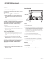
Oven (Standard)
INS. PLATE
SERIAL PLATE
OVEN
THERMOSTAT
RED
RESET
BUTTON
Lighting
1. Remove Oven bottom.
2. Depress and hold reset button (red) located through the
access hole on the front control panel to the left of the
oven door (When facing the unit front.) While lighting the
oven pilot, continue to depress the reset button for 60
seconds. Release button. If pilot does not stay lit, repeat
this procedure after 5 minutes.
3. Turn oven valve knob to the “ON” position.
4. Rotate oven thermostat dial to the desired setting.
Shut Down
1. Turn oven valve and thermostats to, the o position.
2. If range is to be shut down for an extended period of
time, close the in line gas valve.
Relighting
1. Shut all gas valves o.
2. Wait 5 minutes.
3. Repeat lighting instructions in lighting above.

Part # 3052000 (09/16/09)Page 20
“RC” Convection Ovens
For 115 V usage, a cord and plug is provided but connection
to the electrical service must comply with local codes; or in
the absence of local codes with the National electrical code,
ANSI/NFPA No. 70-(or current edition).
WARNING:
Electrical Grounding Instructions.
This appliance is equipped with a three pronged (grounding)
plug for your protection against shock hazard and should be
plugged directly into a properly grounded three-pronged
receptacle. Do not cut or remove the grounding prong from
this plug.
POWER FAILURE NOTE: In the event of a power failure, no
attempt should be made to operate this oven. This oven is
gas operated but has electrical features, motor and door
switches.
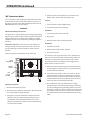
A wiring diagram is attached to the rear of this unit.
INS. PLATE
SERIAL PLATE
OVEN
THERMOSTAT
POWER
SWITCH
RED
RESET
BUTTON
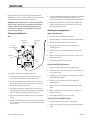
Lighting Instructions
1. Remove the lower front panel.
2. Push the power switch to cook position. This will activate
the spark module and light the pilot.
3. Using the access hole in the front control panel to the
left of the oven door (when facing unit front) depress
and hold the reset button (Red) located on the oven
safety valve. Continue to depress the reset button for 60
seconds. Release button.
OPERATION Continued
4. If the pilot does not stay lit after you release the reset
button, wait 5 minutes and repeat Step 3 & 4.
Start Up
1. Turn oven knob on to the “ON” position.
2. Turn thermostat to desired setting.
Cool Down
1. Turn thermostat and oven valve o.
2. Open Door.
3. Activate power to the cool down position.
Shut Down
1. Turn thermostat o.
2. Return power switch to “OFF” position.
3. Turn oven valve o.
The motor on your range convection oven is maintenance
free since it is constructed with self lubricating sealed ball
bearings. It is designed to provide durable service when
treated with ordinary care. We have a few suggestions to
follow on the care of your motor.
A. When the motor is operating, it cools itself internally by
air entering the rear of the motor case, provided proper
clearance has been allowed.
B. Since the blower wheel is in the oven cavity it is at the
same temperature at the oven. If the motor is stopped
while the oven is hot, the heat from the blower wheel is
conducted down the shaft and into the armature of the
motor. This action could shorten motor life.
C. We recommend, at the end of the bake or roasting
period, when the oven will be idle for any period of time
or before shutting down completely, that the oven door
be left open, and by use of the cool-down position on the
fan switch, the fan continue to run for at least 20 minutes.
The “FAN” should never be turned “OFF” when the oven is
“HOT”.
La page est en cours de chargement...
La page est en cours de chargement...
La page est en cours de chargement...
La page est en cours de chargement...
La page est en cours de chargement...
La page est en cours de chargement...
La page est en cours de chargement...
La page est en cours de chargement...
La page est en cours de chargement...
La page est en cours de chargement...
La page est en cours de chargement...
La page est en cours de chargement...
La page est en cours de chargement...
La page est en cours de chargement...
La page est en cours de chargement...
La page est en cours de chargement...
La page est en cours de chargement...
La page est en cours de chargement...
La page est en cours de chargement...
La page est en cours de chargement...
La page est en cours de chargement...
La page est en cours de chargement...
La page est en cours de chargement...
La page est en cours de chargement...
La page est en cours de chargement...
La page est en cours de chargement...
La page est en cours de chargement...
La page est en cours de chargement...
La page est en cours de chargement...
La page est en cours de chargement...
La page est en cours de chargement...
La page est en cours de chargement...
La page est en cours de chargement...
La page est en cours de chargement...
La page est en cours de chargement...
La page est en cours de chargement...
La page est en cours de chargement...
La page est en cours de chargement...
La page est en cours de chargement...
La page est en cours de chargement...
La page est en cours de chargement...
La page est en cours de chargement...
La page est en cours de chargement...
La page est en cours de chargement...
La page est en cours de chargement...
La page est en cours de chargement...
La page est en cours de chargement...
La page est en cours de chargement...
La page est en cours de chargement...
La page est en cours de chargement...
La page est en cours de chargement...
La page est en cours de chargement...
-
 1
1
-
 2
2
-
 3
3
-
 4
4
-
 5
5
-
 6
6
-
 7
7
-
 8
8
-
 9
9
-
 10
10
-
 11
11
-
 12
12
-
 13
13
-
 14
14
-
 15
15
-
 16
16
-
 17
17
-
 18
18
-
 19
19
-
 20
20
-
 21
21
-
 22
22
-
 23
23
-
 24
24
-
 25
25
-
 26
26
-
 27
27
-
 28
28
-
 29
29
-
 30
30
-
 31
31
-
 32
32
-
 33
33
-
 34
34
-
 35
35
-
 36
36
-
 37
37
-
 38
38
-
 39
39
-
 40
40
-
 41
41
-
 42
42
-
 43
43
-
 44
44
-
 45
45
-
 46
46
-
 47
47
-
 48
48
-
 49
49
-
 50
50
-
 51
51
-
 52
52
-
 53
53
-
 54
54
-
 55
55
-
 56
56
-
 57
57
-
 58
58
-
 59
59
-
 60
60
-
 61
61
-
 62
62
-
 63
63
-
 64
64
-
 65
65
-
 66
66
-
 67
67
-
 68
68
-
 69
69
-
 70
70
-
 71
71
-
 72
72


Garland E20 Series Owner Instruction Manual
- Catégorie
- Cuisinières
- Taper
- Owner Instruction Manual
dans d''autres langues
- English: Garland E20 Series
Documents connexes
-
Garland Regal Series Manuel utilisateur
-
-
Garland E20 Series Owner Instruction Manual
-
-
Garland MST44 Mode d'emploi
-
-
Garland M100XR Mode d'emploi
-
-
-
Autres documents
-
Vulcan VCRG36-T Le manuel du propriétaire
-
Vulcan-Hart MSA48-ML-135238 Manuel utilisateur
-
Vulcan 960RX Le manuel du propriétaire
-
Vulcan 36S-36CB Le manuel du propriétaire
-
Vulcan-Hart ML-136590 Manuel utilisateur
-
Livoo DOC278 Manuel utilisateur
-
Vulcan-Hart GHIR44-ML-52210 spécification
-
Vulcan 36RB Manuel utilisateur
-
Wolf Range WCRG36-T Mode d'emploi
-
Vulcan-Hart GHX60T Manuel utilisateur