Winmate W10L100-GSH2 Guide de démarrage rapide
- Taper
- Guide de démarrage rapide

Please read these instructions carefully before using this product, and save this manual for future use
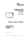
G-WIN Slim IP65
P-CAP Display
W07L100-GSO1
W10L100-GSH1(HB)
R10L100-GST2
R12L100-GSM2(HB)
R15L600-GSC3(HB)
Quick Start Guide
V1.1
For more information on this and
other Winmate products, please
visit our website at:
www.winmate.com
Document Part Number: 91521110100Q

- 2 -
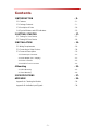
Contents
1 INTRODUCTION - 8 -
1.1 Features - 8 -
1.2 Package Contents - 9 -
1.3 Description of Parts - 10 -
1.4 Physical Buttons and LED Indicators - 15 -
2 GETTING STARTED - 17 -
2.1 Turning On Your Device - 17 -
2.2 Turning Off Your Device - 18 -
3 INSTALLATION - 19 -
3.1 Wiring Requirements - 19 -
3.2 Connecting to Other Devices - 20 -
3.3 Connector Description - 21 -
3.3.1 Power Input Connector - 21 -
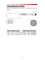
3.3.2 AC Adapter (For 7” Display) - 22 -
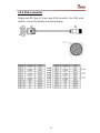
3.3.3 VGA Connector - 23 -
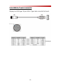
3.3.4 USB for Touch Connector - 24 -
4 Mounting - 25 -
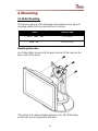
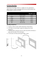
4.1 VESA Mounting - 25 -
4.2 Panel Mounting - 26 -
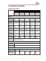
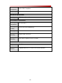
5 SPECIFICATIONS - 27 -
APPENDIX - 29 -
Appendix A: Cleaning the Monitor - 29 -
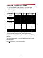
Appendix B: Available Input Signals - 30 -

- 3 -
FCC Statement
This device complies with part 15 FCC rules.
Operation is subject to the following two
conditions:
This device may not cause harmful
interference.
This device must accept any interference
received including interference that may
cause undesired operation.
This equipment has been tested and found to comply with the
limits for a class "B" digital device, pursuant to part 15 of the FCC
rules. These limits are designed to provide reasonable protection
against harmful interference when the equipment is operated in a
commercial environment. This equipment generates, uses, and
can radiate radio frequency energy and, if not installed and used in
accordance with the instruction manual, may cause harmful
interference to radio communications. Operation of this equipment
in a residential area is likely to cause harmful interference in which
case the user will be required to correct the interference at him
own expense.

- 4 -
European Union
Electromagnetic Compatibility Directive
(2014/30/EU)
EN55024: 2010/ A1: 2015
o IEC61000-4-2: 2009
o IEC61000-4-3: 2006+A1: 2007+A2: 2010
o IEC61000-4-4: 2012
o IEC61000-4-5: 2014
o IEC61000-4-6: 2014
o IEC61000-4-8: 2010
o IEC61000-4-11: 2004
EN55032: 2012/AC:2013
EN61000-3-2:2014
EN61000-3-3:2013
Low Voltage Directive (2014/35/EU)
EN 60950-1:2006/A11:2009/A1:2010/A12:2011/
A2:2013
This equipment is in conformity with the requirement of the
following EU legislations and harmonized standards. Product also
complies with the Council directions.

- 5 -
Copyright Notice
No part of this document may be reproduced, copied, translated, or
transmitted in any form or by any means, electronic or mechanical, for
any purpose, without the prior written permission of the original
manufacturer.
Trademark Acknowledgement
Brand and product names are trademarks or registered trademarks of
their respective owners.
Disclaimer
Winmate Inc. reserve the right to make changes, without notice, to
any product, including circuits and/or software described or contained
in this manual in order to improve design and/or performance. We
assume no responsibility or liability for the use of the described
product(s) conveys no license or title under any patent, copyright, or
masks work rights to these products, and make no representations or
warranties that these products are free from patent, copyright, or
mask work right infringement, unless otherwise specified. Applications
that are described in this manual are for illustration purposes only. We
make no representation or guarantee that such application will be
suitable for the specified use without further testing or modification.
Warranty
Winmate Inc. warranty guarantees that each of its products will be
free from material and workmanship defects for a period of one year
from the invoice date. If the customer discovers a defect, we will, at
his/her option, repair or replace the defective product at no charge to
the customer, provide it is returned during the warranty period of one
year, with transportation charges prepaid. The returned product must
be properly packaged in its original packaging to obtain warranty
service. If the serial number and the product shipping data differ by
over 30 days, the in-warranty service will be made according to the
shipping date. In the serial numbers the third and fourth two digits
give the year of manufacture, and the fifth digit means the month (e.
g., with A for October, B for November and C for December).
For example, the serial number 1W16Axxxxxxxx means October of
year 2016.

- 6 -
Customer Service
We provide a service guide for any problem by the following steps:
First, visit the website of our distributor to find the update information
about the product. Second, contact with your distributor, sales
representative, or our customer service center for technical support if
you need additional assistance.
You may need the following information ready before you call:
Product serial number
Software (OS, version, application software, etc.)
Description of complete problem
The exact wording of any error messages
In addition, free technical support is available from our engineers
every business day. We are always ready to give advice on
application requirements or specific information on the installation and
operation of any of our products.

- 7 -
Safety Information
WARNING! / AVERTISSEMENT!
Always completely disconnect the power cord from your
chassis whenever you work with the hardware. Do not
make connections while the power is on. Sensitive
electronic components can be damaged by sudden
power surges. Only experienced electronics personnel
should open the PC chassis.
Toujours débrancher le cordon d’alimentation du chassis
lorsque vous travaillez sur celui-ci. Ne pas brancher de
connections lorsque l’alimentation est présente. Des
composantes électroniques sensibles peuvent être
endommagées par des sauts d’alimentation. Seulement
du personnel expérimenté devrait ouvrir ces chassis.
CAUTION/ATTENTION
Always ground yourself to remove any static charge
before touching the CPU card. Modern electronic
devices are very sensitive to static electric charges. As a
safety precaution, use a grounding wrist strap at all
times. Place all electronic components in a static-
dissipative surface or static-shielded bag when they are
not in the chassis.
Toujours verifier votre mise à la terre afin d’éliminer
toute charge statique avant de toucher la carte CPU.
Les équipements électroniques moderns sont très
sensibles aux décharges d’électricité statique. Toujours
utiliser un bracelet de mise à la terre comme précaution.
Placer toutes les composantes électroniques sur une
surface conçue pour dissiper les charge, ou dans un sac
anti-statique lorsqu’elles ne sont pas dans le chassis.

- 8 -
1 INTRODUCTION
Congratulations on purchasing Winmate® G-WIN Slim IP65 P-CAP
Display. The elegantly designed, yet rugged, industrial grade G-WIN
S65 series is designed for usability with brilliant true-flat screens,
which offer superior readability and Projected Capacitive Multi-Touch
(P-CAP) technology, available in 7”, 10.1”, 10.4”, 12.1” and 15”
options.
G-WIN Slim IP65 Display features Projected Capacitive Multi-Touch
(P-CAP). These models are full IP 65 dustproof and waterproof and
have M12 connectors.
1.1 Features
Winmate® G-WIN Slim IP65 with P-CAP Display features:
7”, 10.1”, 10.4”, 12.1” and 15” LCD
Projected Capacitive Multi-Touch (P-CAP)
Full IP65 rating
Wide operating temperature -10°C~55°C
M12 connectors: 12V DC, 1 x VGA, 1 x USB for Touch

- 9 -
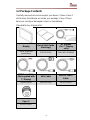
1.2 Package Contents
Carefully remove the box and unpack your device. Please check if
all the items listed below are inside your package. If any of these
items are missing or damaged contact us immediately.
Standard factory shipment list:
Display
Quick Start Guide
(Hardcopy)
AC Adapter
(For 7” Display
only)
Varies by product
specifications
91521110100Q
50W: 90PO12050006
M12 Power Cable
(Not supplied with
7” Display)
VGA Cable
USB for Touch
Cable
94J003L020K8
9441150120Q0
94E0127040K0
I/O Protective
Cap x 3
60Y031131000

- 10 -
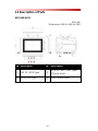
1.3 Description of Parts
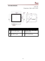
W07L100-GSO1
Unit: mm
Dimensions: 189.4 x 145.4 x 39.8
№
Description
№
Description
12V DC (M12 Type)
USB for Touch (M12 Type)
*Only for touch
VGA (M12 Type)
OSD Control Panel

- 11 -
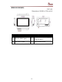
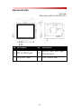
W10L100-GSH1(HB)
Unit: mm
Dimensions: 263.28 x 173.6 x 40.2
№
Description
№
Description
12V DC (M12 Type)
USB for Touch (M12 Type)
*Only for touch
VGA (M12 Type)
OSD Control Panel

- 12 -
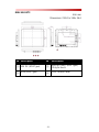
R10L100-GST2
Unit: mm
Dimensions: 252.61 x 198 x 36.4
№
Description
№
Description
12V DC (M12 Type)
USB for Touch (M12 Type)
*Only for touch
VGA (M12 Type)
OSD Control Panel

- 13 -
R12L100-GSM2(HB)
Unit: mm
Dimensions: 296.2 x 226.7 x 45.5
№
Description
№
Description
12V DC (M12 Type)
USB for Touch (M12 Type)
*Only for touch
VGA (M12 Type)
OSD Control Panel

- 14 -
R15L600-GSC3(HB)
Unit: mm
Dimensions: 363.4 x 277.86 x 45.2
№
Description
№
Description
12V DC (M12 Type)
USB for Touch (M12 Type)
*Only for touch
VGA (M12 Type)
OSD Control Panel

- 15 -
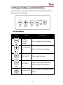
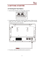
1.4 Physical Buttons and LED Indicators
Physical buttons and LED indicators (OSD Control Panel) located on
the rear side of the Display.
Physical Buttons
Icon
Button
Description
DOWN/
VOLUME
DOWN
Press to lower down the volume
UP/ VOLUME
UP
Press to increase the volume
ESC/ AUTO
Press to exit the menu
OK/ MENU
Press to confirm the action or to
come back to the main menu
Power On/ Off
Press to power on or power off the
device

- 16 -
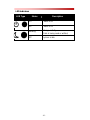
LED Indicators
LED Type
Status
Description
On
Power is on
Off
Power is off
Blinking
Storage activity
(Data is being read or written)
Off
System is idle

- 17 -
2 GETTING STARTED
2.1 Turning On Your Device
1. Remove the protective cap of the power connector.
2. Connect power cable to the connector of your device. Make sure the
cable fits to the connector, then tighten the O-ring (by turning
clockwise) to secure the connection.
3. The device will boot automatically when powered on.

- 18 -
2.2 Turning Off Your Device
Disconnect the power cord from the Display to completely turn off the
device.

- 19 -
3 INSTALLATION
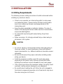
3.1 Wiring Requirements
The following common safety precautions should be observed before
installing any electronic device:
Strive to use separate, non-intersecting paths to route power
and networking wires. If power wiring and device wiring paths
must cross make sure the wires are perpendicular at the
intersection point.
Keep the wires separated according to interface. The rule of
thumb is that wiring that shares similar electrical characteristics
may be bundled together.
Do not bundle input wiring with output wiring. Keep them
separate.
When necessary, it is strongly advised that you label wiring to
all devices in the system.
CAUTION
Do not run signal or communication wiring and power wiring in
the same conduit. To avoid interference, wires with different
signal characteristics (i.e., different interfaces) should be routed
separately.
Be sure to disconnect the power cord before installing and/or
wiring your device.
Verify the maximum possible current for each wire gauge,
especially for the power cords. Observe all electrical codes
dictating the maximum current allowable for each wire gauge.
If the current goes above the maximum ratings, the wiring could
overheat, causing serious damage to your equipment.
Be careful when handling the unit. When the unit is plugged in,
the internal components generate a lot of heat which may leave
the outer casing too hot to touch.

- 20 -
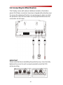
3.2 Connecting to Other Devices
This Display comes with various interfaces located on the bottom
panel. All of these connectors have been shipped with protective caps.
To ensure the waterproof function can work properly, make sure that
the protective caps and have been securely tightened whenever the
connectors are not used.
IMPORTANT
Please note that when reinstalling the protective cap, it must be fully
tightened to ensure the unit is properly sealed to meet the IP65
enclosure rating.
La page est en cours de chargement...
La page est en cours de chargement...
La page est en cours de chargement...
La page est en cours de chargement...
La page est en cours de chargement...
La page est en cours de chargement...
La page est en cours de chargement...
La page est en cours de chargement...
La page est en cours de chargement...
La page est en cours de chargement...
La page est en cours de chargement...
La page est en cours de chargement...
-
 1
1
-
 2
2
-
 3
3
-
 4
4
-
 5
5
-
 6
6
-
 7
7
-
 8
8
-
 9
9
-
 10
10
-
 11
11
-
 12
12
-
 13
13
-
 14
14
-
 15
15
-
 16
16
-
 17
17
-
 18
18
-
 19
19
-
 20
20
-
 21
21
-
 22
22
-
 23
23
-
 24
24
-
 25
25
-
 26
26
-
 27
27
-
 28
28
-
 29
29
-
 30
30
-
 31
31
-
 32
32


Winmate W10L100-GSH2 Guide de démarrage rapide
- Taper
- Guide de démarrage rapide
dans d''autres langues
Documents connexes
-
 Winmate R15IB3S-GSC3 Guide de démarrage rapide
-
 Winmate W22L100-SPA3 Guide de démarrage rapide
-
 Winmate W07FA3S-GSM1HB Guide de démarrage rapide
-
 Winmate R15L100-GCC3 Guide de démarrage rapide
-
 Winmate W42L100-65A3 Manuel utilisateur
-
 Winmate W07L100-GCT1-C Manuel utilisateur
-
 Winmate R15L600-GSC3-C Manuel utilisateur
-
 Winmate W10L100-PCH2-PoE Manuel utilisateur
-
 Winmate W10FA3S-GCH1 Guide de démarrage rapide
-
 Winmate R12IH3S-GCM2(HB) Guide de démarrage rapide


