Thermoheat RMC-KFA75TL User's Manual And Operating Instructions
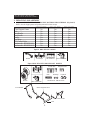
- Catégorie
- Chauffe-eau
- Taper
- User's Manual And Operating Instructions
Ce manuel convient également à

THERMOHEAT
CONSUMER : Retain this manual for future reference.
Questions, problems, missing parts? Before returning to your retailer, call our customer
service department at 877-447-4768 8:30 a.m. - 4:30 pm CST, Monday - Friday.
or email us at [email protected]
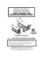
INDOOR/OUTDOOR PRODUCTS
KEROSENE PORTABLE
FORCED AIR HEATERS
“USER’S MANUAL AND
OPERATING INSTRUCTIONS”
Before the first use of this heater, please read this USER’S MANUAL very
carefully. This USER’S MANUAL has been designed to instruct you as to
the proper manner in which to assemble, maintain, store, and most
importantly, how to operate the heater in a safe and efficient manner.
Please keep this manual for future reference.
COMPLIES WITH UL733 AND
ANSI A10.10-1990
CAN/CSA/B140.0-03 AND CSA
B140.8-1967
MODEL : RMC-KFA75TL, RMC-KFA125TL, RMC-KFA210TL

1
NEVER LEAVE THE HEATER
UNATTENDED WHILE BURNING!
DANGER: IMPROPER USE OF THIS HEATER CAN RESULT IN SERIOUS INJURY OR DEATH
FROM BURNS, FIRE, EXPLOSION, ELECTRICAL SHOCK AND/OR CARBON
MONOXIDE POISONING.
WARNINGS:
1. RISK OF INDOOR AIR POLLUTION!
• Use this heater only in well ventilated areas. Provide at least a three-square foot (2,800 sq. cm.)
opening of fresh outside air for each 100,000 BTU/hr. of heater rating.
• People with breathing problems should consult a physician before using the heater.
• Carbon monoxide poisoning: Early signs of carbon monoxide poisoning resemble the flu, with headaches, dizziness
and/or nausea. If you have these signs, the heater may not be working properly.
Get fresh air at once! Have the heater serviced. Some people are more affected by carbon monoxide than others.
These include pregnant women, persons with heart or lung disease or anemia, those under the influence of alcohol, or
those at high altitudes.
• Never use this heater in living or sleeping areas.
2. RISK OFBURNS/FIRE/EXPLOSION!
• NEVERuse any fuel other than 1-K kerosene, #1 disel/fuel oil in this heater.
• NEVERuse fuel such as gasoline, benzene, paint thinners or other oil compounds in this heater.
(RISKOFFIREOREXPLOSION)
• NEVERuse this heater where flammable vapors may be present.
• NEVERrefill the heaters fuel tank while heater is operating or is still hot.
Minimum Clearances: Outlet: 8 feet (250cm) / Sides, top and rear: 4 feet (125cm)
• NEVERblock air inlet (rear) or air outlet (front) of heater.
• NEVERuse duct work in front or behind of heater.
• NEVERmove, handle, service a hot, operating or plugged in heater.
• NEVERtransport heater with fuel in it’s tank.
• When used with an optional thermostat or if equipped with a thermostat heater may start at any time.
• ALWAYSlocate heater on a stable a
nd level
surface.
• ALWAYSkeep children and animals away from heater.
• Bulk fuel storage should be a minimum of 25 ft. from heaters, torches, portable generators or other sources of ignition.
All fuel storage should be in accordance with federal, state or local authorities having jurisdiction.
3. RISK OF ELECTRIC SHOCK!
• Use only the electrical power (voltage and frequency) specified on the model plate of the heater.
• Use only a three-prong, grounded outlet and extension cord.
• ALWAYSinstall the heater so that it is not directly exposed to water spray, rain, dripping water or wind.
• ALWAYSunplug the heater when not in use.
PROPOSITION 65 WARNING: Fuels used in gas, wood-burning or oil fired appliances, and the
products of combustion of such fuels, contain chemicals known to the State of California to cause cancer,
birth defects and other reproductive harm.
MASSACHUSETTS RESIDENTS: Massachusetts state law prohibits the use of this heater in any
building which is used in whole or in part for human habitation. Use of this heating device in
Massachusetts requires local fire dept. permit (M.E.L.C. 148, Section 10A.)
CANADIAN RESIDENTS: Use of this heater shall be in accordance with authorities having
jurisdiction and CSA Standard B139.
NEW YORK CITY RESIDENTS:For use only at construction sites in accordance with applicable NYC
codes
under NYCFD certificate of approval # 5034 and 5037.
CAUTION :
Hot while in operation. Do not touch. Keep children,
clothing and combustibles away from heater.

2
NEVER LEAVE THE HEATER
UNATTENDED WHILE BURNING!
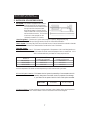
ITEM PAGE #
PRECAUTIONS - SAFETY GUIDE 1
1. INTRODUCTION 2
2. FEATURES 2
3. UNPACKING AND ASSEMBLY 4
4. KEROSENE (1-K OR NO. 1 FUEL OIL) 6
5. OVERVIEW OF HEATER DESIGN 7
6. FUELING YOUR HEATER 8
7. OPERATION 8
8. LONG TERM STORAGE OF YOUR HEATER 9
9. MAINTENANCE 10
10. REPLACING FUSE 14
11. TROUBLE SHOOTING GUIDE 15
12. WIRING DIAGRAM 16
13. SPECIFICATIONS 17
14. EXPLODED PARTS DRAWING 18
15. PARTS LIST 20
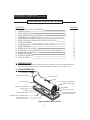
1. INTRODUCTION
Please read this USER’S MANUAL carefully. It will show you how to assemble, maintain, and operate the
heater safely and efficiently to obtain full benefits from its many built-in features.
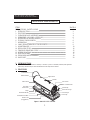
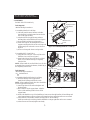
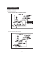
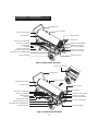
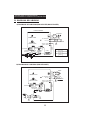
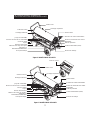
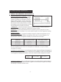
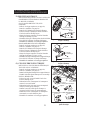
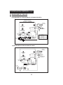
2. FEATURES
CONTENTS OF USER’S MANUAL
Fan Guard
BTU Control Knob
Cord Wrap
Pressure Gauge
Fuel Gauge
Fuel Cap
Front Guard
Hot Air Outlet
Lower Shell
Fuel Tank
Side Cover
Lamp
Thermostot Knob
Power/Reset Switch
Power Cord
(Piggy Back)
Upper Shell
Handle
Figure 1. RMC-KFA75TL MODEL

3
NEVER LEAVE THE HEATER
UNATTENDED WHILE BURNING!
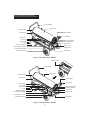
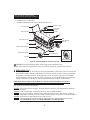
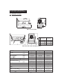
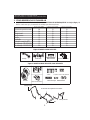
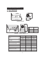
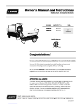
Figure 2. RMC-KFA125TL MODEL
Figure 3. RMC-KFA210TL MODEL
Hot Air Outlet
Shell Lower
Fuel Gauge
Fuel Cap
Side Cover
Lamp
Thermostot Knob
Room Temp. Display
Power/Reset Switch
Pneumatic Wheel
Hot Air Outlet
Shell Lower
Fuel Gauge
Fuel Cap
Side Cover
Lamp
Thermostot Knob
Room Temp. Display
Power/Reset Switch
Pneumatic Wheel
Front Handle
Upper Shell
Front Handle
Upper Shell
Electric Outlet
Rear Handle
Cord Wrap
BTU Control Konb
Pressure Gauge
Fan Guard
Power Cord
(Piggy Back)
Drain Plug
Rear Handle
Cord Wrap
BTU Control Konb
Pressure Gauge
Fan Guard
Power Cord
Drain Plug

4
NEVER LEAVE THE HEATER
UNATTENDED WHILE BURNING!
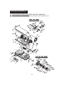
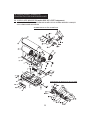
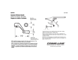
Figure 5. RMC-KFA125TL/ RMC-KFA210TL MODELS
Handle Cord Wraps
Hardware Kit
HW-KFA1001
BTU Control Valve
BTU Control Valve
Cord Wraps
Wheel Support Frame
Rear Handle
Axle
Front Handle
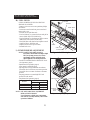
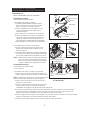
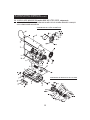
3. UNPACKING AND ASSEMBLY
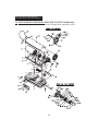
1. REMOVE THE HEATER AND ALL PACKING MATERIALS FROM THE BOX. (Fig. 4 and 5)
NOTE : Save the shipping carton and packing materials for future storage.
Figure 4. RMC-KFA75TL MODEL
RMC-KFA75TL RMC-KFA125TL
RMC-KFA210TL
Wheel Support Frame No Yes Yes
Axle No Yes Yes
Front Handle No Yes Yes
Rear Handle No Yes Yes
Handle Yes No No
Cord Wrap Yes Yes Yes
BTU Control Valve Yes Yes Yes
Hardware kit : HW-KFA1001 Yes No No
Hardware kit : HW-KFA1013 No Yes Yes
Wheels
Screws L&S Flange Screws
Nuts Bushings Cap Nuts
Hardware Kit : HW-KFA1013

5
NEVER LEAVE THE HEATER
UNATTENDED WHILE BURNING!
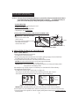
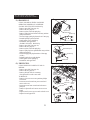
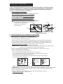
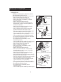
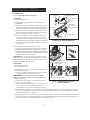
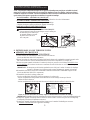
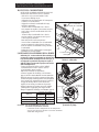
2. ASSEMBLY
For RMC-KFA75TL Model only
Tools Required
• Medium Phillips Screwdriver.
1. Assembling Handle & Cord Wrap
1) Lift front guard for arrow direction and make
sure that guard’s wedged portion fits into the slit
hole on the upper housing.
2) Align the holes in the upper housing with ttwo
mounting holes on the handle as shown in Figure 6.
3) Secure handel with Screws with provided.
4) Insert card wrap into the rectangle holes on the
supportor and align the hole on the cord wrap with
the mounting hole on the side cover as shown in
Figure 6.
5) Secure cord wrap with Screws with provided.
2. Assembling BTU Control Valve.
1) Align slit hole on body of Valve with Tab on the
End Filter Cover as shown in figure 7.
2) Insert hooked leg of valve fully into slot of End
Filter Cover so that hooked leg is completely
locked to Slot.
NOTE : When install valve to End Filter Cover, If valve
is assembled for incorrect knob direction, Hooked leg is
not completely locked to slot.
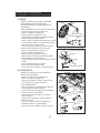
Tools Required
• Medium Phillips Screwdriver.
• 19
Socket Wrench
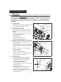
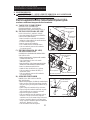
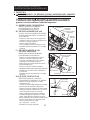
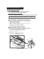
1. Assembling Handle & Wheel and Cord Wrap
1) Slide axle through wheel support frame.
Install wheel bushings and wheels on axle
NOTE : When installing wheels, tube valve should face
out from support frame (Figure 8.)
2) Attach Cap Nuts on axle ends and tighten with
Socket Wrench.
3) Place heater on wheel support frame. Align the
holes on fuel tank flange with holes on wheel
support frame.
4) Position the Handles on top of fuel tank flange. Insert screws through handles, fuel tank flange and
wheel support frames as shown in Figure 8 and attach nut finger tight after each screw is inserted.
5) Align the hole on the handles with the mounging hole on the Cord Wrap.
Insert Screws through Cord Wrap, handles and attach nut finger tight after each screw is inserted.
6) After all screws are inserted, tighten nuts firmly.
Figure 6. Assembling Handle & Cord Wrap
Figure 7. Assembling BTU Control Valve
Handle
Screw
Frong Guard
Slit Hole
Cord Wrap
Screw
correct
Incorrect
BTU Control Valve
End Filter Cover
Tab
Slit Hole
Slot
Hooked Leg
Side Cover
Suppotor
Knob direction when install
valve to End Filter Cover.
Wedged Portion

2. Assembling BTU Control Valve.
Assemble by method previous page for model RMC-KFA75TL.
6
NEVER LEAVE THE HEATER
UNATTENDED WHILE BURNING!
4. KEROSENE (1-K)
For optimal performance of this heater, it is strongly suggested that 1-K kerosene be used. 1-K kerosene has
been refined to virtually eliminate contaminants, such as sulpher. Which can cause a rotten egg odor during
the operation of the heater. However, #1 diesel/fuel oil may also be used if 1-K kerosene is not available.
Be advised that these fuels do not burn as clean as 1-K kerosene, and care should be taken to provide more
fresh air ventilation to accomodate any added contaminants that may be added to the heated space.
KEROSENE SHOULD ONLY BE STORED IN A BLUE CONTAINER THAT IS CLEARLY
MARKED “KEROSENE”. NEVER STORE KEROSENE IN A RED CONTAINER.
Red containers are associated with gasoline.
NEVER store kerosene in the living space. Kerosene should be stored in a well ventilated place outside the
living area.
NEVER use any fuel other than 1-K kerosene (#1 fuel oil is an acceptable substitute.)
NEVER use fuel such as gasoline, benzene, alcohol, white gas, camp stove fuel, paint thinners, or other oil
compounds in this heater. These are volatile fuels that can cause an explosion or uncontrolled flames.
NEVER store kerosene in direct sunlight or near a source of heat.
NEVER use kerosene that has been stored from one season to the next. Kerosene deteriorates over time.
“OLD KEROSENE” WILL NOT BURN PROPERLY IN THIS HEATER.
Figure 8. Assembling Handle & Wheel and Cord wrap
CAUTION : DO NOT OPERATE heater without support frame assembled to tank.
NOTE : Heater should be inspected before each use, and at least annually by a qualitied service person.
Front Handle
Hot Air Outlet
Fuel Tank Flange
Nut
Wheel Support Frame
Wheel(Pneumatic)
Cap Nut
Nut
Rear Handle
Air Inlet
Axle
Wheel Bushing
Flange Screw
Cord Wrap
Screw-S
Screw-L
Wheel Tube Valve

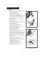
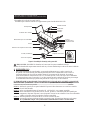
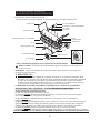
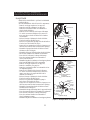
5. OVERVIEW OF HEATERS DESIGN
Fuel System : This heater is equipped with an electric
air pump that forces air through the air
line connected to the fuel intake and then
through a nozzle in the burner head.
When the air passes in front of the fuel
intake it causes fuel to rise from the tank
and into the burner nozzle. This fuel and
air mixture is then sprayed into the
combustion chamber in a fine mist.
“Sure Fire Ignition” :
The electronic ignitor sends voltage to a specially designed spark plug.
The spark plug ignites the fuel and air mixture described above.
The Air System :
The heavy duty motor turns a fan that forces air into and around the combustion chamber.
Here the air is heated and then forced out the front of the heater.
The Safety System :
A. Temperature Limit Control : This heater is equipped with a Temperature Limit Control designed to turn
off the heater should the internal temperature rise to an unsafe level. If this
device activates and turns your heater off it may require service.
Once the temperature falls below the reset temperature you will be able to start your heater.
B. Electrical System Protection : This heaters electrical system is protected by a fuse mounted to the PCB
assembly that protects it and other electrical components from damage.
If your heater fails to operate check this fuse first and replace as needed.
C. Flame-Out Sensor : Utilizes a photocell to monitor the flame in burn chamber during normal operation.
It will cause the heater to shut-off should the burner flame extinguish.
7
NEVER LEAVE THE HEATER
UNATTENDED WHILE BURNING!
Internal Shut-Off Temp. Reset Temperature
MODELS
Plus/Minus 10 Degrees Plus/Minus 10 Degrees
RMC-KFA75TL
176˚F/80˚C 122˚F/50˚C
RMC-KFA125TL
230˚F/110˚C 194˚F/90˚C
RMC-KFA210TL
194˚F/90˚C 140˚F/60˚C
FUSE TYPE: All Models 125 volt / 8 amps

6. FUELING YOUR HEATER
NEVER FILL THE HEATER FUEL TANK IN THE LIVING SPACE : FILL THE TANK OUTDOORS.
DO NOT OVERFILL YOUR HEATER AND BE SURE HEATER IS LEVELED.
IMPORTANT NOTICE REGARDING FIRST IGNITION OF HEATER :
The first time you light the heater, it should be done outdoors. This allows the oils, etc. used in
manufacturing the heater to burn off outside.
WARNING!! : NEVER REFILL HEATER FUEL TANK WHEN HEATER IS OPERATING OR STILL HOT.
7. OPERATION
A.) VENTILATION
RISK OF INDOOR AIR POLLUTION/USE HEATER ONLY IN WELL VENTILATED AREAS.
Provide a fresh air opening of at least three square feet (2,800 sq. cm) for each 100,000 BTU/Hr.
rating. Provide extra fresh air if more heaters are being used.
Example : A RMC-KFA210TL heater requires one of the following:
• a two-car garage door raised six inches (15.24 cm)
• a single-car garage door raised nine inches (22.86 cm)
• two, thirty-inch (76.20 cm) windows raised fifteen inches (38.1 cm)
B.) OPERATION
TO START HEATER
1. Fill fuel tank with kerosene or No. 1 fuel oil.
2. Attach fuel cap.
3. Plug power cord of heater into three-prong, grounded extension cord. Extension cord must be at
least six feet long.
Extension Cord Wire Size Requirements
• 6 to 10 feet (1.8 to 3 meters) long, use 18 AWG conductor.
• 11 to 100 feet (3.4 to 30.5 meters) long, use 16 AWG conductor.
• 101 to 200 feet (30.8 to 61 meters) long, use 14 AWG conductor.
4. Turn “THERMOSTAT CONTROL Knob” to desired setting (setting range : 40˚F ~ 110˚F)
and Turn “BTU control Knob” to desired level “High or LOW” (See Figure 9.)
5. Push Power Switch to “ON” position, Power lndicator Lamp will light and heater will start.
NOTE : Room Temp. display indicates as following (RMC-KFA125TL/210TL Models only)
• when room temp. is less than 0 ; “L”
• when room temp. is between 0 and 99 ; Indicates in figure.
• when room temp. is more than 99
; “Hi”
If heater does not start, the thermostat setting may be too low, turn “thermostat Control Knob” to
higher position to start heater. If heater still does not start, turn power switch to “OFF” and then to
“ON” position. If heater still does not start, see Troubleshootiong Guide on page15.
NOTE : User can change BTU LEVEL “High or Low” while in operation by turnig BTU Control Knob.
If heater is operated by HIGH BTU LEVEL, Turn BTU Control Knob 90
to clockwise.
If heater is operated by LOW BTU LEVEL, Turn BTU Control Knob 90 to counter clockwise.
8
NEVER LEAVE THE HEATER
UNATTENDED WHILE BURNING!
Figure 9. Controls for All Models
Power/Reset
Switch
RMC-KFA75TL Model
RMC-KFA125TL/210TL Model
Room Temp. Display
Power/Reset
Switch
Thermostat
Control Knob
Thermostat
Control Knob
Lamp
Lamp
Fan Guard
BTU Control Knob
BTU
Control Knob

9
NEVER LEAVE THE HEATER
UNATTENDED WHILE BURNING!
NOTICE : The major electrical components of this heater are protected by a safety fuse mounted to the PCB board.
If your heater fails to start, check this fuse first and replace as necessary. You should also check your
power source to insure that proper voltage and frequency are being supplied to the heater.
TO STOP
HEATER
1. Turn switch to “OFF” and unplug power cord.
TO RESTART
HEATER
1.Wait 10 seconds after stopping heater.
2. Repeat steps under to start heater.
EXTRA ELECTRIC OUTLET & PIGGYBACK POWER CORD
WARNING : SHOCK HAZARD!
8. LONG TERM ST
ORAGE OF YOUR HEATER
FUEL TANK DRAIN
1. Drain fuel tank through fuel cap opening.
(For RMC-KFA75TL Model Only)
2. Remove drain plug from rear bottom side of fuel tank by pulling plug grip downward and drain.
(For RMC-KFA125TL/210TL Models Only. See Figure 11)
3. Using a small amount of kerosene, swirl and rinse the inside of the tank.
NEVER mix water with the kerosene as it will cause rust inside the tank.
Pour the kerosene out making sure that you remove it all.
IMPORTANT : Do not store kerosene over summer months for use during next heating season.
Using old fuel could damage heater.
4. Reinstall fuel cap. Properly dispose of old and dirty fuel. (For RMC-KFA75TL Model Only)
5. Reinstall Drain Plug as follows.
(For RMC-KFA125TL/210TL Models Only. See Figure 12)
- Insert plug’s seal head fully into drain hole so that flange is flush to tank’s bottom.
- Insert seal cap fully into head hole so that cap flange is flush to head flange.
IMPORTANT : Reinstall plug fully into hole in tank, Otherwise it will not seal completely.
6. Store heater in dry well ventilated area. Make sure storage place is free of dust and corrosive fumes.
7. Store the heater in the original box with the original packing material and keep the USER’S
MANUAL
with the heater.
• Always cover electric outlet
when not in use.
• Don’t plug and use a appliance
more than 120V/60Hz 5A
current in this outlet
Figure 11. Drain Plug Removal Figure 12. Drain Plug Reinstall
Drain Plug
Plug Grip
Drain Hole
Seal Head
Head Hole
Seal Cap
Cap Flange
Head Flange
Cover Cover
Outlet
Fuel Tank
Head Flange
Rear bottom side
of Fuel Tank
RMC-KFA210TL Model only RMC-KFA75TL/125TL Models only
Figure 10. Electric Outlet
Outlet

A.) FUEL TANK
FLUSH EVERY 200 HOURS OF OPERATION OR
AS NEEDED (SEE STORAGE, PAGE 9)
B.) AIR INTAKE FILTER
WASH AND DRY WITH SOAP AND WATER
EVERY 500 HOURS OF OPERATION OR AS
NEEDED.
- Remove screws along each side of heater using
medium phillips screwdriver.
- Lift upper shell off.
- Remove fan guard.
- Wash or replace air intake filter.
- Reinstall fan guard and upper shell.
C.) AIR OUTPUT FILTER, LINT FILTER
REPLACE EVERY 500 HOURS OF OPERATION
OR ONCE A YEAR.
- Remove upper shell and fan guard (See Air Intake Filter).
- Trun Air pressure gauge counter-clock wise and
remove.
- Remove end filter cover screws using medium
phillips screwdriver.
- Remove end filter cover.
- Replace air output and lint filter.
- Reinstall end filter cover and air pressure gauge.
- Reinstall fan guard and upper shell.
D.) FAN BLADES
CLEAN EVERY SEASON OR AS NEEDED.
- Remove upper shell (See Air Intake Filter).
- Use M6 allen wrench to loosen set screw
which holds fan blade to motor shaft.
- Slip fan blade off motor shaft.
- Clean fan blade using a soft cloth moistened with
kerosene or solvent.
- Dry fan blade thoroughly.
- Reinstall fan blade on motor shaft. Place fan
blade hub flush with end of motor shaft.
- Place set screw on flat of shaft. Tighten set screw
firmly (40-50 inch-pounds/4.5-5.6 N-m).
- Reinstall upper shell.
10
NEVER LEAVE THE HEATER
UNATTENDED WHILE BURNING!
9. MAINTENANCE
WARNING!! : NEVER SERVICE HEATER WHILE IT IS PLUGGED IN OR
WHILE HOT!
USE ORIGINAL EQUIPMENT REPLACEMENT PARTS. Use of third party or
other alternate components will void warranty and may cause unsafe operating
conditions.
Figure 13 Air Intake Filter Access
Figure 14 Air Outprt Filter Access
Figure 15 Fan Assembly
Upper Shell
Screw
Screw
Fan Guard
Air Intake Filter
Flush
Motor
Blade
Fan
Lint Filter
Pressure Gauge
Air Intake Filter
Air Output Filter
End filter cover
Set screw
Motor Shaft

11
NEVER LEAVE THE HEATER
UNATTENDED WHILE BURNING!
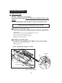
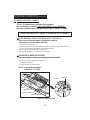
E.) NOZZLE
REMOVE DIRT IN NOZZLE AS NEEDED (SEE PAGE 16).
(For RMC-KFA75TL/125TL Models Only)
- Remove upper shell (See page 10).
- Remove fan blade (See page 10).
- Remove fuel and air line hoses from burner head.
- Remove ignitor wire from spark plug.
- Remove three screws using medium phillips screwdriver
and remove burner head from combustion chamber.
- Remove spark plug from burner head using medium
phillips screwdriver.
- Carefully remove nozzle from burner head using 5/8”
socket wrench.
- Blow compressed air through face of nozzle. (this will
remove any dirty in nozzle)
- Reinstall nozzle into burner head and tighten firmly.
(80~110 inch-pounds)
- Reinstall spark plug in burner head.
- Attach burner head to combustion chamber.
- Attach ignitor wire to spark plug.
- Attach fuel and air line hoses to burner head.
- Reinstall fan blade and upper shell.
(For RMC-KFA210TL Model Only)
- Remove upper shell (See page 10).
- Remove fan (See page 10).
- Remove fuel and air line hoses from adaptor-nozzle.
- Remove ignitor wire from spark plug.
- Remove four screws using medium phillips screwdriver
and remove burner-bracket from combustion chamber.
- Remove spark plug from burner head using medium
phillips screwdriver.
- Carefully remove nozzle from adaptor-nozzle using 5/8”
socket wrench.
- Blow compressed air through face of nozzle.
(this will remove any dirt in nozzle)
- Reinstall nozzle into adaptor-nozzle and tighten firmly.
(80~110 inch-pounds)
- Reinstall spark plug in spark-bracket.
- Attach burner-bracket to combustion cahmber.
- Attach ignitor wire to spark plug.
- Attach fuel and air line hoses to adaptor-nozzle.
- Reinstall fan blade and upper shell.
Combusion chamber
Burner Bracket
Screw
Ignitor Wire
Fuel Line Hose
Bracket Burner
Bracket Spark
Fuel Line
Fitting
Spark Plug
Air Line Fitting
Air Line Hose
Nozzle Face
Nozzle
Spark Plug
Figure 17. Nozzle Replacement
Figure 16. Nozzle Replacement
Fuel Line
Air Line
Burner Head
Nozzle
Nozzle Face
Ignitor Wire
Spark Plug
Burner Head
Screw
Combustion Chamber

12
NEVER LEAVE THE HEATER
UNATTENDED WHILE BURNING!
F.) SPARK PLUG
CLEAN AND REGAP EVERY 600 HOURS
OPERATION OR REPLACE AS NEEDED.
(For RMC-KFA75TL/125TL Models Only)
- Remove upper shell (See page 10).
- Remove fan (See page 10).
- Remove ignitor wire from spark plug.
- Remove spark plug from burner head using medium
phillips screwdriver.
- Clean and regap spark plug electrodes to 3.5mm gap.
- Reinstall spark plug in burner head.
- Attach ignitor wire to spark plug.
- Reinstall fan and upper shell.
(For RMC-KFA210TL Model Only)
- Remove upper shell (See page 10).
- Remove fan (See page 10).
- Remove ignitor wire from spark plug.
- Remove spark plug from spark-bracket using medium
phillips screwdriver.
- Clean and regap spark plug electrodes to 3.5mm gap.
(0.138 )
- ReInstall spark plug in spark-bracket.
- Attach ignitor wire to spark plug.
- Reinstall fan and upper shell.
G.) PHOTOCELL
CLEAN PHOTOCELL ANNUALLY OR AS
NEEDED.
- Remove upper shell (See page 10).
- Remove fan (See page 10).
- Remove photocell from it’s mounting.
Clean photocell lens with cotton swab.
TO REPLACE:
- Remove side cover screws using medium phillips
screwdriver.
- Disconnect switch wires from power switch and
remove side cover.
- Disconnect wires from circuit board and remove
photocell.
- Install new photocell and connect wires to circuit
board.
- Replace switch wires to power switch and side cover.
- Replace fan and upper shell.
Switch
Wires
Brocket
Photocell
Lens
Incorrect Correct
Photocell
Wire
Power
Switch
Screw
Side Cover
Bracket Burner
Burner Head
Spark Plug
GAP
Spark Plug
Ignitor wire
Figure 18. Spark Plug Regap
Figure 19. Spark Plug Regap
Ignitor Wire
Bracket Spark
Spark Plug
Figure 20. Photocell Replacement

H.) FUEL FILTER
CLEAN OR REPLACE TWICE A HEATING
SEASON OR AS NEED.
- Remove side cover screws using medium phillips
screwdriver.
- Disconnect switch wires from power switch and
remove side cover.
- Pull fuel line off fuel filter neck.
- Turn fuel filter 90˚ to counter clockwise and pull to
remove (RMC-KFA75TL Model only).
- Turn fuel filter 90˚ to clockwise and pull to remove
(RMC-KFA125TL/210TL Models only).
- Wash fuel filter with clean fuel and replace in tank.
- Attach fuel line to fuel filter neck.
- Replace switch wires to power switch.
- Reinstall side cover.
I.) PUMP PRESSURE ADJUSTMENT
NOTE: Low BTU level pump pressure is
increased or decreased according to High
BTU level pump pressure, So, In case
need Pump pressure adjusting, Only
adjust high BTU level Pump Pressure.
- Turn BTU CONTROL Knob to HIGH BTU Level.
(See Operation, page 8)
- Start heater (See Operation, page 8)
Allow motor to reach full speed
- Adjust pressure (Using a flat blade screwdriver)
Turn relief valve to clockwise to increase pressure.
Turn relief valve to counter clockwise to decrease
pressure.
- Set pump pressure to correct High BTU level
pressure for each model
- Stop heater (See Operation, page 8)
NOTE : USE ONLY ORIGINAL EQUIPMENT
REPLACEMENT PARTS.
Use of alternate or third party components
will void any warranty and may cause unsafe
operation condition.
Pump Pressure
High BTU level Low BTU level
RMC-KFA75TL 3.8 psi 2.7 psi
RMC-KFA125TL 5.5 psi 3.5 psi
RMC-KFA210TL 8.5 psi 6.5 psi
Pressure Gauge
Relief Valve
Fuel Filter
Fuel line
Switch Wires
Screw
Side Cover
Power Switch
Flat blade
Screw
driver
13
NEVER LEAVE THE HEATER
UNATTENDED WHILE BURNING!
Figure 21. Fuel Filter ReplacementFigure 21. Fuel Filter Replacement
Figure 22. Adjusting Pump Pressure
MODEL

14
NEVER LEAVE THE HEATER
UNATTENDED WHILE BURNING!
10. REPLACING FUSE
NOTICE : This heater is fuse protected.
If your heater fails to ignite, DO NOT RETURN YOUR HEATER TO THE
STORE.
Please follow the simple instruction below to inspect and change the fuse.
WARNING : SHOCK HAZARD
To prevent personal injury, unplug the power cord before replacing fuse.
1. Unplug heater.
2. Remove side cover screws using medium phillips screw driver.
3. Disconnect switch wires from power switch.
4. Remove fuse from fuse holder.(See Figure 23.)
5. Replace fuse with enclosed fuse.
WARNING : FIRE HAZARD
To avoid fire, Do not substitute with a higher or lower current rating.
6. Replace switch wires to power switch.
7. Replace side cover.
NOTE : Specified fuse rating : AC 125/8A
PROCEDURE FOR REPLACING FUSE
Screw
Side Cover
Power Switch
Switch Wire
Fuse
Fuse Holder
Figure 23. Replacing Fuse

15
NEVER LEAVE THE HEATER
UNATTENDED WHILE BURNING!
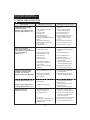
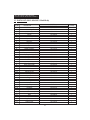
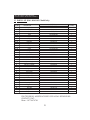
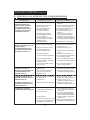
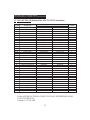
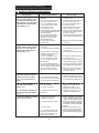
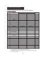
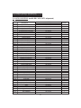
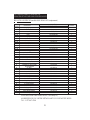
11. TROUBLE SHOOTING GUIDE
2. See Air Output,Air intake2. Dirty Air Output,Air Intake
a short period of time.
Heater will not turn-on
room temp. display indicates "E3")
(Indicator Lamp is flickering and
room temp. display indicates "E2")
(Indicator Lamp is flickering and
(Indicator Lamp is on or flickering)
was in the " ON " Position.
is plugged in and power switch
Fan does not turn when heater
indicates " E1 ")
and room temp.display
of time.(Indicator Lamp is flickering
motor runs for a short period
Heater will not ignite but
room temp. display indicates " E1 ")
(Indicator Lamp is flickering and
(Indicator Lamp is off)
temperature limit safety device
and PCB board.
4. Bad electrical connection between
1. Room Temp. sensor disconnected.
3. Blown fuse.
2. No electrical power
device is overheated.
1. Temperature limit safety
1. Thermostat switch failure.
2. Sensor Failure.
See Wiring Diagram, Page 16.
4. Check electrical connections
3. Replace safety fuse in PCB board.
Check power supply.
extension cord are plugged in.
2. Check to insure heater cord and
and allow to cool(about 10 min.)
1. Turn power switch to "OFF"
See Wiring diagram, Page 16.
1. Replace switch.
See Wiring diagram, Page 16.
2. Replace sensor.
See Wiring diagram, Page 16.
1. Reconnect sensor.
8. Ignitor wire is not attached to
PCB assembly.
between motor and MAIN
2. Bad electrical connection
1. Thermostat setting is too low.
spark plug.
PCB assembly.
between ignitor and MAIN
7. Bad electrical connection
6. Water in fuel tank.
5. Dirt in Nozzle.
4. Dirty fuel filter.
plug and/or improper gap.
3. Carbon deposits on spark
2. Wrong pump pressure.
1. No fuel in tank.
8. Defective Photocell.
PCB assembly.
between photocell and MAIN
7. Bad electrical connection
Properly installed.(Not seeing the
flame)
6. Photocell Assembly not
5. Dirty Photocell Lens.
4. Dirt in Nozzle.
3. Dirty Fuel Filter.
or Lint Filter.
See Wiring Diagram, Page 16.
2. Check electrical connections,
to a higher setting.
1. Turn thermostat control knob
plug. See Spark Plug, Page 12.
8. Attach ignitor wire to spark
See wiring diagram, Page 16.
7. Check electrical components
kerosene, Page 9.
6. Flush fuel tank with clean
5. See Nozzle,Page 11.
4. See Fuel Filter,Page 13.
3. See Spark Plug,Page 12.
Page 13.
2. See Pump Pressure Adjustment,
1. Fill tank with kerosene.
8. Replace Photocell, Page 12.
See wiring diagram, Page 16.
7. Check electrical components
Page 12.
properly seated in bracket,
6. Make sure photocell boot is
5. Clean Photocell Lens, Page 12.
4. See Nozzle, Page 11.
3. See Fuel Filter, Page 13.
and Lint Filters, page 10.
assembly shuts heater off after
Heater ignites but MAIN PCB
TROUBLE POSSIBLE CAUSE
1. Wrong pump pressure
Page 13.
1. See Pump Pressure Adjustment,
CORRECTIVE ACTION

16
NEVER LEAVE THE HEATER
UNATTENDED WHILE BURNING!
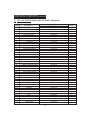
12. WIRING DIAGRAM
A) WIRING DIAGRAM (RMC-KFA75TL/RMC-KFA125TL)
MODEL CAPACITOR
1/G WIRE
COLOR
75TL 12uF/230VAC
BLACK
RED
125TL 30uF/250VAC
BLACK
WHITE
B) WIRING DIAGRAM (RMC-KFA210TL)

17
NEVER LEAVE THE HEATER
UNATTENDED WHILE BURNING!
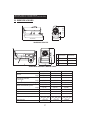
RMC-KFA75TL Model
RMC-KFA125TL / RMC-KFA210TL Models
43.5"(1105 )
24.6"(625
)
26.6"(675 )
KFA125TL
KFA210TL
37.5"(953 )
25.0"(633
)
23.0"(584
)
D
W
H
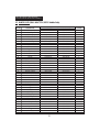
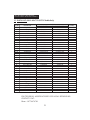
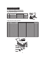
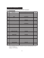
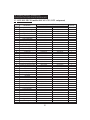
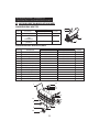
MODEL RMC-KFA75TL RMC-KFA125TL RMC-KFA210TL
HIGH 75,000 125,000 210,000
LOW 55,000 100,000 170,000
HIGH 0.57(2.16) 0.95(3.60) 1.6(6.10)
LOW 0.42(1.59) 0.76(2.88) 1.3(4.92)
Fuel Tank Capacity - Gal.
(
./Hr)
5(18.9) 10(37.9) 13(49.2)
HIGH 3.8(0.27) 5.5(0.39) 8.5(0.60)
LOW 2.7(0.19) 3.5(0.25) 6.5(0.46)
Volt/Hz 120Vac/60Hz 120Vac/60Hz 120Vac/60Hz
Amps. 1.6 2.5 3.7
Phase 1 1 1
32.0
11.7 16.7 37.5 23.0 25.0 43.5 24.6 26.6
813 297 424) 953 584 633) 1105 625 675)
Weight Lbs.(
) 26.5(12.0) 52.0(23.5) 62.0(28.0)
13. SPECIFICATIONS
Fuel Consumption
- Gal./Hr(
./Hr)
Pump Pressure PSI(kgf/
)
BTU/Hr.
Size(D W H), Inch( )

NEVER LEAVE THE HEATER
UNATTENDED WHILE BURNING!
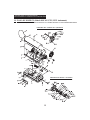
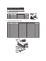
14. EXPLODED PARTS DRAWING (RMC-KFA75TL/125TL Models Only)
NOTE : SPECIFY MODEL NUMBER AND PART NUMBER WHEN ORDERING PARTS.
18

19
NEVER LEAVE THE HEATER
UNATTENDED WHILE BURNING!
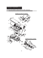
14. EXPLODED PARTS DRAWING (RMC-KFA 210TL Model Only)
NOTE : SPECIFY MODEL NUMBER AND PART NUMBER WHEN ORDERING PARTS.
La page est en cours de chargement...
La page est en cours de chargement...
La page est en cours de chargement...
La page est en cours de chargement...
La page est en cours de chargement...
La page est en cours de chargement...
La page est en cours de chargement...
La page est en cours de chargement...
La page est en cours de chargement...
La page est en cours de chargement...
La page est en cours de chargement...
La page est en cours de chargement...
La page est en cours de chargement...
La page est en cours de chargement...
La page est en cours de chargement...
La page est en cours de chargement...
La page est en cours de chargement...
La page est en cours de chargement...
La page est en cours de chargement...
La page est en cours de chargement...
La page est en cours de chargement...
La page est en cours de chargement...
La page est en cours de chargement...
La page est en cours de chargement...
La page est en cours de chargement...
La page est en cours de chargement...
La page est en cours de chargement...
La page est en cours de chargement...
La page est en cours de chargement...
La page est en cours de chargement...
La page est en cours de chargement...
La page est en cours de chargement...
La page est en cours de chargement...
La page est en cours de chargement...
La page est en cours de chargement...
La page est en cours de chargement...
La page est en cours de chargement...
La page est en cours de chargement...
La page est en cours de chargement...
La page est en cours de chargement...
La page est en cours de chargement...
La page est en cours de chargement...
La page est en cours de chargement...
La page est en cours de chargement...
La page est en cours de chargement...
La page est en cours de chargement...
La page est en cours de chargement...
La page est en cours de chargement...
La page est en cours de chargement...
La page est en cours de chargement...
La page est en cours de chargement...
La page est en cours de chargement...
La page est en cours de chargement...
La page est en cours de chargement...
La page est en cours de chargement...
La page est en cours de chargement...
-
 1
1
-
 2
2
-
 3
3
-
 4
4
-
 5
5
-
 6
6
-
 7
7
-
 8
8
-
 9
9
-
 10
10
-
 11
11
-
 12
12
-
 13
13
-
 14
14
-
 15
15
-
 16
16
-
 17
17
-
 18
18
-
 19
19
-
 20
20
-
 21
21
-
 22
22
-
 23
23
-
 24
24
-
 25
25
-
 26
26
-
 27
27
-
 28
28
-
 29
29
-
 30
30
-
 31
31
-
 32
32
-
 33
33
-
 34
34
-
 35
35
-
 36
36
-
 37
37
-
 38
38
-
 39
39
-
 40
40
-
 41
41
-
 42
42
-
 43
43
-
 44
44
-
 45
45
-
 46
46
-
 47
47
-
 48
48
-
 49
49
-
 50
50
-
 51
51
-
 52
52
-
 53
53
-
 54
54
-
 55
55
-
 56
56
-
 57
57
-
 58
58
-
 59
59
-
 60
60
-
 61
61
-
 62
62
-
 63
63
-
 64
64
-
 65
65
-
 66
66
-
 67
67
-
 68
68
-
 69
69
-
 70
70
-
 71
71
-
 72
72
-
 73
73
-
 74
74
-
 75
75
-
 76
76


Thermoheat RMC-KFA75TL User's Manual And Operating Instructions
- Catégorie
- Chauffe-eau
- Taper
- User's Manual And Operating Instructions
- Ce manuel convient également à
dans d''autres langues
- español: Thermoheat RMC-KFA75TL
Autres documents
-
Dyna-Glo Delux KFA650DGD Mode d'emploi
-
-
-
BAZZ PR3311WH Guide d'installation
-
 L.B. White CP170AK Owner's Manual And Instructions
-
Desa 50 Manuel utilisateur
-
Master B 35 B 65 B 100 B 150 CEL Le manuel du propriétaire
-
 L.B. White CP400AK Owner's Manual And Instructions
-
 Prime-Line H 3712 Mode d'emploi
-


