
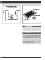
INDUCTION
COOKTOP
SERIES 700
INSTALLATION INSTRUCTIONS
INSTRUCTIONS D’INSTALLATION
INSTRUCCIONES PARA LA INSTALACIÓN


Dear Customer,
Thank you for purchasing a Fulgor Milano product. Fulgor Milano is committed to
excellence and our signature technologies provide you with professional tools for
your kitchen. One of our central philosophies is continuous investment in research that
is rooted in developing life enhancing technology. Our goal is to deliver products
that are worthy of your family recipes and that will breathe life into your kitchen, the
heart of your home. We invite you to enjoy your new Fulgor Milano product with
same amount of care and attention that we have put into creating it.
Your Life | Our Passion


EN
1
TABLE OF CONTENTS
PAGE
1 - Special Warnings 2
Before Starting Installation 2
2 - Product Dimensions and Cutout
Requirements 3
Important Preparation Suggestions 5
3 - Cooktop Installation 6
4 - Cooktop Installation Over a Single
Oven 9
5 - Electrical Connections 10
General information 10
3-Wire branch circuit 11
4--Wire branch circuit 11
IMPORTANT: Save these instructions for the local electrical
inspector use.
INSTALLER: Please leave this manual with owner for future
reference.
OWNER: Please keep this manual for future reference.
Pay attention to these symbols present in this
manual:
DANGER
You can be killed or seriously injured if you don’t
IMMEDIATELY follow instructions.
WARNING
This is the safety alert symbol. This symbol alerts you to
potential hazards that can kill or hurt you and others.
You can be killed or seriously injured if you don’t follow these
instructions.
WARNING
If the information in this manual is not followed
exactly, a fire or explosion may result in personal injury or death.
Do not store or use gasoline or other flammable vapors and
liquids in the vicinity of this or any other appliance.

EN
2
1 - Special Warnings
Proper installation is your responsibility.
Have a qualified technician install this cooktop.
IMPORTANT
- Observe all governing codes and ordinances.
- Write down the model and serial numbers before installing
the cook top. Both numbers are on the serial rating plate
located on bottom of cooktop housing.
Before Starting Installation
WARNING
It is the customer’s responsibility to contact a qualified
electrical installer to ensure that the electrical installation is
adequate and in conformity with national electrical code:
ANSI/NFPA 70-latest edition** or CSA standards C22.1-
94, Canadian Electrical Code, part No.0-M91 - latest
edition*** and all local codes and ordinances.
Copies of the standards listed may be obtained from:
** National Fire Protection Association One Batterymarch Park
Quincy, Massachusetts 02269
*** CSA International 8501 East Pleasant Valley Rd. Cleveland,
OH 44131-5575
To eliminate the risk of burns by reaching over heated surface
units, cabinet storage space located above the surface units
should be avoided. If cabinet storage is to be provided, the
risk can be reduced by installing a range hood that projects
horizontally a minimum of 5” (12,7 cm) beyond the outer edge
of the cabinet.
IMPORTANT INSTRUCTION
Please read all instructions before using this appliance.

EN
3
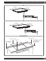
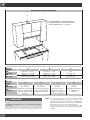
2 - Product Dimensions and Cutout Requirements
30”
30” 3/8
(771 mm)
21” 3/16
(538 mm)
1/4”
(6mm)
2” 5/8
(66 mm)
1” 1/16
(27 mm)
36”
36” 3/16
(919 mm)
21” 3/16
(538 mm)
1/4”
(6mm)
2” 5/8
(66 mm)
1” 1/16
(27 mm)
CUTOUT DIMENSION
LENGTH OF CUT
A
LENGTH OF CUT
B
1-1/2” (3.8CM)
MIN CLEARANCE
SEE NOTE
R
FROM EDGE OF CUTOUT
TO FRONT EDGE OF
COUNTERTOP
2-1/2” (6.5 cm)

EN
4
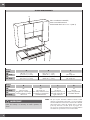
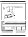
CUTOUT REQUIREMENTS
D
G
C
E
F
WALL COVERING CABINETS,
AND COUNTERTOP MUST
WITHSTAND HEAT UP TO 93° C (200° F)
Cutout
width A B C
30”
(76.2cm) 28-3/4” +/- 1/16”
(73.0 cm +/- 0.1cm)
19-7/16” +/- 1/16”
(49.4 cm +/- 1mm)
30”
(76.2 cm) min
36”
(91.4cm) 34-5/8” +/- 1/16”
(87.9 cm +/- 0.1cm)
19-7/16” +/- 1/16”
(49.4 cm +/- 1mm)
36”
(91.4 cm) min
Cutout
width D E F G
30”
(76.2cm) 18”
(45.7 cm) min
Height from countertop to
nearest cabinet on either
side of unit
30”
(76.2 cm) min.
(see note*) Clearance from
countertop to unprotected
overhead surface
2”
(5 cm) min
Clearance from cutout to
side wall on the left and
right of the unit
13”
(33 cm)
Depth of unprotected
overhead cabinets
36”
(91.4cm)
IMPORTANT
Under the cooktop it is necessary to install a partition, as
shown
NOTE: 24” (61 cm) min. clearance if bottom of wood or metal
cabinets is protected by not less than 1/4” (0.6 cm) flame
retardant millboard covered with no less than No. 28 MSG
sheet steel 0.015” (0.04 cm) stainless steel, or 0.024”
(0.06 cm) aluminum or 0.020” (0.05 cm) copper. 30”
(76.2 cm) min. clearance between top of cooking platform
and bottom of unprotected wood or metal cabinet.

EN
5
Important Preparation Suggestions
1. Chamfer all exposed edges of decorative laminate to
prevent damage from chipping.
2. Radius corners of cutout and file to ensure smooth edges
and prevent corner cracking. Recommend 1/4” or 3/8”
diameter drill to start cut at each corner.
3. Rough edges, inside corners which have not been rounded
and forced fits can contribute to cracking of the countertop
laminate.
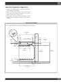
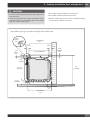
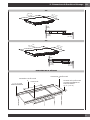
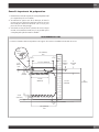
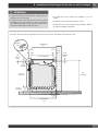
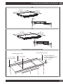
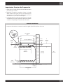
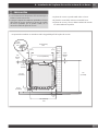
VERTICAL CLEARANCES
* The ventilation opening is to extend the full length of the cooktop cutout.
25” (635mm)
min
19 7/16” (494mm)
2 1/2”
(64mm)
3 ”
(76mm)
2 1/2”
(65mm)
1 5/8”
(40mm)
max
1/4”
(6mm)
min
4”
(101mm)
min
4 3/4”
(120 mm)
36”
(915mm)
27 3/4”
(705mm)
1 1/2”
(38 mm)
min
24” (610mm)
min
15 3/4”
(400mm)
5”
(127mm)
min
*1/4”
(6mm)
min

EN
6
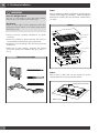
3 - Cooktop Installation
WARNING
Excessive Weight Hazard
Use two or more people to move and install cooktop.
Failure to do so can result in back or other injury.
Cut Hazard
Beware of sharp edges. Use the polystyrene ends when
carrying the product. Failure to use caution could result in
minor injury or cuts.
• Always consult the countertop manufacturer for specific
instructions.
• Ensure the countertop is square and level and ensure no
structural members interfere with space requirements.
• Prepare the cut-out according to the instructions (see cut-out
dimensions).
• Make sure the wall coverings, countertop and cabinets
around the cooktop can withstand heat (up to 200° F /
93°C).
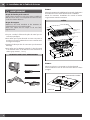
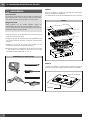
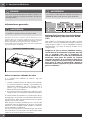
TOOLS WILL YOU NEED
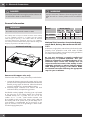
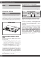
STEP 1
Remove packaging materials and literature package from the
cooktop before beginning installation. Remove Installation
Manual from literature pack and read them carefully before
you begin.
PARTS
COOKTOP
CARDBOARD
TOP-CARDBOARD
MANUAL
GASKET
SCRAPER
TOP PACKAGING
BOTTOM PACKAGING
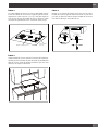
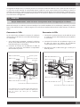
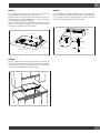
STEP 2
Place a towel or table cloth onto the counter top. Lay the
cooktop upside down onto the protected surface.
COOKTOP HOUSING
TABLE CLOTH

EN
7
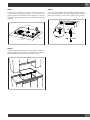
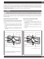
STEP 3
A foam tape is provided to seal the cooktop edges to the
countertop. Apply tape approximately 1/16” (1.5 mm) from
the glass edge to the underside of the cooktop glass. Use tape
around the entire glass perimeter. Cut off excess where tape
ends butt.
COOKTOP HOUSING
COOKTOP GLASS
FOAM TAPE SEAL
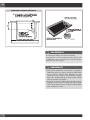
STEP 4
Insert the cooktop centered into the cutout opening. Make sure
the front edge of the counter top is parallel to the cooktop.
Make a final check that all required clearances are met.
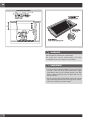
STEP 5
Four or six clamp brackets are provided to clamp the cooktop
to the countertop. Tighten screws just enough to hold brackets in
place when cooktop is put into cutout. Tighten screws securely.

EN
8
ELECTRIC OPENING
WARNING
THE ELECTRICAL CONDUIT IS 3 FEET LONG
The junction box, must be located where it will allow
considerable slack in the conduit for serviceability.
IMPORTANT
• For solid surface material installations such as Surel™ and
Corian®, consult with solid surface manufacturer. Apply
heat reflective tape such as Scotch® Aluminum Foil Tape
#425 or #427 around the cutout so that it folds over on
the top and sides.
• Do not wrap the tape underneath the cooktop. Be sure the
tape extends beyond the outermost flange of the cooktop.
All corners should be covered with tape.

EN
9
4 - Cooktop Installation Over a Single Oven
CAUTION
• Use the countertop opening dimensions that are given with
these Instructions.
• Check the cooktop base for an approved installation label.
Verify approved oven model numbers that can be installed
with your cooktop model number.
• The cooktop may be installed over a single oven.
• The cooktop should be centred over the oven.
• Both the cooktop and the oven must be installed according
to each specific installation instruction.
* The ventilation opening is to extend the full length of the cooktop cutout.
25” (635mm)
min
19 7/16” (494mm)
3”
(76mm)
2 1/2”
(65mm)
1 5/8”
(40mm)
max
1/4”
(6mm)
min
4”
(101mm)
min
4 3/4”
(120 mm)
36”
(915mm)
27 1/4”
(692mm)
1 1/2”
(38 mm)
min
24” (610mm)
min
*1/4”
(6mm)
min
2 1/2”
(64mm)

EN
10
5 - Electrical Connections
DANGER
Disconnect power before servicing the product. Failure to do
so could result in death or electrical shock.
General information
WARNING
The models may be powered at 240V or 208V.
This cooktop does not require a neutral connection. If the cooktop
is to be completely enclosed in a cabinet, feed the cooktop
cable through the opening in the cabinet. Make the electrical
connection following the appropriate steps for your installation.
Your cooktop must be connected to the proper electrical voltage and
frequency as specified in the table on the right.
Location of serial tag
Connect with copper wire only
If the house has aluminum wiring, follow the procedure below:
1. Connect the aluminum wiring to the copper wire by using
special connectors designed and Underwriters Laboratories-
listed for joining copper to aluminum. Follow the electrical
connector manufacturer’s recommended procedure.
2. Aluminum/copper connection must conform with local
codes and industry- accepted wiring practices.
The flexible conduit (supplied) 3 feet long (100 cm) located
at the right rear of the cooktop bottom box should be
connected directly into a junction box. Do not cut the
conduit. A U.L - or CSA - listed conduit connector must
be provided at each end of the power supply cable (at
the cooktop and at the junction box.) A time delay fuse or
circuit breaker is recommended. Do not ground to a gas
pipe. Do not have a fuse in the grounding or neutral circuit.
Fuse both supply (phase) lines.
WARNING
Improper connection of aluminum house wiring to the copper
leads can result in a serious problem such as an electrical
fire.
Model Power Supply
240 V 60
Hz 208 V 60
Hz Approval
code
30”
F7IT30*1 7,2kW 30A 6,30 30A 815T40*T
36”
F7IT36*1 10,8kW 45A 9,4kW 45A 815V50*U
National Fire Protection Association Battery-
march Park, Quincy, Massachusetts 02169-
7471
A three-wire, single phase, 240 Volt 60 cycle electrical system
(properly circuit protected to meet Local Codes of NFPA
No.70) must be provided. Unit must be properly grounded in
accordance with local wiring code.
Be sure your appliance is properly installed and
grounded by a qualied technician. Ask your
dealer to recommend a qualied technician or an
authorized repair service. This cooktop does not
require a neutral connection. If the cooktop is to be
completely enclosed in a cabinet, feed the cooktop
cable through the opening in the cabinet. Make
the electrical connection following the appropriate
steps for your installation.

EN
11
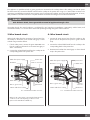
3-Wire branch circuit
Where local codes allow the connection of ground wire from
the cooktop to the branch circuit neutral wire (gray or white
colored wire) proceed as follows.
1. If local codes permit, connect the green GROUND wire
from the cooktop to the branch circuit neutral wire (gray or
white colored wire).
2. Connect the red and black leads from the cooktop to the
corresponding leads in the junction box.
Cable from power supply
Red Wires
White Wires
Bare or green wires
3-Wire cable from cooktop
Where local codes permit connecting the frame-ground
conductor to the neutral (white) junction box wire.
(Not used for Canadian installations)
Junction box
Twist-on connector
Black wires
U.L.-or CSA-listed conduit connector
4--Wire branch circuit
1. Connect the green ground wire from the cooktop to the
ground wire in the junction box (bare or green colored
wire).
2. Connect the red and black leads from the cooktop to the
corresponding leads in the junction box.
3. Terminate and insulate the neutral (gray or white colored
wire) in the junction box.
Red wires
Bare or green wires
3-Wire cable from cooktop
Twist-on
connector
Black wires
U.L. - or CSA-listed conduit connector
Junction box
White wire
Cable from power supply
This appliance is manufactured with a green ground wire connected to the cooktop chassis. After making sure that the power
has been turned off, connect the flexible conduit from the cooktop to the junction box using a U.L. listed conduit connector. The
instructions provided below present the most common way of connecting the cooktops. Your local codes and ordinances, of course,
take precedence over these instructions. Complete electrical connections according to local codes and ordinances.
DANGER
Risk of Electric Shock, frame grounded to neutral of appliance through a link.
Grounding through the neutral conductor is prohibited for new branch-circuit installations (1996 NEC); mobile homes; and
recreational vehicles, or in an area where local codes prohibit grounding through the neutral conductor.

12
Notes

FR
1
TABLES DES MATIERES
PAGE
1 - Avertissement Spéciaux 2
Avant de Procéder à l’Installation 2
2 - Dimensions du Produit et Découpe 3
Conseils importants de préparation 5
3 - Installation de la Table de Cuisson 6
4 - Installation de la Plaque de Cuisson
sur un Four Simple 9
5 - Connexions Electriques 10
Informations générales 10
Connexion à 3 fils 11
Connexion à 4 fils 11
IMPORTANT: Gardez ces instructions pour une utilization
d’inspection électrique locale
INSTALLATEUR: Veuillez laisser ce manuel au
propriétaire pour de futures références.
PROPRIETAIRE: Veuillez garder ce manuel pour de
futures références.
Veuillez prêter attention à ces symboles que vous
rencontrerez dans ce manuel
DANGER
Si vous ne suivez pas IMMEDIATEMENT ces instructions,
vous courez le risque de mourir ou d’être sérieusement
blessé.
AVERTISSEMENT
• Ce symbole signifie que la sécurité est en danger. Il signale
les risques potentiels qui peuvent entraîner la mort ou des
blessures à l’opérateur ou aux autres.
• Si vous ne suivez pas ces instructions à la lettre, vous
courez le risque de mourir ou d’être sérieusement blessé.
AVERTISSEMENT
• La non-observation des instructions contenues dans ce
manuel peut entraîner la mort ou des blessures sérieuses
du fait d’un incendie ou d’une explosion.
• Ne pas stocker ou utiliser de l’essence ou d’autres liquides
inflammables à proximité de cet appareil ou de tout autre
appareil électroménager.

FR
2
1 - Avertissement Spéciaux
Il est de votre responsabilité d’installer l’appareil correctement.
Confiez l’installation de cette table de cuisson à un technicien
qualifié.
IMPORTANT
• Respecter les règlements et ordonnances en vigueur.
• Avant d’installer la table de cuisson, veuillez noter les
numéros de modèle et de série. Ces deux numéros se
trouvent sur la plaquette signalétique située en dessous de
la caisse de la table de cuisson.
Avant de Procéder à l’Installation
AVERTISSEMENT
La responsabilité revient au client de contacter un électricien
installateur qualifié. Veuillez vous assurer que l’installation
électrique est adéquate et conforme à la réglementation
électrique nationale : ANSI/NFPA 70 -dernière édition
** ou normes CSA C22.1-94, réglementation électrique
canadienne, partie No.0-M91 – dernière édition *** et
tous les règlements et ordonnances locaux.
Copies des normes mentionnées ci-dessus peuvent être obtenues:
** National Fire Protection Association One Batterymarch Park
Quincy, Massachusetts 02269
*** CSA International 8501 East Pleasant Valley Rd. Cleveland,
OH 44131-5575
Pour éviter le risque de brûlures en touchant les surfaces
chauffées, l’espace de stockage du meuble au
dessus des unités de surface doit être évité. Si le
meuble de stockage est fourni, le risque peut être réduit
en installant une hotte qui projète horizontalement
un minimum de 5” (12,7 cm) sous le dessous
du meuble.
AVERTISSEMENT
Veuillez lire les instructions avant toute utilisation

FR
3
2 - Dimensions du Produit et Découpe
30”
30” 3/8
(771 mm)
21” 3/16
(538 mm)
1/4”
(6mm)
2” 5/8
(66 mm)
1” 1/16
(27 mm)
36”
36” 3/16
(919 mm)
21” 3/16
(538 mm)
1/4”
(6mm)
2” 5/8
(66 mm)
1” 1/16
(27 mm)
DIMENSION DE LA DÉCOUPE
LONGUEUR DE DÉCOUPE
A
LONGUEUR DE DÉCOUPE
B
1-1/2” (3.8CM)
ESPACE MINIMUM
VOIR NOTE
R
DU BORD DE LA DÉCOUPE
AU BORD ANTÉRIEUR DU
PLAN DE TRAVAIL
2-1/2” (6.5 cm)

FR
4
DISPOSITIONS POUR LA DÉCOUPE
D
G
C
E
F
LES REVETEMENTS DES MEUBLES ET LE
PLAN DE TRAVAIL DOIVENT RESISTER A
UNE CHALEUR DE 93° C (200° F)
Découpe
largeur A B C
30”
(76.2cm) 28-3/4” +/- 1/16”
(73.0 cm +/- 0.1cm)
19-7/16” +/- 1/16”
(49.4 cm +/- 1mm)
30”
(76.2 cm) min
36”
(91.4cm) 34-5/8” +/- 1/16”
(87.9 cm +/- 0.1cm)
19-7/16” +/- 1/16”
(49.4 cm +/- 1mm)
36”
(91.4 cm) min
Découpe
largeur D E F G
30”
(76.2cm) 18”
(45.7 cm) min
Hauteur min. du plan de
travail au meuble le plus
près des deux cotés de
l’appareil
30”
(76.2 cm) min.
(voir note*) Du plan de
travail à la surface non
protégée à la verticale
2”
(5 cm) min
Espace min. de la
découpe à la paroi
latérale sur la gauche et
la droite de l’appareil
13”
(33 cm)
Profondeur des meubles
non protégées à la
verticale
36”
(91.4cm)
IMPORTANT
En dessous de la table de cuisson, il est nécessaire d’installer
une cloison.
NOTE: 24” (61 cm) espace min. si le bas des meubles en bois
ou en métal est protégée par au moins 1/4“ (0,6 cm) de
carton-reliure ignifuge avec une tôle d’acier inoxydable No.
28 MSG d’au moins 0.015” (0,04 cm), ou d’aluminium
0.024” (0,06 cm) ou de cuivre 0.020” (0,05cm).
30” (76,2 cm) d’espace min. entre le haut de la plate-
forme de cuisson et le bas du meuble non-protégé en bois
ou métal.
La page charge ...
La page charge ...
La page charge ...
La page charge ...
La page charge ...
La page charge ...
La page charge ...
La page charge ...
La page charge ...
La page charge ...
La page charge ...
La page charge ...
La page charge ...
La page charge ...
La page charge ...
La page charge ...
La page charge ...
La page charge ...
La page charge ...
La page charge ...
La page charge ...
La page charge ...
La page charge ...
La page charge ...
-
 1
1
-
 2
2
-
 3
3
-
 4
4
-
 5
5
-
 6
6
-
 7
7
-
 8
8
-
 9
9
-
 10
10
-
 11
11
-
 12
12
-
 13
13
-
 14
14
-
 15
15
-
 16
16
-
 17
17
-
 18
18
-
 19
19
-
 20
20
-
 21
21
-
 22
22
-
 23
23
-
 24
24
-
 25
25
-
 26
26
-
 27
27
-
 28
28
-
 29
29
-
 30
30
-
 31
31
-
 32
32
-
 33
33
-
 34
34
-
 35
35
-
 36
36
-
 37
37
-
 38
38
-
 39
39
-
 40
40
-
 41
41
-
 42
42
-
 43
43
-
 44
44


