Kobalt 0300842 Manuel utilisateur
- Catégorie
- Compresseurs d'air
- Taper
- Manuel utilisateur

AB171071
KOBALT® and the K Design® are registered
trademarks of LF, LLC. All Rights Reserved.
ITEM #0470442
8 GAL. OIL-FREE AIR COMPRESSOR
MODEL #0300841
Français p. 14
Español p. 27
Questions, problems, missing parts? Before returning to your retailer, call our customer
service department at 1-888-3KOBALT (1-888-356-2258), 8 a.m. - 8 p.m., EST,
Monday - Friday.
ATTACH YOUR RECEIPT HERE
Serial Number Purchase Date
1

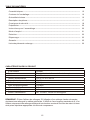
TABLE OF CONTENTS
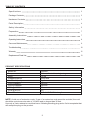
PRODUCT SPECIFICATIONS
Model No. 0300841
Power Cord
CFM @ 90 PSI
CFM @ 40 PSI
Cut-out Pressure
Cut-in Pressure
Air Tank Capacity
Voltage/Amps/Hz
SJT 16 AWG / 72 in. length
4.0
5.0
150 PSI
120 PSI
8 gallon
120/12.5/60
Pump
Motor 1.8 Hp
Oil free, direct drive, single stage
NOTE: Avoid use of extension cords. If use of an extension cord cannot be avoided, the cord
should be a minimum wire size of 12 AWG and no longer than 30 feet.
Use only a 3-wire extension cord that has a 3-blade grounding plug and a 3-slot receptacle that
will accept the plug on the product.
Specifications
2
Package Contents
3
Hardware Contents
3
4
Parts Description
5
Safety Information
7
Assembly Instructions
8
Operating Instructions
9
Care and Maintenance
10
Troubleshooting
12
Warranty
13
Replacement Parts List
7
Preparation
2

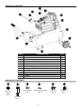
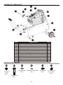
PACKAGE CONTENTS
HARDWARE CONTENTS
Screw
Qty. 2
M8 × 15
Qty. 2
M10 Bolt
Qty. 2
Ø10 Washer
Qty. 2
Ø10 Spring Washer
Qty. 2
M10 Nut
PART QTY
A
Electric Motor & Air Compressor Pump
B Air Tank
Tank Pressure Gauge
C
D
Air Pressure Regulator
E Regulated Pressure Gauge
Quick Coupler
F
G Air Tank Drain Valve
Pressure Relief Valve
H
1
1
1
1
1
1
1
1
1
1
I ON/OFF Switch
J Power Cord
K
Handle Kit
L Wheel
Air Filter
M
1
2
1
DESCRIPTION
AA BB CC DD EE
Qty. 2
Wheel Cap
FF
3

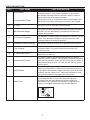
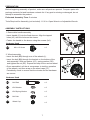
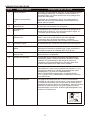
PARTS DESCRIPTION
PART PART NAME PART DESCRIPTION
A Electric Motor
The motor is used to power the pump. It contains a thermal
overload protector. If the motor overheats for any reason,
the thermal overload protector will shut it down in order to
prevent the motor from being damaged.
The pump is used to compress the air and discharge it into
the tank via the piston moving up and down in the cylinder.
B Air Tank The tank is used to store the compressed air.
C Tank Pressure Gauge
The gauge is used to measure the stored air pressure level of
the tank. It is not adjustable by the op
erator and does not
indicate line pressure.
D Air Pressure Regulator
The regulator is used to adjust line pressure to the tool you are
using. Turn the knob clockwise to increase pressure and
counterclockwise to decrease pressure.
E Regulated Pressure Gauge The gauge is used to measure the regulated outlet pressure.
F Quick Coupler
For this compressor, the quick coupler is also used as
the air line outlet. The outlet is used to connect the 1/4
in. NPT air hose.
G Air Tank Drain Valve
The drain valve is used to remove moisture from the air tank
after the unit is shut off.
H Pressure Relief Valve
The valve is used to prevent system failures by relieving
pressure from the system. If the pressure reaches the preset
level and the pressure switch will not shut down the motor, it
will automatically pop open. You can also pull the ring on the
valve to open.
I On/Off Switch
J Power Cord
Grounded
outlet
Grounding Pin
Plug
Air Compressor Pump
This switch turns on the compressor and is operated manually.
When in the ON position, it allows the compressor to start up
or shut down automatically, without warning, upon air demand.
ALWAYS set this switch to OFF when the compressor is not
being used and before unplugging the compressor.
This product is for use on a nominal 120-volt circuit and
should be grounded. A cord with a grounding plug as
illustrated must be used. Make sure that the product is
connected to an outlet that has the same configuration as
the plug. No adapter should be used with this product.
4

SAFETY INFORMATION
5
DANGER: Someone will be seriously injured or killed if the safety information is not followed.
DANGER
Improper installation of the grounding plug will result in a risk of electric shock. If repair or
blade terminal. The grounding wire has a green outer surface.
WARNING: Someone will be seriously injured or killed if the safety information is not followed.
CAUTION: Someone may be injured if the safety information is not followed.
WARNING
•
motor and pressure switch to produce sparks while operating. If sparks come into contact with
as far from the spray area as possible. Always operate the compressor in a well-ventilated area.
•
Risk of electric shock. A licensed electrician must install all wiring in accordance with all local
and national codes. To avoid electric shock, never use an electric air compressor outdoors
when it is raining or on a wet surface.
• Risk of bursting. Rust can weaken the tank. Drain the condensed water from the tank after
each use to reduce rusting. Do not weld, drill or modify the air tank of this compressor. Welding
hazardous condition. If a leak is detected in the tank, replace the tank immediately.
• Risk of injury. Always shut off the compressor, remove the plug from the outlet and bleed all
pressure from the system before servicing the compressor or when the compressor is not in
use. Do not use the unit with the shrouds removed. Contact with moving parts could cause
serious injury.
•
Risk of bursting. Check the maximum pressure rating in the manual or the serial tag label.
Compressor outlet pressure must be regulated so as to never exceed the maximum pressure
rating. Relieve all pressure through the hose before removing or attaching accessories.
Please read and understand this entire manual before attempting to assemble, operate or install
the product. If you have any questions regarding the product, please call customer service at
1-888-3KOBALT, 8 a.m. - 8 p.m., EST, Monday - Friday.
Safety Symbols
The purpose of safety symbols is to attract your attention to possible dangers. The safety
symbols and the explanations that accompany them deserve your careful attention and
understanding. The safety warnings DO NOT, by themselves, eliminate any danger. They are not
substitutes for proper accident-prevention measures.
User Safety

Risk of bursting. Do not adjust the pressure switch or relief valve for any reason. They
have been preset at the factory for the maximum pressure of this unit. If the pressure
switch or the relief valve are tampered with, personal injury or property damage may occur.
•
Risk of burns. The pump and manifold generate high temperatures. To avoid burns or
other injuries, do not touch the pump, manifold or transfer tube while the unit is running.
Allow the parts to cool before handling or servicing. Keep children away from the
compressor at all times.
•
Risk to breathing. Read all labels when you are spraying paints or toxic materials, and
follow the safety instructions. Use a respirator mask if there is a chance of inhaling
anything you are spraying. Never directly inhale the compressed air produced by a
compressor.
•
Risk of eye injury. Always wear ANSI 287.1 approved safety goggles when using an air
compressor. Never point the nozzle or sprayer toward a person or any part of the body.
If the spray penetrates the skin, serious injury may occur.
•
Never exceed the maximum working pressure of the tool.•
Never attempt to open the drain valve when the tank pressure is more than 10 PSI.•
You can create dust when you cut, sand, drill or grind materials such as wood, paint,
metal, concrete, cement, or other masonry. This dust often contains chemicals known
to cause cancer, birth defects, or other reproductive harm. Wear protective gear.
•
Pull the pressure relief valve ring daily to ensure the valve is functioning properly.•
The unit must be kept a minimum of 12 in. from the nearest wall, in a well-ventilated area
for cooling.
•
Protect the air hose and electric cord from damage and puncture. Inspect them weekly for
weak or worn spots and replace if necessary.
•
Always wear hearing protection when using an air compressor. Failure to do so may result
in hearing loss.
•
Operation of the unit should always be in a position that is stable. Never use the unit on
a rooftop or elevated position that could allow the unit to fall or be tipped over.
•
CAUTION
6
SAFETY INFORMATION

PREPARATION
Before beginning assembly of product, make sure all parts are present. Compare parts with
package contents list and hardware contents list. If any part is missing or damaged, do not
attempt to assemble the product.
Estimated Assembly Time: 5 minutes
Tools Required for Assembly (not included): 11/16 in. Open Wrench or Adjustable Wrench.
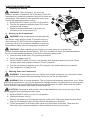
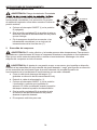
ASSEMBLY INSTRUCTIONS
Hardware Used
1. Removable handle assembly
• Insert handle (K) into the fixed sleeves. Align the tapped
holes (K1) with the holes on the sleeve.
• Fasten the handle to the sleeve using the screws (AA).
M8 × 15 Screw
x 2
AA
Hardware Used
2. Wheel assembly
• Insert the bolt (BB) through one of the wheels (L).
• Insert the bolt (BB) through the bracket on the bottom of the
tank assembly. Slide on washer (CC), spring washer (DD)
and tighten the nut (EE). Repeat this step for the second wheel.
• Once assembled, roll the air compressor to test the operation
of the wheels, and then snap on the wheel caps (FF).
Periodically check to ensure that the wheels and the hardware
are secure.
M10 Bolt
x 2
BB
Ø10 Washer
x 2
CC
Ø10 Spring Washer
x 2
DD
M10 Nut
x 2
x 2
EE
M
Wheel Cap
FF
K
1
AA
K1
2
CC
DD
EE
BB
L
FF
7

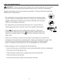
OPERATING INSTRUCTIONS
1. Preparing for Startup
WARNING: Risk of bursting. Too much air
pressure causes a hazardous risk of bursting. Check the
manufacturer’s maximum pressure rating for air tools and
accessories. The regulator outlet pressure must never
exceed the maximum pressure rating
a. Set the ON/OFF switch (I) to the O (off) position.
b. Turn the air pressure regulator knob (D) counter
clockwise until it stops.
c. Attach air hose/accessories or air tools (not
included) to the quick coupler (F).
2. Starting up the Compressor
WARNING: High temperatures are generated by
the electric motor and the pump. To prevent burns or
other injuries, DO NOT touch the compressor while it
is running. Allow it to cool before handling or servicing.
Keep children away from the compressor at all times.
WARNING: When adjusting from a higher to a lower pressure, turn the knob
counterclockwise past the desired setting. Then turn clockwise to reach the desired pressure.
Do not exceed operating pressure of the tool or accessory being used.
a. Close the tank drain valve (G) by turning clockwise.
b. Plug in the power cord (J).
c. Set the ON/OFF switch (I) to the I (on) position and allow tank pressure to build. Motor
will stop when tank pressure reaches “cut-out” pressure.
d. Turn the air pressure regulator knob (D) clockwise until desired pressure is reached.
e. The compressor is ready for use.
J
G
H
F
D
I
OPEN
CLOSE
ON
OFF
3. Shutting Down the Compressor
WARNING: To avoid personal injury, always shut off and unplug the unit, and relieve all air
pressure from the system before performing any service on the air compressor.
WARNING: Risk of unsafe operation. The unit cycles automatically when power is on. When
performing maintenance, you may be exposed to voltage sources, compressed air or moving parts.
Personal injuries can occur. Before performing any maintenance or repair, disconnect the power
source from the compressor and bleed off all air pressure.
CAUTION: Escaping air and moisture can propel debris that may cause eye injury. Wear
safety goggles when opening the drain valve.
a. Set the ON/OFF switch (I) to the O (off) position.
b. Unplug the power cord (J).
c. Reduce the pressure in the tank through the outlet hose. Pulling the pressure relief valve
ring (H) and keeping it open will also reduce the pressure in the tank.
d. Tip the compressor so the tank drain valve is at the bottom of the tank. Then open the
tank drain valve counterclockwise to allow moisture to drain from the tank.
8

CARE AND MAINTENANCE
WARNING: To avoid personal injury, always shut off and unplug the unit and relieve
all air pressure from the system before performing any service on the air compressor.
Regular maintenance will ensure trouble-free operation. The items listed here should be
inspected on a regular basis.
• On a daily basis, drain the tank to prevent corrosion from forming inside
the tank. Drain the condensation at the end of every day. Wear protective
goggles. Relieve the air pressure in the system and then open the drain
valve (G) on the bottom of the tank.
• On a daily basis, pull the pressure relief valve (H) to ensure that it is
operating properly and to clear the valve of any possible obstructions.
• A dirty
will reduce the unit’s performance and life. To avoid any
contamination inside the pump, the
should be cleaned weekly and
replaced on a regular basis. Foam
should be cleaned in warm and
soapy water.
• Check all connections to ensure they are tight. A small leak from any part of the
compressor will reduce the unit’s performance. Spray a small amount of soapy water
around the area of the suspected leak with a spray bubble. If bubbles appear,
repair or replace the faulty component. Do not overtighten any connections.
• Before storing the unit for a long period, do the following:
• Use an air blow gun (not included) to clean all dust and debris from the compressor.
• Disconnect and coil the power cord.
• Pull the pressure relief valve to release all pressure from the tank.
• Drain all moisture from the tank.
• Cover the entire unit to protect it from moisture and dust.
I
9
I

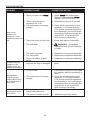
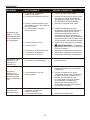
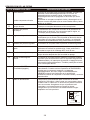
TROUBLESHOOTING
PROBLEM POSSIBLE CAUSE CORRECTIVE ACTION
There is low
pressure, not
enough air, or the
compressor does not
stop.
1. The tank drain valve is open.
2. There is a leak in the
3. There is a prolonged or
excessive use of air.
4. The compressor is not large
enough.
5. There is a hole in the air hose.
6. The tank leaks.
7. The seals are blown.
8. The valve leaks.
9. There is a leaking or worn
piston.
1. Close the drain valve.
2. Check
with soapy water.
Tighten or reseal leaking
DO NOT OVERTIGHTEN.
3. Decrease the amount of air used.
4. Check the air requirement of the
accessory. If it is higher than the
CFM and the pressure supplied by
the compressor, you need a larger
compressor. Most accessories are
rated at 25% of the actual CFM
while running continuously.
5. Check and replace if necessary.
6.
WARNING: Immediately
replace the tank. DO NOT attempt
to repair.
7. Replace the compressor assembly.
8 Replace the compressor assembly.
9. Replace the compressor assembly.
Air leaks from the
regulator or the
regulator does not
regulate air pressure.
1. The internal parts of the
regulator are dirty or damaged.
1. Replace the regulator or internal
parts.
The regulated
pressure gauge
reading drops when
the air accessory is
being used.
1. This is normal.
2. The compressor is not large
enough.
1. If the pressure drops too low, adjust
the regulator while the accessory is
used.
2. Check the air requirement of the
accessory. If it is higher than the
CFM and the pressure supplied by
the compressor, you need a larger
compressor. Most accessories are
rated at 25% of the actual CFM
while running continuously.
The pressure relief
valve opens.
1. The tank pressure exceeds the
normal rating pressure.
2. The pressure switch is stuck.
1. Replace the pressure switch.
2. Replace the pressure switch.
10

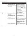
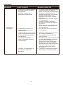
TROUBLESHOOTING
PROBLEM POSSIBLE CAUSE CORRECTIVE ACTION
The motor will not
run.
1. Tank pressure exceeds the
preset pressure switch limit.
2. The fuse is blown or the circuit
breaker tripped.
3. The check valve is stuck in the
open position.
4. The wire gauge in the cord is
wrong or the extension cord
length is excessive.
5. There are loose electrical
connections.
6. The motor’s thermal overload
protection has tripped.
7. The motor, capacitor or safety
valve is defective.
1. The motor will start automatically
when the tank pressure drops
below the tank cut-in pressure.
2. Replace the blown fuse or reset
the circuit breaker. Do not use a
fuse or circuit breaker with a higher
circuit.
Check for proper fuse; type T fuse
is acceptable.
Check for low voltage and proper
extension cord size.
Disconnect other applications from
the circuit. Operate the compressor
on a dedicated circuit.
3. Remove and clean or replace.
4. Check for proper gauge and
extension cord length.
5. Contact an authorized service
center.
6. Turn the air compressor off, unplug
7. Have the compressor serviced by a
qualified technician.
the power cord and wait until the
motor has cooled down. Plug in
the power cord only after the motor
has cooled down, waiting
thermal overload protector has
the
recovered.
11

ONE YEAR LIMITED WARRANTY
This product is guaranteed for a period of one year from the date of original retail purchase
against defects in materials and workmanship.
Subject to the conditions and limitations described below, this product, if returned to us with
proof of purchase within the stated warranty period and if covered under this warranty,
be repaired or replaced (with the same model, or one of equal value or specification), at our
option. We will bear the cost of any repair or replacement and any cost of labor relating thereto.
This warranty is subject to the following conditions and limitations:
a. A bill of sale verifying the purchase and purchase date must be provided.
b. This warranty will not apply to any product or part which is worn or broken or which has
become inoperative due to abuse, misuse, accidental damage, neglect or lack of proper
installation, operation or maintenance (as outlined in the applicable owner’s manual or
operating instructions) or which is being used for industrial, professional, commercial or rental
purposes.
c. This warranty will not apply to normal wear and tear or to expendable parts or accessories
that may be supplied with the product which are expected to become inoperative or unusable
after a reasonable period of use.
d. This warranty will not apply to routine maintenance and consumable items such as, but not
limited to, fuel, lubricants, vacuum bags, blades, belts, sandpaper, bits, fluids, tune-ups or
adjustments.
e. This warranty will not apply where damage is caused by repairs made or attempted by others
(i.e. persons not authorized by the manufacturer).
This warranty will not apply to any product that was sold to the original purchaser as a
reconditioned or refurbished product (unless otherwise specified in writing).
f.
This warranty will not apply to any product that was sold to the original purchaser as a
reconditioned or refurbished product (unless otherwise specified in writing).
g. This warranty will not apply to any product or part thereof if any part from another
manufacturer is installed therein or any repairs or alterations have been made or attempted
by unauthorized persons.
This warranty will not apply to normal deterioration of the exterior finish, such as, but not
limited to, scratches,dents,paint chips, or to any corrosion or discoloring by heat, and
abrasive chemical cleaners.
h.
This warranty will not apply to component parts sold by and identified as the product of
i.
another company, which shall be covered under the product manufacturer warranty, if any.
12

Printed in China
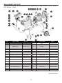
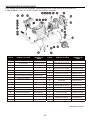
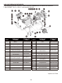
REPLACEMENT PARTS LIST
Rubber hose
Pressure gauge
Relief valve
Handle
Quick coupler
Thumbscrew
Regulator
Front shround
On/off switch
Check valve
Wheel Kit
Vibration Pad Kit
Drain valve
Air tank
Elbow
Pump/Motor assembly
Run Capacitor,60 μf
Start Capacitor,250 μf
Fan
Air filter
Back shroud
Bolt M5
×12
Self-tapping screw ST3.9
×16
Self-tapping screw ST3.9
×12
Control panel
Bolt M8x25
Washer Ø8
Cushion pad
Bolt M5x10
Lock washer
Transfer tube
Pressure switch
Anchor nut
Power cord
For replacement parts, call our customer service department at 1-888-3KOBALT, 8 a.m. - 8 p.m.,
EST, Monday - Friday
CE0701W.50.00
CE0701W.70.00
CC0701.40.01
WCFATY.02.07
WCYBZX.01.41
5104-0040-01
5106-0010-01
J0781110033
CE0701W.40.01
5607-0020-01
CE0701W.00.04
WCFADX.02.03
5808-0390-01
J0781000033
D6009006001
5612-0100-01
CE0701W.20.00
CE0701W.00.03
2263C064
CE0701W.80.00
CE0701W.30.00
J0801100033
BQL201.39.02
MI0501.00.09
CE0701W.00.02
5602-0120-01
5816-0040-01
5802-0190-01
CE0701W.00.10
CE0701W.10.00
CE0501W.00.06
CE0701W.00.01
5105-0030-01
CE0701W.00.20
1
2
3
4
5
6
7
8
9
11
10
12
13
41
51
61
71
21
20
19
18
22
23
24
25
26
27
28
29
30
31
32
33
34
PART PART NAME PART# PART PART NAME PART#
13

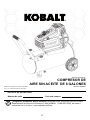
KOBALT
®
et le motif K
®
sont des marques de commerce
déposées de LF, LLC. Tous droits réservés.
COMPRESSEUR D’AIR
SANS HUILE DE 30,28 L
ARTICLE #0470442
MODÈLE #0300841
Des questions, des problèmes, des pièces manquantes? Avant de retourner l’article
au détaillant, appelez notre service à la clientèle au 1 888 3KOBALT (1 888 356-2258),
entre 8 h et 20 h (HNE), du lundi au vendredi.
JOIGNEZ VOTRE REÇU ICI
Numéro de série Date d’achat
14

TABLE DES MATIÈRES
CARACTÉRISTIQUES DU PRODUIT
REMARQUE : Évitez d’utiliser des rallonges. Si l’utilisation d’une rallonge s’avère nécessaire,
choisissez une rallonge d’un calibre minimal de 12 AWG et d’une longueur maximale de 9,14 m.
Utilisez uniquement des rallonges trifilaires à trois broches munies d’une fiche de mise à la terre
et de prises tripolaires appropriées à la fiche du compresseur.
Caractéristiques ----------------------------------------------------------------------------------------------
Contenu de l’emballage------------------------------------------------------------------------------------
Quincaillerie Incluse ------------------------------------------------------------------------------------------
Description des pièces---------------------------------------------------------------------------------------
Consignes de sécurité--------------------------------------------------------------------------------------
Préparation -----------------------------------------------------------------------------------------------------
Instructions pour l’assemblage --------------------------------------------------------------------------
Mode d’emploi-------------------------------------------------------------------------------------------------
Entretien---------------------------------------------------------------------------------------------------------
Dépannage ------------------------------------------------------------------------------------------------------
Garantie ----------------------------------------------------------------------------------------------------------
Liste des pièces de rechange -------------------------------------------------------------------------------
15
16
16
17
18
20
20
21
22
23
25
26
N
o
de modèle
Pompe
Moteur
Tension d’alimentation
Capacité du réservoir d’air
Point d’enclenchement
Point de déclenchement
pi
3
/min à 40 lb/po
2
pi
3
/min à 90 lb/po
2
Cordon d’alimentation
0300841
Sans huile, à entraînement direct, à une phase
1,8 HP
120 V / 12.5 A / 60 Hz
30,28 L
120 lb/po
2
150 lb/po
2
5,0
4,0
SJT 16 AWG, 182,88 cm de longueur
15

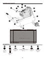
CONTENU DE L’EMBALLAGE
PIÈCE QTÉDESCRIPTION
A Moteur électrique et pompe de compresseur d’air 1
B Réservoir d’air 1
C Manomètre du réservoir 1
D Régulateur de pression d’air 1
E Manomètre régulé 1
F Raccord à branchement rapide 1
G Robinet de vidange du réservoir d’air 1
H Soupape de décharge 1
I Interrupteur 1
J Cordon d’alimentation 1
K Poignée 1
L Roue 2
M Filtre à air 1
QUINCAILLERIE INCLUSE
Qté. 2
Vis M8 de
15 mm
Qté. 2
Boulon M10
Qté. 2
Rondelle Ø10
Qté. 2
Rondelle à ressort Ø10
Qté. 2
Écrou M10
AA BB CC DD EE
Qté. 2
Les enjoliveurs
de roulettes
FF
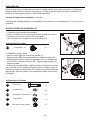
16

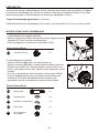
DESCRIPTION DES PIÈCES
PIÈCE
A
Moteur électrique Le moteur sert à alimenter la pompe. Il comprend un limiteur
de surcharge thermique. Ce limiteur arrête le moteur s’il
surchauffe pour une raison quelconque et le protège ainsi
contre les dommages.
La pompe sert à comprimer l’air et à le stocker dans le
réservoir par la course ascendante et descendante d’un
piston dans le cylindre.
B Réservoir d’air Le réservoir sert à stocker l’air comprimé.
C Manomètre du
réservoir
Le manomètre sert à mesurer le niveau de la pression d’air
stocké dans le réservoir. Vous ne pouvez pas le régler, et
il n’indique pas la pression de conduite.
D Régulateur de
pression d’air
Le régulateur sert à régler la pression de conduite de l’outil
utilisé. Tournez le bouton dans le sens des aiguilles
d’unemontre pour accroître la pression, ou dans le
sens contraire des aiguilles d’une montre pour la réduire.
E Manomètre régulé Le manomètre sert à mesurer la pression de sortie régulée.
F Raccord à branchement
rapide
Dans ce compresseur, le raccord à branchement rapide sert
également de sortie à la conduite d’air. Cette sortie sert à
raccorder le tuyau à air à filetage NPT de 6,35 mm
G Robinet de vidange du
réservoir d’air
Le robinet de vidange purge l’humidité du réservoir d’air
après l’arrêt du compresseur.
H Soupape de décharge
La soupape sert à évacuer la pression de l’appareil afin
d’éviter une panne. Lorsque la pression atteint un niveau
préétabli, si le pressostat n’a pas coupé le moteur, la
soupape s’ouvre automatiquement. Elle peut aussi être
ouverte manuellement en tirant surson anneau.
I Interrupteur
J Cordon d’alimentation
Prise mise
à la terre
Broche de mise à la terre
Fiche
Pompe de compresseur
d’air
Cet interrupteur met en marche le compresseur et est activé
manuellement. Lorsqu’il est en position de marche (« I »), le
compresseur démarre et s’arrête automatiquement, sans
avertissement, à la suite d’une demande d’air.
Mettez TOUJOURS cet interrupteur en position d’arrêt
(« O ») lorsque vous n’utilisez pas le compresseur ou avant
de le débrancher.
Cet appareil doit être utilisé sur un circuit d’une tension
nominale de 120 volts et mis à la terre. Vous devez employer
un cordon d’alimentation muni d’une fiche de miseà la terre
(semblable à celui qui figure sur l’illustration). Assurez-vous de
brancher le compresseur sur une prise ayant les mêmes
caractéristiques que la fiche. N’utilisez pas d’adaptateur pour
brancher le compresseur.
NOMDE LA PIÈCE DESCRIPTION DE LA PIÈCE
17

CONSIGNES DE SÉCURITÉ
Veuillez vous assurer de lire et de comprendre l’intégralité de ce manuel avant de tenter
d’assembler ou d’utiliser le produit. Si vous avez des questions, veuillez communiquer avec
clientèle au 1notre service à la 888 3KOBALT, entre 8 h et 20h (HNE), du lundi au vendredi.
Symboles relatifs à la sécurité
Les symboles relatifs à la sécurité servent à attirer votre attention sur les dangers possibles.
Vous devez prêter une attention particulière à ces symboles ainsi qu’aux explications qui sont
fournies et bien les comprendre. Pour éliminer tout danger, vous devez respecter les messages
d’avertissement. Ces messages ne remplacent toutefois pas les mesures appropriées de
prévention d’accidents.
18
AVERTISSEMENT:
•
•
•
•
DANGER : Le non-respect des consignes de sécurité occasionnera des blessures graves
ou mortelles.
AVERTISSEMENT : Le non-respect des consignes de sécurité peut occasionner des
blessures graves ou mortelles.
MISE EN GARDE : Le non-respect des consignes de sécurité peut occasionner des
blessures.
Sécurité des utilisateurs
DANGER : Le branchement inadéquat de la de mise à la terre entraîne un risque de
choc électrique. Si le cordon d’alimentation ou la
doivent être réparés ou remplacés, ne
branchez pas le
de mise à la terre sur une borne d’alimentation (lame). Le de mise à la terre
est celui dont la gaine est verte.
Risque d’explosion ou d’incendie. Ne vaporisez jamais de liquides
dans
clos. Il est normal que le moteur et que le pressostat produisent des
le fonctionnement. Si une étincelle entre en contact avec des vapeurs d’essence ou d’autres
étincelles durant
solvants, ils peuvent
et causer un incendie ou une explosion. Ne fumez pas
la vaporisation. Ne vaporisez pas en présence d’étincelles ou de
Tenez le
compresseurd’air aussi loin que possible de la zone de vaporisation. Faites toujours
fonctionner le compresseur dans un endroit bien ventilé.
Risque de choc électrique. Les travaux de câblage doivent être effectués
par un électricien
qualifié conformément à tous les codes locaux et nationaux.
d’éviter les chocs électriques,
n’utilisez jamais un compresseur d’air électrique à l’extérieur lorsqu’il pleut ni sur une surface
humide.
Risque d’éclatement. La rouille peut abîmer le réservoir. Videz l’eau condensée du
réservoiraprès chaque utilisation
de réduire les risques de corrosion. Évitez de souder, de
percer ou de
le réservoir d’air du compresseur. La soudure ou la modification du
réservoir d’air peut altérer sérieusement sa résistance et engendrer des conditions
extrêmement dangereuses. Si le réservoir fuit, remplacez-le immédiatement.
Risque de blessure. Assurez-vous de toujours arrêter le compresseur, de le débrancher de la
prise de courant et d’évacuer sa pression avant d’en faire l’entretien, ainsi que lorsque vous
ne l’utilisez pas. N’utilisez pas l’unité lorsque le boîtier est retiré. Un contact avec des pièces
en mouvement peut causer des blessures graves.
Risque d’éclatement.
la pression nominale maximale dans le guide ou sur l’étiquette
du numéro de série. La pression de sortie du compresseur d’air doit être réglée de façon à ne
jamais dépasser la pression nominale maximale. Évacuez toute la pression du tuyau avant de
retirer ou de raccorder des accessoires.
•
pendant
unespace

•
•
•
•
•
•
•
•
•
•
•
•
Risque d’éclatement. Ne réglez pas le pressostat ou la soupape de décharge pour quelque raison
que ce soit. Ils ont été préréglés à l’usine en fonction de la pression maximale de ce compresseur
La
de leur réglage pourrait causer des blessures ou des dommages matériels.
Risque de brûlure. La pompe et le collecteur dégagent une grande chaleur. Pour éviter les brûlures
ou d’autres blessures, ne touchez pas à la pompe, au collecteur ou au tube de transfert lorsque le
compresseur d’air est en marche. Laissez refroidir les pièces avant de les manipuler ou d’en faire
l’entretien. Gardez le compresseur hors de la portée des enfants en tout temps.
Risque d’inhalation. Lisez toutes les étiquettes et suivez les consignes de sécurité avant de
vaporiser de la peinture ou des matières toxiques. Portez un masque respiratoire s’il y a un
risque d’inhalation des matières vaporisées. N’inhalez jamais directement l’air produit par
un compresseur.
Risque de blessures aux yeux. Portez toujours des lunettes de sécurité conformes à la norme
ANSI 287.1 lorsque vous utilisez un compresseur d’air. Ne pointez jamais une buse ou un
pulvérisateur vers une personne ou une partie du corps. Le jet peut causer des blessures
graves s’il pénètre la peau.
Ne dépassez jamais la pression d’utilisation maximale de l’outil.
Vous pouvez créer de la poussière en coupant, ponçant, perçant ou meulant les matériaux tels
que le bois, la peinture, le métal, le béton, le ciment ou autre maçonnerie. Cette poussière
contient souvent des produits chimiques reconnus pour causer le cancer, les deformations
congénitales ou autres problèmes de la reproduction. Porter de l’équipement de protection.
Ne tentez jamais d’ouvrir le robinet de vidange lorsque la pression du réservoir s’élève à plus
de 10 lb/po
2
.
Tirez l’anneau de la soupape de décharge chaque jour
de si la soupape fonctionne
correctement.
Le compresseur d’air doit se trouver à au moins 30,48 cm du mur le plus s, dans un endroit
prè bien ventilé qui assurera son refroidissement.
Protégez le tuyau à air et le cordon d’alimentation contre les risques d’endommagement
et de perforation.
chaque semaine s’ils présentent des traces d’affaiblissement
ou d’usure et remplacez-les au besoin.
Portez toujours des protecteurs auditifs lorsque vous utilisez un compresseur d’air.La
non-observance de cette consigne peut entraîner une perte auditive.
Utilisez toujours l’unité sur une surface stable. N’utilisez jamais l’unité sur
un toit ou en hauteur, car elle pourrait tomber ou se renverser.
MISE EN GARDE
19
CONSIGNES DE SÉCURITÉ

PRÉPARATION
Avant de commencer l’assemblage de l’article, assurez-vous d’avoir toutes les pièces. Comparez
le contenu de l’emballage avec la liste des pièces et celle de la quincaillerie incluse. S’il y a des
pièces manquantes ou endommagées, ne tentez pas d’assembler l’article.
Temps d’assemblage approximatif : 5 minutes.
Outils nécessaires pour l’assemblage (non inclus) : clé à fourches de 11/16 po ou clé à molette.
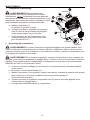
INSTRUCTIONS POUR L’ASSEMBLAGE
Quincaillerie utilisée
1. Assemblage de la poignée amovible
• Insérez la poignée (K) dans les manchons fixes. Alignez les trous
taraudés (K1) avec les trous des manchons.
• Fixez la poignée aux manchons à l’aide des vis (AA).
Vis M8 de 15 mm
x 2
AA
Quincaillerie utilisée
2. Assemblage des roulettes
• Insérez le boulon (BB) dans l’une des roulettes (L).
• Insérez le boulon (BB) dans le support situé au bas du réservoir.
Glissez une rondelle (CC) et une rondelle à ressort (DD) sur le
boulon, puis serrez l’écrou (EE). Répétez cette étape pour l’autre
roulette.
• Une fois le compresseur d’air assemblé, roulez-le pour vérifier
que les roulettes fonctionnent, puis placez les enjoliveurs de
roulettes (FF).Vérifiez périodiquement les roulettes et la
quincaillerie afin de vous assurer qu’elles sont bien fixées.
Boulon M10
x 2
BB
Rondelle Ø10
x 2
CC
Rondelle à ressort Ø10
x 2
DD
Écrou M10
x 2
EE
2
CC
DD
EE
BB
L
FF
x 2
Les enjoliveurs
de roulettes
FF
20
K
1
AA
K1
La page est en cours de chargement...
La page est en cours de chargement...
La page est en cours de chargement...
La page est en cours de chargement...
La page est en cours de chargement...
La page est en cours de chargement...
La page est en cours de chargement...
La page est en cours de chargement...
La page est en cours de chargement...
La page est en cours de chargement...
La page est en cours de chargement...
La page est en cours de chargement...
La page est en cours de chargement...
La page est en cours de chargement...
La page est en cours de chargement...
La page est en cours de chargement...
La page est en cours de chargement...
La page est en cours de chargement...
La page est en cours de chargement...
-
 1
1
-
 2
2
-
 3
3
-
 4
4
-
 5
5
-
 6
6
-
 7
7
-
 8
8
-
 9
9
-
 10
10
-
 11
11
-
 12
12
-
 13
13
-
 14
14
-
 15
15
-
 16
16
-
 17
17
-
 18
18
-
 19
19
-
 20
20
-
 21
21
-
 22
22
-
 23
23
-
 24
24
-
 25
25
-
 26
26
-
 27
27
-
 28
28
-
 29
29
-
 30
30
-
 31
31
-
 32
32
-
 33
33
-
 34
34
-
 35
35
-
 36
36
-
 37
37
-
 38
38
-
 39
39


Kobalt 0300842 Manuel utilisateur
- Catégorie
- Compresseurs d'air
- Taper
- Manuel utilisateur
dans d''autres langues
- English: Kobalt 0300842 User manual
- español: Kobalt 0300842 Manual de usuario
Documents connexes
-
Kobalt 0300842 Mode d'emploi
-
-
-
-
-
-
-
-
-