
Electric Fireplace
Model: HEF22
HEF26
HEF33
HEF36
Installation Instructions and
Homeowners Manual
INSTALLER / CONSUMER
SAFETY INFORMATION
PLEASE READ THIS MANUAL
BEFORE INSTALLING AND
USING APPLIANCE
WARNING!
IF THE INFORMATION IN THIS
MANUAL IS NOT FOLLOWED
EXACTLY, AN ELECTRICAL SHOCK
OR FIRE MAY RESULT CAUSING
PROPERTY DAMAGE, PERSONAL
INJURY OR LOSS OF LIFE.
FOR YOUR SAFETY
Service must be performed by a qual-
ified service agency.
DO NOT STORE OR USE
GASOLINE OR OTHER
FLAMMABLE VAPORS OR
LIQUIDS IN THE VICINITY OF
THIS OR ANY OTHER
APPLIANCE.
C US
CFM Corporation
2695 Meadowvale Boulevard
Mississauga, Ontario L5N 8A3 Canada
(800) 668-5323
www.cfmcorp.com

2
10006946
Table of Contents
PLEASE READ THE INSTALLATION & OPERATING INSTRUCTIONS
BEFORE USING THIS APPLIANCE
Thank you and congratulations on your purchase of a CFM Home Products electric fireplace.
IMPORTANT: Read all instructions and warnings carefully before starting installation. Failure to follow these
instructions may result in a possible electric shock, fire hazard and will void the warranty.
Installation Instructions
General . . . . . . . . . . . . . . . . . . . . . . . . . . . . . . . . . . . . . . . . . . . . . . . . . . . . . . . . .3
Locating Your Fireplace . . . . . . . . . . . . . . . . . . . . . . . . . . . . . . . . . . . . . . . . . . . . .3
Clearance to Combustibles . . . . . . . . . . . . . . . . . . . . . . . . . . . . . . . . . . . . . . . . . .3
Cabinet Installations . . . . . . . . . . . . . . . . . . . . . . . . . . . . . . . . . . . . . . . . . . . . . . .3
Fireplace Dimensions . . . . . . . . . . . . . . . . . . . . . . . . . . . . . . . . . . . . . . . . . . . . . .4
Electrical Specifications . . . . . . . . . . . . . . . . . . . . . . . . . . . . . . . . . . . . . . . . . . . . .4
Electrical Connection . . . . . . . . . . . . . . . . . . . . . . . . . . . . . . . . . . . . . . . . . . . . . . .5
Direct (Hard) Wiring Electric Fireplace . . . . . . . . . . . . . . . . . . . . . . . . . . . . . . . . .5
Service Instructions
Replacing Front Cover . . . . . . . . . . . . . . . . . . . . . . . . . . . . . . . . . . . . . . . . . . . . .6
Glass Information . . . . . . . . . . . . . . . . . . . . . . . . . . . . . . . . . . . . . . . . . . . . . . . . .6
Replacing the Light Bulbs . . . . . . . . . . . . . . . . . . . . . . . . . . . . . . . . . . . . . . . . . . .7
Maintenance of Motors . . . . . . . . . . . . . . . . . . . . . . . . . . . . . . . . . . . . . . . . . . . . .7
Cleaning . . . . . . . . . . . . . . . . . . . . . . . . . . . . . . . . . . . . . . . . . . . . . . . . . . . . . . . .7
Electrical Wiring Diagram . . . . . . . . . . . . . . . . . . . . . . . . . . . . . . . . . . . . . . . . . . .8
Operating Instructions
Flame Speed Control . . . . . . . . . . . . . . . . . . . . . . . . . . . . . . . . . . . . . . . . . . . . . .9
Heater Control . . . . . . . . . . . . . . . . . . . . . . . . . . . . . . . . . . . . . . . . . . . . . . . . . . . .9
Replacement Parts . . . . . . . . . . . . . . . . . . . . . . . . . . . . . . . . . . . . . . . . . . . . . . . . . . . . .10
Warranty . . . . . . . . . . . . . . . . . . . . . . . . . . . . . . . . . . . . . . . . . . . . . . . . . . . . . . . . . . . . . .12

3
10006946
Installation Instructions
General
1. Read all instructions before using this appliance.
2. This appliance is hot when in use. To avoid burns,
do not let bare skin touch hot surfaces. If provided,
use handles when moving this appliance. Keep
combustible materials, such as furniture, pillows,
bedding, papers, clothes and curtains at least 3 feet
(914mm) from the front of this appliance.
3. CAUTION: Extreme caution is necessary when
any heater is used by or near children or
invalids and whenever the heater is left operat-
ing unattended.
4. If possible always unplug this appliance when not in
use.
5. Do not operate any heater with a damaged cord or
plug or after the appliance malfunctions, has been
dropped or damaged in any manner.
6. Any repairs to this appliance should be carried out
by a qualified service person.
7. Under no circumstances should this appliance be
modified. Parts having to be removed for servicing
must be replaced prior to operating this stove
again.
8. Do not use outdoors.
9. This heater is not intended for use in bathrooms,
laundry areas and similar indoor locations. Never
locate this appliance where it may fall into a bathtub
or other water container.
10.Do not run cord under carpeting. Do not cover cord
with throw rugs, runners or the like. Arrange cord
away from traffic areas and where it will not be
tripped over.
11.To disconnect this appliance, turn controls to the off
position, then remove plug from outlet.
12.Connect to properly grounded outlets only.
13.This appliance, when installed must be electrically
grounded in accordance with local codes, with the
current CSA C22.1 Canadian Electrical codes or for
USA installations, follow local codes and the
National Electric Code, ANSI/NFPA No. 70.
14.Do not insert or allow foreign objects to enter any
ventilation or exhaust opening as this may cause an
electric shock, fire or damage the appliance.
15.To prevent possible fire, do not block air intakes or
exhaust in any manner. Do not use on soft sur-
faces, like a bed, where openings may become
blocked.
16.This appliance has hot and arcing or sparking parts
inside. Do not use it in areas where gasoline, paint
or flammable liquids are used or stored. This appli-
ance should not be used as a drying rack for cloth-
ing, nor should Christmas stockings or decorations
be hung on or near it.
17.Use this appliance only as described in this manual.
Any other use not recommended by the manufac-
turer may cause fire, electric shock or injury to per-
sons.
18.Avoid the use of an extension cord because the
extension cord may overheat and cause a risk of
fire. However, if you have to use an extension cord,
the cord shall be 14 ga minimum size and rated not
less than 2025 Watts. The extension cord must be
a three wire cord with grounding type plug and cord
connector. The extension cord shall not be more
than 20 feet (6m) in length.
19.SAVE THESE INSTRUCTIONS.
Locating Your Fireplace
Your new fireplace may be installed in a prefabricated
cabinet available from your dealer.
When choosing a location for your new fireplace,
ensure the general instructions are followed. Also, for
best effect install the fireplace out of direct sunlight.
Clearance to Combustibles
Sides . . . . . . . . . . . . . . . . . . . 0” (0 mm)
Floor . . . . . . . . . . . . . . . . . . . .0” (0 mm)
Top . . . . . . . . . . . . . . . . . . . . .0” (0 mm)
Cabinet Installations
Cabinets are available from your dealer which allow for
fast, convenient installation of your fireplace against
existing walls.
For instructions on handling and assembly of your cab-
inet, refer to separate installation instructions that
come with the cabinet.

4
10006946
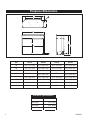
Fireplace Dimensions
F
C
E
A
B
D
G
H
Voltage: 120V AC, 60 Hz
Total Amps: 13.5 Amps
Total Watts: 1625 Watts
Heater Rating: 1300 Watts
Electrical Specifications
Ref. HEF22 HEF26 HEF33 HEF36
A
23¹⁄₂” (597 mm) 27¹⁄₂” (699 mm) 34¹⁄₂” (876 mm) 37¹⁄₂” (953 mm)
B
20³⁄₄” (527 mm) 25¹⁄₄” (641 mm) 29³⁄₄” (743 mm) 33¹⁄₄” (845 mm)
C 22” (559 mm) 26” (660 mm) 33” (838 mm) 36” (914 mm)
D 20” (508 mm)
24¹⁄₂” (622 mm)
29” (737 mm)
32¹⁄₂” (826 mm)
E
11¹⁄₂” (292 mm) 11¹⁄₂” (292 mm) 11¹⁄₂” (292 mm) 11¹⁄₂” (292 mm)
F 22” (559 mm) 18” (457 mm)
25⁵⁄₃₂” (639 mm) 28¹⁄₅” (716 mm)
G
21¹⁄₄” (540 mm) 25¹⁄₄” (641 mm) 32¹⁄₄” (819 mm) 35¹⁄₄” (895 mm)
H 15” (381 mm)
19¹⁄₂” (495 mm) 22³⁄₄” (578 mm) 26¹⁄₄” (667 mm)

5
10006946
A 15 amp, 120 Volt, 60 Hz circuit with a properly
grounded outlet is required. Preferably, the fireplace
will be on a dedicated circuit as other appliances on
the same circuit may cause the circuit breaker to trip or
the fuse to blow when the heater is in operation. The
unit comes standard with a 6 ft. (1.8 m) long three wire
cord, exiting the right side of the fireplace. Plan the
installation to avoid the use of an extension cord. If an
extension cord must be used, it must be a minimum 14
ga, three wire with grounding type plug and connector
and rated not less than 2025 Watts. The extension
cord shall not be more than 20 ft. (6m) in length.
Electrical Connection
Electrical outlet wiring must comply with
local building codes and other applicable
regulations to reduce the risk of fire,
electrical shock and injury to persons.
Do not use this fireplace if any part of it
has been under water. Immediately call a
qualified service technician to inspect the
fireplace and replace any part of the elec-
trical system which has been under
water.
WARNING:This procedure must be conducted by a
qualified electrician, in accordance with National and
local codes. In the U.S.A., the installation must con-
form to the National Electrical Code, ANSI/NFPA No.
70. In Canada, the installation must conform to the
current CSA C22.1 Canadian Electrical Code.
WARNING: Make sure the power to the unit is off, and
the power cord is unplugged from the wall outlet
before proceeding with this conversion. Failure to do
so may result in property damage, personal injury or
loss of life.
This instruction is intended as a guide for replacing the
power cord supplied with Models HEF22/26/33/36
electric fireplace with direct (hard) wiring.
NOTE: When direct wiring this appliance, it must be
connected to a 15 Amp dedicated circuit breaker or
fuse in the electrical panel of the dwelling. The cable
between the circuit/fuse panel and the fireplace must
meet all local and national codes, and in no case shall
the wires be less than 14 gauge.
1. Make sure the power to the unit has been turned
off, the power cord is unplugged from the wall outlet
and the unit has cooled down if it has been operat-
ing.
2. Follow Steps 3 through 6 in “Replacing Light Bulbs”
section, Page 7, to gain access to control panel
behind the touchpad controls.
3. Locate where the power cord enters the control
compartment on the right hand side of the unit.
Using wire cutters, cut the power cord within three
Direct (Hard) Wiring Electric Fireplace
inches (75mm) of the point where it exits the cabi-
net.
4. Carefully separate the three (3) wires of the power
cord into separate wires by gently pulling them
apart. DO NOT use a knife, as this may expose
bare conductor. The hot wire is connected on the
right hand side and is terminated with a 90° termi-
nal (marked as “power” on the control board). The
neutral wire is connected on the left hand side and
is terminated with a straight terminal marked as
“Neutral” on the control board. The green ground
wire is attached to a ground stud.
5. Using wire strippers, strip approximately 5/8"
(15mm) from the ends of the hot and neutral wires.
6. Using a wrench, remove the #10-24 hex nut from
the ground stud where the green wire from the
power cord is attached. Remove and discard the
green wire. Reinstall the nut but do not tighten yet.
7. While standing on the right side of the unit, locate
the power cord where it exits the cabinet. Using pli-
ers, gently cut and remove the power cord. Dispose
of the power cord.
8. Using a slotted screwdriver, remove the 7/8"
(22mm) diameter knockout from the right hand side
of the cabinet above where the strain relief was
located.
9. Route the electrical cable from the breaker/fuse
panel through the 7/8" (22mm) diameter hole and
secure to the cabinet using an approved clamp. The
power wires should extend approximately 6"
(152mm) into the control compartment.
WARNING: Make sure the power to the power cable
has been turned off at the breaker/fuse panel of the
residence before proceeding.
10. Connect the ground wire from the power cable by
wrapping it around the ground stud of the unit and
securing it using the #10-24 nut.
11. Using a wire nut, connect the hot lead (black), of
the power cable to the power cord wire that ends in
90° terminal (on the control board side, it ends on
your right hand side). Similarly, connect the neutral
wire (white), of the power cable to the power cord
ending with the straight terminal (on the control
board side, it ends on your left hand side) using a
wire nut. It is recommended that the wire nuts be
taped to the wires, using electrical tape, as an extra
safety measure.
12.Visually check that none of the wires in the control
compartment have been dislodged from the con-
trols. If they have, use the wiring diagram on the
unit or in the instruction manual to replace them in
their proper location.
13. Turn the power to the unit on at the breaker/fuse
panel. Place the unit into operation and check to
make sure that all of the systems are working prop-
erly.

6
10006946
WARNING: Disconnect power before
attempting any maintenance or cleaning
to reduce the risk of fire, electrical shock
or personal injury.
Service Instructions
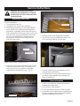
Replacing Front Cover
Access to heater/fan
1. Turn off power to the unit.
2. Let fireplace cool if it has been operating.
3. Remove fixed front panel, or open doors (depend-
ing on model). If the model has operable glass or
mesh doors, completely remove them from the unit
before proceeding. To remove the doors, locate and
remove the two (2) screws holding the door at the
top. (Fig. 1) Hold the door at all times with one
hand to prevent the door from falling when you
undo the hinge screws.
4. Locate the screws that hold the front cover in place.
There are six (6) screws, three (3) located on the
front of the unit (Fig. 2), and three (3) located
underneath the top shelf of the unit. (Fig. 3)
Fig. 1 Remove screws holding door at top.
Remove Screws
Fig. 2 Remove three (3) screws on front of unit.
Remove Screws
Remove Screws
Fig. 3 Remove three (3) screws located under top shelf.
5. Remove screws using appropriate screwdriver.
6. Pull out the front cover. holding both sides of the
cover, pull gently towards you and down.
Fig. 4 Hold both sides and pull gently forward and down.
7. You now have access to the heater/fan unit, for
cleaning and/or maintenance.
8. To reinstall the front cover, please follow reverse
procedure, paying attention not to damage any
wiring in the process.
Glass Information
1. Under no circumstances should this product be
operated with broken glass.
2. Do not strike or slam the glass.
3. Do not use abrasive cleaners to clean the glass.
4. This product uses tempered glass. Replacement of
the glass supplied by the manufacturer should be
done by a qualified service person.
Front Cover

Cleaning
Cleaning of the touchpad label at the bottom front of
the unit is to be done only using a soft cloth, slightly
dampened in water (if needed, a small amount of dish
soap can be added to the water) and dried using a
clean, dry soft cloth. DO NOT use any abrasive house-
hold cleaners as these products will damage the
touchpad controls.
7
10006946
Depending on your model, the fireplace uses two (2) or
three (3) clear 120 Volt, 60 Watt, E-12 socket base
light bulbs (small base, chandelier candle type). The
lights are located under the ember bed of the unit. For
convenience, if one of the light bulbs burns out, it may
be easier to replace all of the light bulbs at the same
time.
Do not exceed 60 Watts per bulb. Use of
higher rated bulbs may result in a fire,
causing property damage, personal injury
or loss of life.
1. Turn off power to the unit.
2. Let fireplace cool if it has been operating.
3. Remove fixed front panel, or open doors (depend-
ing on model).
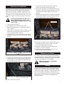
4. Locate two (2) screws that hold the refractory (brick
patterned) bracket together with the ember bed.
(Fig. 5) (Not applicable to HEF22)
5. Remove those two (2) screws using an appropriate
screwdriver. One screw is located on either side of
the unit.
Replacing the Light Bulbs
Remove Screws
Fig. 5 Remove screws that hold refractory bracket with
6. Pull the ember bed out of the unit, by gently pulling
towards you and only slightly upwards. Depending
on the model, you can remove the refractory prior
to removing the ember bed.
Pull Here (both sides)
Fig. 6 Pull ember bed out of unit.
7. Looking into the opening of the unit under the
ember bed, visually locate the light bulbs.
8. Remove the light bulbs by unscrewing them out of
the bases, turning them counterclockwise. You can
use one hand to hold the light socket in place, if
required.
9. Install the new light bulb(s) by turning the light bulb
into the base clockwise. You can use one hand to
hold the light socket in place, if required.
60 W Light Bulbs
Fig. 7 Remove and replace light bulb(s).
10.Reposition the ember bed. If required, gently raise
the refractory panels, one at a time, to tuck the
ember bed edge underneath them.
11.Reposition the refractory bracket, aligning the
refractory in place as required.
12.Replace two (2) screws taken out in Step 5, by
using an appropriate screwdriver.
Maintenance of Motors
The motors used on the fan and the drum assembly
are prelubricated for extended bearing life and require
no further lubrication. However, periodic cleaning/vacu-
uming of the fan/heater is recommended.
Make sure the power is turned OFF
before proceeding.

8
10006946
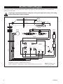
If repairing or replacing any electrical component or wiring, the original wire routing, color coding
and securing locations must be followed.
RETURN
LIGHT
HEATER
RETURN
3 RED
4 BLACK
1 RED
RED
BLACK
FLAME
MOTOR
MOTOR
+-
LIGHT
WHITE
BLACK
BLACK
BLUE
WHITE
BLACK
RED
LIMIT SWITCH
BLUE
FAN
MOTOR
LINE
NEUTRAL
NEUTRAL
2 WHITE
GREEN
GROUND
WARNING: Disconnect Power Before Servicing.
AVERTISSEMENT: Debrancher la source d’alimentation avant le service.
HEATER
CIRCUIT
BOARD
POWER
CORD
NO
COMM.
Electrical Wiring Diagram
Any electrical repairs or rewiring of this unit should be carried out by a licensed electrician in accordance with
national and local codes.
NOTE: HEF22/26 Units
have only 2 light bulbs

9
10006946
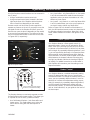
Operating Instructions
All of the fireplace control functions can be accessed in
two (2) ways:
• Using a multifunction remote control unit
• Using touchpad control panel, located in the lower
right-hand corner of the fireplace behind the door
front or fixed front (depending on the model).
Remote control unit has all the controls required to
operate any feature on the unit. If you prefer to use the
touchpad control on the fireplace unit itself, open the
fixed front or open the doors (depending on the model)
to access the touchpad buttons. The layout of the but-
tons on touchpad and remote control unit can be seen
in Figures 8 & 9, respectively.
R
6
5
4
A
3
2
1
Fig. 8 Touchpad buttons.
The fireplace features conveniently separate controls
for flame effect and for heater control. This allows you
to operate the unit in three (3) different modes:
• As a full-featured fireplace - both flame effect and
heater are on. This mode allows you to enjoy the
look of the fire along with the heat output of a
heater.
Flame Speed Control
Your fireplace features a flame speed control. By
depressing button 1 once you will activate the flame
effect. If this is the first time you use this unit, the visu-
al indicator of the flame effect (A) will be lit up to about
half its height. By repeatedly depressing buttons 2 and
3, you can respectively decrease or increase the flame
effect speed to achieve desired flame effect. Refer to
visual indicator A to monitor relative speed of the flame
effect between the slowest (indicator A showing only
one light) and fastest (indicator A showing all lights lit
up) setting. For added convenience, control board in
your fireplace will remember your last setting on sub-
sequent activation.
Heater Control
Your fireplace features a variable temperature setting
control. By depressing button 4 once, you will have
activated the heater. To change the comfort level in the
room, you can repeatedly depress buttons 5 and 6 to
decrease or increase the temperature setting, respec-
tively (for example, by repeatedly depressing button 6,
you will increase the temperature setting and your
room will feel warmer). To achieve the desired effect,
refer to visual indicator B, as your guide on the level of
the heat output.
ON/OFF
TEMP
FIRE
FIRE
TEMP
3
1
4
2
5
6
Turns unit OFF and starts BOTH
functions at remembered setting.
Fig. 9 Remote control.
• As a visual effect - only flame effect is on, the heater
is off. We recommend this mode for warm weather
application, when you want the ambiance of a fire,
without any heat output.
• As a heater - only heater is on, while the flame effect
is off. this mode allows you to use your fireplace as
an electric heater, without any flame effect.
Refer to Figure 8 & 9 for locations of the buttons on
both, the touchpad and remote control unit, described in
the following operating instructions. Note that in both
cases, button numbers as shown in the figures are the
same.

10
10006946
305mm [12"]
216mm [8 1/2"] (DISTANCE BETWEEN TWO SOCKETS}
216mm [8 1/2"] (DISTANCE BETWEEN TWO SOCKETS)
1
2
3
4
5
6
7
8
9
8
11
12
13
14
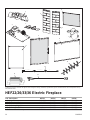
CFM Home Products reserves the right to make changes in design, materials, specifications, prices and discontinue colors and products at any
time, without notice.
HEF22/26/33/36 Electric Fireplace
Ref. Description HEF22 HEF26 HEF33 HEF36
1. Logset 10006656 10006711 10006532 10006587
2. Ember Lava Rock 10006655 10006710 10006526 10006588
3. Circuit Board 10006506 10006506 10006506 10006506
4. Refractory Right Side n/a 10006601 10006523 10006585
5. Refractory Left Side n/a 10006602 10006524 10006584
6. Screen Door Assembly 10006484 10006548 10006448 10006755

11
10006946
HEF22/26/33/36 Electric Fireplace (continued)
Ref. Description HEF22 HEF26 HEF33 HEF36
7. DC Motor 10001978 10001978 10001978 10001978
8. Glass Operable Door Assembly n/a 10006750 10006751 n/a
9. Folding Door n/a n/a 10006600 n/a
10. Glass Door Assembly n/a 10006551 10006543 n/a
11.Heater/Fan Assembly 10006538 10006538 10006538 10006538
12. Socket w/Wire Assembly 10006453 10006453 10006454 10006454
13. Power Cord 10003095 10003095 10003095 10003095
14. Flame Generator Assembly 10003566 10003566 10003350 10003350
15. Screen Diffuser (not shown) 10006480 10006423 10006422 10006576

1 YEAR WARRANTY
BASIC WARRANTY:
CFM Home Products (hereinafter referred to collectively as
the "Company") warrants that your new electric fireplace
is free from manufacturing and material defects for a peri-
od of one year from date of installation, subject to the fol-
lowing conditions and limitations.
1. This electric fireplace must be installed and operated at all
times in accordance with the Installation and Operating
instructions furnished with the product. Any alteration, willful
abuse, accident, or misuse of the product shall nullify this
warranty.
2. This warranty is non-transferrable, and is made to the origi-
nal owner, provided that the purchase was made through
an authorized supplier of the Company.
3. This warranty is limited to the repair or replacement of
part(s) found to be defective in material or workmanship,
provided that such part(s) have been subjected to normal
conditions of use and service, after said defect is confirmed
by the Company's inspection.
4. This warranty does not cover the lightbulb(s) included
with the fireplace.
5. The Company may, at its discretion, fully discharge all obli-
gations with respect to this warranty by refunding the
wholesale price of the defective part(s).
6. Any installation, labour, construction, transportation, or
other related costs/expenses arising from defective part(s),
repair, replacement, or otherwise of same, will not be cov-
ered by this warranty, nor shall the Company assume
responsibility for same. Further, the Company will not be
responsible for any incidental, indirect, or consequential
damages, except as provided by law.
7. All other warranties - expressed or implied - with respect to
the product, its components and accessories, or any obliga-
tions/liabilities on the part of the Company are hereby
expressly excluded.
8. The Company neither assumes, nor authorizes any third
party to assume, on its behalf, any other liabilities with
respect to the sale of this Norther Flame product.
9. The warranties as outlined within this document do not
apply to non-CFM Home Products accessories used in con-
junction with the installation of this product.
This warranty is void if:
a) The fireplace has been operated in atmospheres conta
minated by chlorine, fluorine or other damaging chemi-
cals.
b) The fireplace is subjected to prolonged periods of damp
ness or condensation.
c) Any alteration, willful abuse, accident, or misuse of the
product.
IF WARRANTY SERVICE IS NEEDED . . .
1) Contact your supplier. Make sure you have your warranty,
your sales receipt, and the model/serial number of your
CFM Home Products product.
2) DO NOT ATTEMPT TO DO ANY SERVICE WORK YOUR-
SELF.
GARANTIE DE BASE:
CFM Home Products (aux présentes nommée la "Société")
garantit votre nouveau cheminée électrique contre tous
défauts de fabrication et de matières premières pour une
période d'un an à compter de la date d'installation, sujet
aux conditions et limitations suivantes.
1. Le cheminée electrique doit être installé par un entrepre-
neur de service autorisé et compétent. Il doit être installé et
utilisé en tout temps selon les instructions d'installation et
de fonctionnement fournies avec le produit. Toute altéra-
tion, abus volontaire, accident ou mauvais usage du produit
annulera cette garantie.
2. Cette garantie n'est pas transférable et est offerte à l'a-
cheteur au détail d'origine, à condition que l'achat soit effec-
tué par l'entremise d'un détaillant autorisé de la Société.
3. Cette garantie est limitée à la réparation ou au remplace-
ment de(des) pièce(s) trouvée(s) défectueuse(s) en
matières premières ou main-d'oeuvre, à condition que les-
dites pièces aient été sujettes aux conditions normales
d'usage et de service, après que ledit défaut a été confirmé
par une inspection par la Société.
4. Cette Garantie ne couvre pas les ampoules inclus dans le
poêle électrique.
5. La Société peut, à sa discrétion, se décharger entièrement
de toutes obligations se rapportant à cette garantie en rem-
boursant le prix de gros de la(des) pièce(s) défectueuse(s).
6. Tous les frais/dépenses d'installation, de main-d'oeuvre, de
construction, de transport ou autres causés par une (des)
pièce(s) défectueuse(s), une réparation, un remplacement
ou autre, ne seront pas couverts sous cette garantie, et la
Société n'assume aucune responsabilité pour ceux-ci. De
plus, la Société ne pourra être tenue responsable pour tous
dommages fortuits ou indirects sauf la ou prévu par la loi.
7. Toutes autres garanties, exprimées ou sous-entendues, en
ce qui a trait au produit, ses composants et accessiores, ou
toutes obligations/responsabilités de la part de la Société
sont aux présentes expressment excluses.
8. La Société n'assume et n'autorise personne à assumer, en
son nom, toutes responsabilités en ce qui a trait à la vente
de ce produit Majestic Fireplaces.
9. Les garanties, telles que décrites dans ce document, ne
s'appliquent accessoires non CFM Home Products utilisés
conjointement pour l'installation de ce produit.
Cette garantie est nulle si:
a) Le cheminée a été utilisé dans une atmosphère contam-
inée par du chlore, du fluor ou tous autres produits chim-
iques.
b) Le cheminée est assujetti à de longues périodes d'hu-
midité ou de condensation.
c) Toute altération, abus volontaire, accident ou mauvais
usage du produit annulera cette garantie.
SI UN SERVICE SOUS GARANTIE EST REQUIS . . .
1) Communiquez avec votre détaillant. Assurez-vous que
vous avez votre garantie, votre reçu de caisse ainsi que le
numéro de modèle/série de votre produit CFM Home
Products.
2) NE TENTEZ PAS D'EFFECTUER DES REPARATIONS
VOUS-MEME.
CFM Corporation
2695 Meadowvale Blvd
Mississauga, Ontario
L5N 8A3 Canada
(800) 668-5323
www.cfmcorp.com
-
 1
1
-
 2
2
-
 3
3
-
 4
4
-
 5
5
-
 6
6
-
 7
7
-
 8
8
-
 9
9
-
 10
10
-
 11
11
-
 12
12


CFM HEF22 Manuel utilisateur
- Catégorie
- Cheminées
- Taper
- Manuel utilisateur
dans d''autres langues
- English: CFM HEF22 User manual
Autres documents
-
 pyromaster HEF33 Homeowner's Installation & Operating Manual
-
Pleasant Hearth GCE-1803 Homeowner's Installation And Operating Instructions Manual
-
Muskoka 240-158-354 Manuel utilisateur
-
Desa O36NR Le manuel du propriétaire
-
-
-
-
Classic Flame 80649 Manuel utilisateur
-
Superior Fireplaces DRI2000 Mode d'emploi
-
