
Content
QDSP-208C/D
Digital Signage Player with Intel® Haswell Processor
User’s Guide

Content
Content
Content ....................................................................................................................... 2
Figures ....................................................................................................................... 3
Tables ......................................................................................................................... 4
Safety Instructions ...................................................................................................... 5
Before You Begin ......................................................................................... 5
When Working Inside a Computer ............................................................... 6
Preventing Electrostatic Discharge .............................................................. 6
Instructions for Lithium Battery .................................................................... 7
Preface ....................................................................................................................... 8
How to Use This Guide ................................................................................ 8
Unpacking ................................................................................................... 8
Regulatory Compliance Statements ............................................................ 8
Maintaining Your Computer ....................................................................... 10
Chapter 1 Introduction ........................................................................................... 12
Overview ................................................................................................... 12
Product Specifications ............................................................................... 13
System tour ............................................................................................... 15
Mechanical Dimensions ............................................................................. 18
Chapter 2 Getting Started ...................................................................................... 19
Setting up your PC .................................................................................... 19
Connecting VESA Mount on QDSP-208C/D/D .......................................... 22
Mounting your PC to a monitor .................................................................. 23
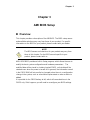
Chapter 3 AMI BIOS Setup .................................................................................... 24
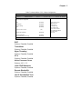
Overview ................................................................................................... 24
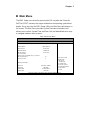
Main Menu ................................................................................................. 25
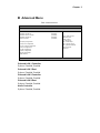
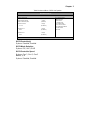
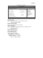
Advanced Menu......................................................................................... 26
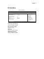
Boot Menu ................................................................................................. 34
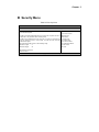
Security Menu ........................................................................................... 35
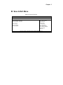
Save & Exit Menu ...................................................................................... 36
Chapter 4 Driver Installation .................................................................................. 38

Figures
Figures
Figure 1 Front IO ........................................................................................ 15
Figure 2 Rear IO ........................................................................................ 17
Figure 3 Mechanical Dimensions ............................................................... 18
Figure 4 Connect the VGA / DP / HDMI cable ............................................ 19
Figure 5 Connecting USB mouse & keyboard............................................ 20
Figure 6 COM port ..................................................................................... 20
Figure 7 Network cable with RJ45 connector ............................................. 21
Figure 8 Turning on the system ................................................................. 21
Figure 9 VESA Mount Assembly ................................................................ 22
Figure 10 VESA Mount on QDSP-208C/D ................................................. 22
Figure 11 VESA mounting .......................................................................... 23

Tables
Tables
Table 1 QDSP-208C/D/D Specification ......................... 14
Table 2 BIOS Main Menu .................................. 25
Table 3 Advanced Menu ................................... 26
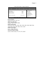
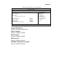
Table 4 Advanced Menu – Display Configuration ................. 27
Table 5 Advanced Menu – Super IO Configuration ................ 28
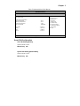
Table 6 Advanced Menu –Super IO Configuration – Serial Port 1
Configuration ..................................... 28
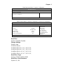
Table 7 Advanced Menu –CPU Chipset Configuration .............. 29
Table 8 Advanced Menu –SATA Configuration ................... 30
Table 9 Advanced Menu –USB Configuration .................... 31
Table 10 Advanced Menu –H/W Monitor ....................... 32
Table 11 Power Configuration ............................... 33
Table 12 Boot Menu ...................................... 34
Table 13 Security Menu ................................... 35
Table 14 Save & Exit Menu ................................. 36

Safety Instructions
Safety Instructions
n Before You Begin
Before handling the product, read the instructions and safety guidelines on the
following pages to prevent damage to the product and to ensure your own personal
safety. Refer to the “Advisories” section in the Preface for advisory conventions used
in this user’s guide, including the distinction between Warnings, Cautions, Important
Notes, and Notes.
n Always use caution when handling/operating a computer. Only qualified,
experienced, authorized electronics service personnel should access the
interior of a computer. The power supplies produce high voltages and
energy hazards, which can cause bodily harm.
n Use extreme caution when installing or removing components. Refer to the
installation instructions in this user’s guide for precautions and procedures.
If you have any questions, please contact our Post-Sales Technical
Support.
n Access can only be gained by service persons or by users who have been
instructed about the reasons for the restrictions applied to the location and
about any precautions that shall be taken; and access is through the use of
a tool or lock and key, or other means of security, and is controlled by
authority responsible for the location.
WARNING
High voltages are present inside the chassis when the unit’s power cord is
plugged into an electrical outlet. Turn off system power, turn off the power
supply, and then disconnect the power cord from its source before
removing the chassis cover. Turning off the system power switch does not
remove power to components.

Safety Instructions
n When Working Inside a Computer
Before taking covers off a computer, perform the following steps:
1. Turn off the computer and any peripherals.
2. Disconnect the computer and peripherals from their power sources or
subsystems to prevent electric shock or system board damage. This does not
apply when hot swapping parts.
3. Follow the guidelines provided in “Preventing Electrostatic Discharge” on the
following page.
4. Disconnect any telephone or telecommunications lines from the computer.
In addition, take note of these safety guidelines when appropriate:
n To help avoid possible damage to system boards, wait five seconds after
turning off the computer before removing a component, removing a system
board, or disconnecting a peripheral device from the computer.
n When you disconnect a cable, pull on its connector or on its strain-relief loop,
not on the cable itself. Some cables have a connector with locking tabs. If you
are disconnecting this type of cable, press in on the locking tabs before
disconnecting the cable. As you pull connectors apart, keep them evenly
aligned to avoid bending any connector pins. Also, before connecting a cable,
make sure both connectors are correctly oriented and aligned.
CAUTION
Do not attempt to service the system yourself except as explained in this
user’s guide. Follow installation and troubleshooting instructions closely.
n Preventing Electrostatic Discharge
Static electricity can harm system boards. Perform service at an ESD workstation
and follow proper ESD procedure to reduce the risk of damage to components. We
strongly encourages you to follow proper ESD procedure, which can include wrist
straps and smocks, when servicing equipment.
You can also take the following steps to prevent damage from electrostatic
discharge (ESD):

Safety Instructions
n When unpacking a static-sensitive component from its shipping carton, do not
remove the component’s antistatic packing material until you are ready to install
the component in a computer. Just before unwrapping the antistatic packaging,
be sure you are at an ESD workstation or grounded. This will discharge any
static electricity that may have built up in your body.
n When transporting a sensitive component, first place it in an antistatic container
or packaging.
n Handle all sensitive components at an ESD workstation. If possible, use
antistatic floor pads and workbench pads.
n Handle components and boards with care. Don’t touch the components or
contacts on a board. Hold a board by its edges or by its metal mounting bracket.
n Do not handle or store system boards near strong electrostatic, electromagnetic,
magnetic, or radioactive fields.
n Instructions for Lithium Battery
WARNING
Danger of explosion when battery is replaced with incorrect type. Only replace
with the same or equivalent type recommended by the manufacturer.
Do not dispose of lithium batteries in domestic waste. Dispose of the battery
according to the local regulations dealing with the disposal of these special
materials (e.g. to the collecting points for disposal of batteries)

Preface
Preface
n How to Use This Guide
This guide is designed to be used as step-by-step instructions for installation, and as
a reference for operation, troubleshooting, and upgrades.
n Unpacking
When unpacking, follow these steps:
1. After opening the box, save it and the packing material for possible future
shipment.
2. Remove all items from the box. If any items listed on the purchase order
are missing, notify our customer service immediately.
3. Inspect the product for damage. If there is damage, notify our customer
service immediately. Refer to “Warranty Policy” for the return procedure.
n Regulatory Compliance Statements
This section provides the FCC compliance statement for Class A devices.
FCC Compliance Statement:
This equipment has been tested and found to comply with limits for a Class A digital
device, pursuant to Part 15 of the FCC rules. These limits are designed to provide
reason able protection against harmful interference in residential installations. This
equipment generates, uses, and can radiate radiofrequency energy, and if not
installed and used in accordance with the instructions, may cause harmful
interference to radio communications. However, there is no guarantee that
interference will not occur in a particular installation. If this equipment does cause
interference to radio or television equipment reception, which can be determined by
turning the equipment off and on, the user is encouraged to try to correct the
interference by one or more of the following measures:
n Reorient or relocate the receiving antenna.
n Increase the separation between the equipment and receiver.
n Connect the equipment to an outlet on a circuit different from that to which the

Preface
receiver is connected.
n Consult the dealer or an experienced radio/TV technician for help.
Changes or modifications not expressly approved by your dealer could void the
user's authority to operate the equipment.
NOTE
The assembler of a personal computer system may be required to test
the system and/or make necessary modifications if a system is found to
cause harmful interference or to be noncompliant with the appropriate
standards for its intended use.

Preface
n Maintaining Your Computer
Environmental Factors
n Temperature
The ambient temperature within an enclosure may be greater than room
ambient temperature. Installation in an enclosure should be such that the
amount of air flow required for safe operation is not compromised.
Consideration should be given to the maximum rated ambient temperature.
Overheating can cause a variety of problems, including premature aging and
failure of chips or mechanical failure of devices.
If the system has been exposed to abnormally cold temperatures, allow a
two-hour warm-up period to bring it up to normal operating temperature before
turning it on. Failure to do so may cause damage to internal components,
particularly the hard disk drive.
n Humidity
High-humidity can cause moisture to enter and accumulate in the system. This
moisture can cause corrosion of internal components and degrade such
properties as electrical resistance and thermal conductivity. Extreme moisture
buildup inside the system can result in electrical shorts, which can cause
serious damage to the system.
Buildings in which climate is controlled usually maintain an acceptable level of
humidity for system equipment. However, if a system is located in an unusually
humid location, a dehumidifier can be used to maintain the humidity within an
acceptable range. Refer to the “Specifications” section of this user’s guide for
the operating and storage humidity specifications.
n Altitude
Operating a system at a high altitude (low pressure) can cause electrical
problems related to arcing and corona effects. This condition can also cause
sealed components with internal pressure, such as electrolytic capacitors, to fail
or perform at reduced efficiency.

Preface
Power Protection
脈䩃e greatest threats to a system’s supply of power are power loss, power spikes,
and power surges caused by electrical storms, which interrupt system operation
and/or damage system components. To protect your system, always properly
ground power cables and one of the following devices.
n Surge Protector
Surge protectors are available in a variety of types and usually provide a level
of protection proportional with the cost of the device. Surge protectors prevent
voltage spikes from entering a system through the AC power cord. Surge
protectors, however, do not offer protection against brownouts, which occur
when the voltage drops more than 20 percent below the normal AC line voltage
level.
n Line Conditioner
Line conditioners go beyond the over voltage protection of surge protectors.
Line conditioners keep a system’s AC power source voltage at a fairly constant
level and, therefore, can handle brownouts. Because of this added protection,
line conditioners cost more than surge protectors. However, line conditioners
cannot protect against a complete loss of power.
n Uninterruptible Power Supply
Uninterruptible power supply (UPS) systems offer the most complete protection
against variations on power because they use battery power to keep the server
running when AC power is lost. The battery is charged by the AC power while it
is available, so when AC power is lost, the battery can provide power to the
system for a limited amount of time, depending on the UPS system.
UPS systems range in price from a few hundred dollars to several thousand
dollars, with the more expensive unit s allowing you to run larger systems for a
longer period of time when AC power is lost. UPS systems that provide only 5
minutes of battery power let you conduct an orderly shutdown of the system,
but are not intended to provide continued operation. Surge protectors should be
used with all UPS systems, and the UPS system should be Underwriters
Laboratories (UL) safety approved.

Chapter 1
Chapter 1
Introduction
n Overview
The QDSP-208C/D is a compact size Box PC ideal for space critical applications.
This embedded hardware platform features 4th Generation Intel® Core™ i3/i5/i7
Processors, Intel® HM87 Express chipset, and DDR3L1333/1600 MT/S SO-DIMM. It
comes with a 2.5” SATA hard drive or SSD, 2x DP, 1x HDMI, 2x RJ-45, VGA, 6x USB
3.0, COM, and HD Audio.
The QDSP-208C/D provides high reliability for harsh environments, compact size,
high performance and is highly suited to a wide range of industrial applications such
as Digital Signage, Gaming, Transportation, Surveillance, and Thin Servers.
Checklist
n QDSP-208C/D
n Power Adapter
n Power Cord
n Driver CD
n Quick installation Guide
n VESA Mounting Kit
n Optional WiFi or 3G
Features
n Intel
®
Haswell Processor with QM87/HM87 Express chipset
n 2 x DDR3L 1333/1600 MT/S SO-DIMM up to 16 GB
n 1x VGA, 2x DP, 1x HDMI, 2x GbE and 5.1 channel audio output
n SATA HDD or SSD, 6x USB 3.0
n Support 4K x 2K Resolution
n Optional Wireless Ethernet or 3G Module

Chapter 1
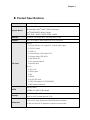
n Product Specifications
Construction Metal Housing
System Board
Intel
®
Haswell Processor
4th Generation Intel
®
Core™ i3/i5/i7 Processors
Intel
®
QM87/HM87 Express Chipset
(QDSP-208C:QM87) / (QDSP-208D:HM87)
Memory 2x DDR3L 1333/ 1600 MT/S SO-DIMM up to 16 GB
Graphic
Intel
®
HD Graphics 4600 supports 4K x 2K Resolution
I/O Panel
Front I/O
3x 3.5mm Phone Jack, support 5.1 channel audio output
1x S/PDIF Output
6x USB 3.0
1x Power Button ( With Power LED )
1x Storage status LED (HDD)
1x Wifi status LED
1x 3G external antenna
1x Reset Switch
Rear I/O
1x DC JACK
1x VGA output
2x DP
1x HDMI
2x RJ-45 GbE ports
1x COM Port support RS-232/422/485
2x Wifi external antennas
BIOS
AMI uEFI BIOS
1x128Mb SPI flash ROM onboard
Storage
2.5" SATA HDD or SSD
Up to 2x mSATA mixed with mini PCIe
Expansion
2 x mini PCIe slots (Optional for 3G/WiFi/Bluetooth module)
1x SIM card slot (for 3G appliance) support user accessible

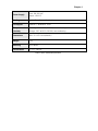
Chapter 1
Power Supply
Input: 100-240 VAC
Output: +19V DC
Cooling System Fan with smart fan function
OS Support Windows 7, Windows 8, Linux
Temperature /
Humidity
Operating: 0°C to 40°C, 0%-90%, non-condensing
Storage: -20°C to 80°C, 0%-90%, non-condensing
Dimensions 200 x 35 x 153.1 mm (WxHxD)
Weight 1 Kg
Mounting VESA Mount
Certifications CE, FCC Class A
Table 1 QDSP-208C/D/D Specification

Chapter 1
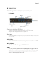
n System tour
Refer to the figures below to identify the components of the system.
n Front IO
Figure 1 Front IO
Power Button (with Power LED (Blue) )
The power push button allows powering ON and OFF the system.
The power LED will light when the PC is power-on.
Reset Switch
To clear the CMOS, use the tip of a pen to press the button briefly (for less than
three seconds).
HDD LED (Red)
The hard disk LED blinks when data is being written into or read from the HDD.
WiFi LED (Green)
When the data is Transferring, the WiFi LED will blink.
USB 3.0
The USB (Universal Serial Bus) port is compatible with USB devices such as
keyboards, mouse devices, cameras, and hard disk drives. USB allows many
devices to run simultaneously on a single computer, with some peripheral
acting as additional plug-in sites or hubs.

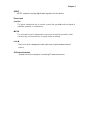
Chapter 1
S/PDIF
S/PDIF output for carrying digital audio signals out to the device.
Phone Jack
Line Out
The stereo headphone jack is used to connect the system’s audio out signal to
amplified speakers or headphones.
MIC-IN
The microphone jack is designed to connect the microphone used for video
conferencing, voice narrations, or simple audio recordings.
Line-IN
The Line-in jack is designed to take input from a higher-powered sound
source.
3G External Antenna
Spared hole on the casing for connecting 3G external antenna

Chapter 1
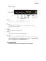
n Rear Rear
Figure 2 Rear IO
COM
D-Sub 9 pin connector for RS-232/422/485 connection
Ethernet
The eight-pin RJ-45 LAN port supports a standard Ethernet cable for
connection to a local network.
HDMI
HDMI connector for display output
VGA
D-Sub 15 pin VGA connector for display output
DC Jack
The supplied power adapter converts AC power to DC for use with this jack.
Power supplied through this jack supplies power to the PC. To prevent damage
to the PC, always use the supplied power adapter.
WiFi External Antenna
Spared hole on the casing for connecting WiFi external antenna

Chapter 1
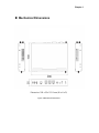
n Mechanical Dimensions
Dimension: 200 x 35 x 153.1 mm (W x H x D)
Figure 3 Mechanical Dimensions

Chapter 2
Chapter 2
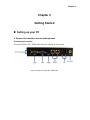
Getting Started
n Setting up your PC
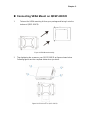
■ Connect the monitor, mouse and keyboard
Connecting the monitor
Connect the VGA / DP / HDMI cable from your display to the system.
Figure 4 Connect the VGA / DP / HDMI cable

Chapter 2
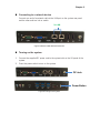
Connecting USB mouse & keyboard
Your QDSP-208C/D does not come with a keyboard and mouse, but you can use any
USB keyboard or mouse with your computer.
Figure 5 Connecting USB mouse & keyboard
NOTE
Using a third-party USB mouse or keyboard may require software drivers.
Check the manufacturer’s website for the latest software drivers.
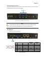
n COM port
COM port with the pin definitions.
Pin
RS-232 RS-422
Half Duplex
RS-485
Full Duplex
RS-485
1 DCD TX- DATA- TX-
2 RXD RX+ NA RX+
3 TXD TX+ DATA+ TX+
4 DTR RX- NA RX-
5 GND GND GND GND
6 DSR NA NA NA
7 RTS NA NA NA
8 CTS NA NA NA
9 RI / +5V* NA / +5V* NA / +5V* NA / +5V*
Figure 6 COM port
6xUSB 3.0
COM
La page est en cours de chargement...
La page est en cours de chargement...
La page est en cours de chargement...
La page est en cours de chargement...
La page est en cours de chargement...
La page est en cours de chargement...
La page est en cours de chargement...
La page est en cours de chargement...
La page est en cours de chargement...
La page est en cours de chargement...
La page est en cours de chargement...
La page est en cours de chargement...
La page est en cours de chargement...
La page est en cours de chargement...
La page est en cours de chargement...
La page est en cours de chargement...
La page est en cours de chargement...
La page est en cours de chargement...
-
 1
1
-
 2
2
-
 3
3
-
 4
4
-
 5
5
-
 6
6
-
 7
7
-
 8
8
-
 9
9
-
 10
10
-
 11
11
-
 12
12
-
 13
13
-
 14
14
-
 15
15
-
 16
16
-
 17
17
-
 18
18
-
 19
19
-
 20
20
-
 21
21
-
 22
22
-
 23
23
-
 24
24
-
 25
25
-
 26
26
-
 27
27
-
 28
28
-
 29
29
-
 30
30
-
 31
31
-
 32
32
-
 33
33
-
 34
34
-
 35
35
-
 36
36
-
 37
37
-
 38
38


Quanmax QDSP-3000 Series Manuel utilisateur
- Taper
- Manuel utilisateur
dans d''autres langues
- English: Quanmax QDSP-3000 Series User manual
Autres documents
-
Aplex APC-3595R Manuel utilisateur
-
Contec BX-825 Le manuel du propriétaire
-
-
-
 Winmate W22IK3S-SPA3 Manuel utilisateur
-
ViewSonic VS13172 Manuel utilisateur
-
 Winmate IW32 3.5 SBC Manuel utilisateur
-
Rev-A-Shelf CW35-AC Manuel utilisateur
-
 Winmate R17IH3S-MLA1-89 Manuel utilisateur
-
Lanner NCA-4240 Manuel utilisateur


